7955 Cameron Brown Court - Ready Remote
7955 Cameron Brown Court - Ready Remote
7955 Cameron Brown Court - Ready Remote

You also want an ePaper? Increase the reach of your titles
YUMPU automatically turns print PDFs into web optimized ePapers that Google loves.
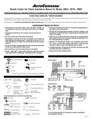
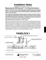
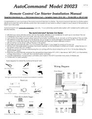
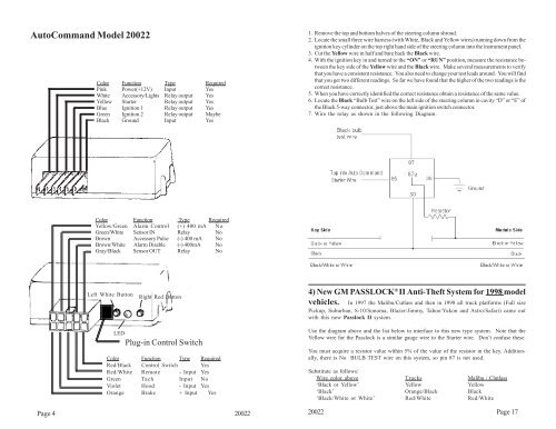
AutoCommand Model 20022Color Function Type RequiredPink Power(+12V) Input YesWhite Accessory/Lights Relay output YesYellow Starter Relay output YesBlue Ignition 1 Relay output YesGreen Ignition 2 Relay output MaybeBlack Ground Input Yes1. Remove the top and bottom halves of the steering column shroud.2. Locate the small three wire harness (with White, Black and Yellow wires) running down from theignition key cylinder on the top right hand side of the steering column into the instrument panel.3. Cut the Yellow wire in half and bare back the Black wire.4. With the ignition key in and turned to the “ON” or “RUN” position, measure the resistance betweenthe key side of the Yellow wire and the Black wire. Make several measurements to verifythat you have a consistent resistance. You also need to change your test leads around. You will findthat you get two different readings. So far we have found that the higher of the two readings is thecorrect resistance.5. When you have correctly identified the correct resistance obtain a resistance of the same value.6. Locate the Black “Bulb Test” wire on the left side of the steering column in cavity “D” or “E” ofthe Black 5-way connector, just above the main ignition switch connector.7. Wire the relay as shown in the following Diagram.Color Function Type RequiredYellow/Green Alarm Control (+) 400 mA NoGreen/White Sensor IN Relay No<strong>Brown</strong> Accessory Pulse (-) 400 mA No<strong>Brown</strong>/White Alarm Disable (-) 400mA NoGray/Black Sensor OUT Relay NoLeft White ButtonRight Red Button4) New GM PASSLOCK ® II Anti-Theft System for 1998 modelvehicles. In 1997 the Malibu/Cutlass and then in 1998 all truck platforms (Full sizePickup, Suburban, S-10/Sonoma, Blazer/Jimmy, Tahoe/Yukon and Astro/Safari) came outwith this new Passlock II system.LEDPlug-in Control SwitchColor Function Type RequiredRed/Black Control Switch YesRed/White <strong>Remote</strong> - Input YesGreen Tach Input NoViolet Hood - Input YesOrange Brake + Input YesPage 4 20022Use the diagram above and the list below to interface to this new type system. Note that theYellow wire for the Passlock is a similar gauge wire to the Starter wire. Don’t confuse these.You must acquire a resistor value within 5% of the value of the resistor in the key. Additionally,there is No BULB TEST wire on this system, so pin 87 is not used.Substitute as follows:Wire color above Trucks Malibu / Clutlass‘Black or Yellow’ Yellow Yellow‘Black’ Orange/Black Black‘Black/White or White’ Red/White Red/White20022 Page 17