7955 Cameron Brown Court - Ready Remote
7955 Cameron Brown Court - Ready Remote
7955 Cameron Brown Court - Ready Remote

You also want an ePaper? Increase the reach of your titles
YUMPU automatically turns print PDFs into web optimized ePapers that Google loves.
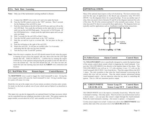
12A. Tach Rate LearningNote: Only use if the tachometer sensing method is chosen.A. Connect the GREEN wire to the car’s tach wire under the hood.B. Turn the On/Off control switch to the “OFF” position. Wait 5 secondsfor the flashing of the red LED to stop.C. Push the white button to the left of the red LED once and you will see thered LED flash. Now push the red button on the right side for a seconduntil you see the red LED flash again. You are now in TACH mode. (Ifthe LED flashed twice -- simply push the right button again until you getonly one flash).D. Wait 5 seconds for the red LED to flash 3 times.E. Turn the On/Off control switch back to the “ON” positionF. Start the car and let it get to a normal idle. Do not press on the gaspedal.G. Push the red button to the right of the red LED.H. Watch the red LED. It will turn on (solidly) after 3 or 4 seconds,indicating that the idle rate has been learned.I. Turn the key to the “Lock/Off” position.Note: Once this step is complete, the red LED should remain lit only when the engineis running (at up to twice the learned idle rate--above this rate the LED lightshould shut off). THIS IS CRITICAL. Confirm this by running the engine(with the key in the ignition) and pressing the gas pedal to raise the idle rate totwice the normal rate. The red LED should turn off. If it does not turn off,repeat the tach rate learning step and check the GREEN wire connection andlocation.13. Red/White Wire <strong>Remote</strong> Input Control HarnessThe RED/WHITE wire is used to trigger the AutoCommand® to start. Giving thiswire a negative pulse will cause the AutoCommand® to start. Giving it another negativepulse will cause it to stop.Hook this wire up to the output wire of your remote car alarm or keyless entry system.Or, hook it to the lock or unlock wire of your vehicle and set Option 8 as described inSection 21.This input wire can also be triggered by our optional Smart Car Pager accessory whichcan be controlled from any telephone anywhere in the world. This option requires thepager module, an activation fee of $25 and a monthly service fee of $3.00/mo.OPTIONAL STEPSMany of the optional steps require a relay to be hooked up. The most common relayused for this type of application is the Bosch type automotive relay P/N 0332209150. Use the diagrams below for a typical hookup. If you use another type ofrelay, then you need to know that pins 85 and 86 in this diagram represent the coilsof the relay. Pin 30 is the common and pin 87 is the normally open contact. If yourrelay has a pin 87A, then it is not used for these applications. The diagrams below aretypically used for applications such as headlamp or parking lamp connections.14.Yellow/Green Alarm ControlControl HarnThe YELLOW/GREEN wire is specifically designed to control the Ignition Inputof the remote control alarm system which is triggering the AutoCommand. Connectthis YELLOW/GREEN wire directly to the Ignition Input of the alarm. ThisYELLOW/GREEN wire will go to +12 volts anytime it sees +12 volts on theAutoCommand’s BLUE IGN 1 wire from the key. Thus this output follows the IGN1 status. The only exception is that when the AutoCommand is powering up thevehicle this wire will not activate. Thus the alarm remains operational duringAutoCommand control -- but not otherwise when the key alone is controlling theigntion. This is a 300 mA transistor positive output.15. GREEN/WHITE Sensor Loop IN Control HarnGRAY/BLACK Sensor Loop OUT Control HarnThis GREEN/WHITE wire is the input to a normally closed relay. When the Auto-Command is running -- this relay opens. Thus if you have an external sensor such asa shock sensor -- you can pass this sensor’s output through the AutoCommand.When the AutoCommand is running -- this sensor is opened -- or bypassed.Cut the sensor output wire in half. Connect one side to this GREEN/WHITE wireand the other side of the cut sensor wire to the GRAY/BLACK wire.Page 10 2002220022 Page 11