Induction Motors
Induction Motors
Induction Motors

Create successful ePaper yourself
Turn your PDF publications into a flip-book with our unique Google optimized e-Paper software.
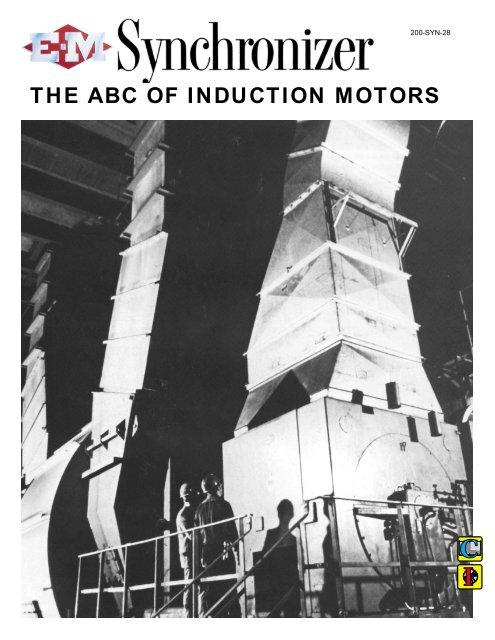
200-SYN-28THE ABC OF INDUCTION MOTORS
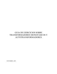
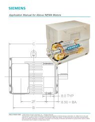
BIG MOTORSFOR BIG JOBS(Right) 3500 hp 1780 rpm, 4160 volt squirrel-cageinduction motor for driving waterpump. Ventilating air is recirculated in themotor through air cooler on top. Bearingsuse flood lubrication from gear driven oilpump in bearing pedestals. Main driveshaft extension is on opposite side.(Below) The “Straight-Up-Ventilated”induction motor for boiler feed pump driveand other large, high speed applications.The motor has split-level intake and discharge,and the discharge goes straightup. Eliminates cross-circulation, insuresbetter cooling and greater operator comfort.2
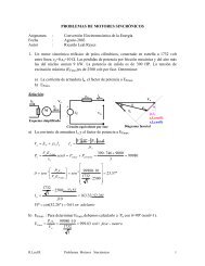
Two-Pole, 1500 HP <strong>Motors</strong> Driving Boiler Feed Pumps in MidwestUnderground Mine Pump with Drip-Proof Motor 350 HP, 1800 RPMThree 500 HP, 3560 RPM Oil Pipeline Pumps, Ventilated Through Base600 HP, 3560 RPM Sil-Clad Weather Protected <strong>Motors</strong> on Pipe LineKiln Fans at Cement Plant Driven by 250 HP, 1800 RPM <strong>Motors</strong>Draft Fan Driven by 1000 HP Outdoor Motor<strong>Induction</strong> <strong>Motors</strong>they provide reliablelow-maintenance drive power3
THEABCOF LARGEINDUCTION MOTORS<strong>Induction</strong> <strong>Motors</strong> are the “work-horses” of modernindustry. This is particularly true in the medium and highspeeds, because as shown in this article, the power factorand efficiency, above 500 rpm, are quite acceptable for mostapplications.The ruggedness and simplicity of squirrel-cage motorsmakes them a first choice where constant speed is acceptable.The every-day needs of industry find squirrel-cagemotors filling almost every conceivable constant-speed driverequirement.Where speed control or frequent reversing is desired, orwhere high controllable torque and extra-low starting currentmust be associated, wound-rotor (slip-ring) inductionmotors are used.Many designs and types of induction motors, some ofthem extremely special, are required to supply all needs ofindustry. The construction, operation, application and controlof the more common ones are discussed in this article.Mr. G. L. Oscarson, the author of this special issue of the E-M Synchronizer is therecipient of two Electrical Engineering degrees from the Institute of Technology,University of Minnesota. Specializing in electrical power apparatus, Mr Oscarsonwas for seventeen years directly associated in the field with the industrial applicationof motors, generators and controls. He has been Chief Application Engineer of theElectric Machinery Mfg. Company, since 1940, responsible for the coordination ofapplication requirements of large power apparatus. This paper is one of many Mr.Oscarson has prepared both for publication for presentation to engineering groups.Mr. Oscarson is a Fellow and Life Member of A.I.E.E., a member of the CementIndustry Committee of A.I.E.E., a member of the Electrical Engineering Committee ofTAPPI, a registered Professional Engineer.TABLE OF CONTENTS:Part 1 Fundamentals of AlternatingCurrent and <strong>Induction</strong> <strong>Motors</strong>Alternating-Current Formulas . . . . . . . . . .5Power Factor and Magnetizing Current . . .6Torque, Synchronous Speeds, Slip,Efficiency, Horsepower Determination . .7, 8, 9Insulation and Temperature Rise . . . . . . . .9Protective Constructions . . . . . . . . . . . . .10Mechanical Constructions . . . . . . . . . . . .11Part 2 How the <strong>Induction</strong> MotorOperates; Torque Characteristics;Construction FeaturesExplanation of Operation . . . . . . . . . . . . .12Torque . . . . . . . . . . . . . . . . . . . . . . . . . .13Rotor Construction . . . . . . . . . . . . . . 14, 15Construction Features . . . . . . . . . . . . 16, 17Part 3 Application and StartingMethods for <strong>Induction</strong> <strong>Motors</strong>Squirrel-Cage Motor Classifications . . . .18Starting Current of Squirrel Cage <strong>Motors</strong> .19Reduced Kva Starting . . . . . . . . . . . . . . .20Methods of Starting . . . . . . . . . . . . . . . .21Multi-Speed Squirrel-Cage <strong>Motors</strong> . . . . .22Wound-Rotor <strong>Induction</strong> <strong>Motors</strong> . . . . . . .23Speed and Starting Characteristicsof Wound-Rotor <strong>Motors</strong> . . . . . . . . . . .24, 25Part 4 <strong>Induction</strong> Motor Control;Adjustable-Speed Magnetic DriveSquirrel-Cage Motor Control . . . . . . . 26, 27Wound-Rotor Motor Control . . . . . . . 26, 28Adjustable-Speed Magnetic Drive . . . . . .284
PART ONEA BRIEF EXPLANATION of some alternating-current formulasand definitions; and a review of induction motor characteristics,insulations, and constructions.Alternating current (AC)A-C Voltage alternates regularly in value and in direction.A single-phase wave of a-c voltage is illustrated inFig. 1. One complete set of alterations, positive and negative,is one cycle or 360 electrical degrees.Inductance (L)—Any device with iron in the magneticcircuit has what amounts to magnetic inertia. This inertia iseffective on any change in current. Since the voltage, andtherefore the current, is always changing in value on alternatingcurrent, the inertia characteristic of opposing anychange in current causes the current change to lag behindthe voltage change. It also serves to limit the current value.This effect, known as inductance, is measured in henries.Inductive Resistance (X 1 )—The effect of inductancevaries with the frequency, and the term Inductive Reactanceis used to express this effect.Frequency (f) is the number of such alterations per second.Perfect alternating current is a sine wave with no ripplesor distortions.Phase—If the electrical power is supplied over two circuits,in one of which the voltage reaches zero and othercorresponding values 90 degrees later than in the other circuit,the service is Two Phase (Fig. 2). If the power is providedin what amounts to three circuits which reach correspondingvalues at 120 deg. intervals, the service is ThreePhase (Fig. 3).Impedance (Z)—On alternating-current circuits the flowof current is limited by both resistance and inductive reactance.The combination of these two elements is known asimpedance. Mathematically, when resistance and inductivereactance are present:Volts (E)—The Volt is the common measure of electricalpressure. Effective Voltage, also called RMS voltage (rootmean-squarevoltage), is .707 of the maximum value of thevoltage wave as shown in Fig. 1. Effective voltage is thevoltage measured by the usual a-c voltmeter.Amperes (I)—The Ampere is the unit rate of flow ofelectric current. As commonly used it is the effective(RMS) value of alternating current and is the value indicatedby a common a-c ammeter.Resistance (R)—Resistance is the measure of hindranceor impedance to current flow on direct current. Resistanceis measured in ohms. Fundamental Ohms law is:Actually in most a-c circuits the value of X 1 is so high comparedto the value of R that for a first approximation it isassumed:Power (W)— Electrical power is measured in watts (W),kilowatts (Kw+W/1000) or megawatts (Mw=W/1,000,000).A watt is the product of ampere effective current flowing ata pressure one effective volt. In alternating current a furthercondition is that the voltage and current must be in phase,that is they must both reach zero, maximum positive andmaximum negative values at the same instant.5
Assuming that the voltage and current are in phase,If the current and voltage are not in phase, that is, do notreach corresponding values at the same instant, the resultantproduct of current and voltage is apparent power instead ofactual power. Apparent power is measured in volts-amperes(Va) or kilovolt amperes (Kva = VA/1000).Apparent Power is measured as follows:that amount of lag, is 0.50 corresponding to 0.5 (or 50.0%)lagging power factor.Low power factor is undesirable. The capacity ofgenerators, transformers, transmission lines and distributionlines is usually fixed by heating limits or by permissiblevoltage drop. In any case the current is usually the limitingfactor. Since power factor = Kw/Kva any decrease in powerfactor means an increase in Kva (and therefore amperes) fora given Kw load.Approximate power factors of typical NEMA Class Bmotors are shown in the curves on the opposite page. Notethat decrease in rated speed or in rated horsepower results inlower power factor at all loads.Variation in line voltage will affect the power factor ofinduction motors. In general the following may be expected:Power Factor is the factor by which apparent power(volt-amperes) is multiplied to obtain actual power (watts).In most magnetic circuits as mentioned above, the currentwill lag behind the voltage. A typical case is represented inFig. 4, where the current changes lag 60 degrees (1/6 cycle)behind corresponding voltage changes. In that part of thecurrent wave and voltage wave when both are positiveor both negative, the resulting power is positive(E x I =W, or -E x -I = W). This is represented by the crosshatched area above the zero line.Thus if the full-load power factor of a motor at normal voltageis 0.896, a 10% increase in voltage will lower the powerfactor to 0.866.Magnetizing Current Transformers, motors and otherapparatus with magnetic circuits containing iron must bemagnetized in order to operate. It is often convenient tospeak of the input current as having two components: one aload component which is in phase with the voltage, and theother a magnetizing component at right angles and laggingthe voltage. This lag would be 90 electrical degrees.When either the current wave or voltage wave is negativeand the other is positive the resulting power is negative (-Ex I = -W, or E x -I = -W). This is represented by the crosshatched area below the zero line. The net power is the positivearea minus the negative area. The apparent power(volt-amperes) is the sum of the two areas. The power factoris the net power divided by apparent power.Thus power factor is the factor by which we multiply apparentpower to determine actual power.Mathematically, power factor is equal to the cosine of theangle by which the current lags (or in rare cases leads) thevoltage. In Fig. 4, the angle lag is 60 degrees. The cosineof this angle, and thus the corresponding power factor, forThe load component registers on the watthour meter anddoes the actual work. The magnetizing component putsenergy into the magnetic circuits of the apparatus during1/4 cycle and returns it to the system the next quarter cycle.This is illustrated in Fig. 5 where positive and negative areasrepresenting power are equal and cancel out. Except forlosses, the net power interchange due to the magnetizingcomponent is zero.6
Power Factor of <strong>Induction</strong> <strong>Motors</strong> (Approx.)Mathematically:alsoTorque (T) is the turning effort at one foot radiusexpressed in pound-feet. It is a measure of the ability of amotor to develop power. National Electrical ManufacturersAssociation has defined the torques applying to inductionmotors in NEMA “Motor and Generator Standards”.(NEMA -MG 50)Locked-Rotor Torque (also called breakaway torque orstarting torque) is the minimum torque a motor will developat rest for all angular positions of the rotor, with rated voltageapplied at rated frequency (NEMA-MG 50-67).Full-Load Torque is the torque necessary to producerated horsepower at full-load speed. In pounds at one footradius it is equal to the horsepower times 5250 divided bythe full-load speed (NEMA-MG 50-66.5).For example, a 500 hp, 1760 rpm motor will have the followingfull-load torque:Accelerating Torque is the net difference, at any speed,between the torque required by the external load and thetorque developed by the motor. This torque is available foracceleration of the motor and its connected load.Breakdown Torque is the maximum torque a motor willdevelop, with rated voltage applied at rated frequency, withoutan abrupt drop in speed (NEMA-MG 50-69). This issometimes incorrectly referred to as the maximum torque orpull-out torque.Starting and breakdown torques will vary as the square ofthe applied voltage. For instance, if a motor has 125% startingtorque on full voltage, and the voltage is reduced to 80%of normal, the resulting starting torque will be:In some cases the starting or accelerating torque availableat reduced voltage may be insufficient to start or bring theconnected load up to speed.Synchronous Speed is the speed an induction motorwould reach if there were no slip. It is the speed at whichthe magnetic field, in effect, rotates about the stator.7
Common induction motor synchronous speeds are:Full-Load Speed and Slip As explained later, theEfficiency of <strong>Induction</strong> <strong>Motors</strong> (Approx.)rotor of the induction motor can never run at quite synchronousspeed. The difference between synchronous speed andoperating speed is known as slip. This is usually expressedin percent of synchronous speed.For example, a 200 hp, 2-pole. 60 cycle motor may have afull-load speed of 3560 rpm. Synchronous speed would be3600 rpm.Full-load slip varies from 1% on large, high-speed inductionmotors to 3% on small, low-speed motors. For specificapplications higher slip values may be built into a motor.If the line voltage is 10% high, the slip will be reducedabout 1 point. If the line voltage is 10% low the slip will beincreased about 1.5 points.Efficiency is the measure of the ability of the motor toconvert electrical input to mechanical output.The kilowatt is the common unit of electrical input. Thehorsepower is the common unit of mechanical output.The recognized induction motor losses are:If a motor has an input of 94 kw and an output of 110 hp,efficiency will be as follows:The internal torque developed by the squirrel-cage inductionmotor is due to the losses generated in the rotor. In the caseof a wound-rotor induction motor, the losses in the externalresistor are also included.A 1200 rpm synchronous motor developing 96 hp at 1160rpm, would have rotor losses as follows:8
Slip loss may also be determined by the following formula:296 amperes at 440 volts, operating at 160 amperes and at445 volts. Apparently this will be close to half load so weassume efficiency and power factor values from the curves(assume 90.5 and 85.5 respectively) for that load. The voltageis close enough to rated value so no correction need bemade for that. Then:For the motor specified above:Curves on opposite page show approximate efficiencies ofNEMA Design B <strong>Motors</strong>.Variation in line voltage will affect the efficiency ofinduction motors. In general the following may be expected.which is sufficiently close to half load so that the assumedvalues of efficiency and power factor, as used, will suffice.If the calculated load is not close to the load value, onwhich assumed efficiency and power factor values werebased, it may be necessary to use new values correspondingto the estimated load and try again.If a wattmeter is available, one variable, viz; power factor, iseliminated. Then:Horsepower Determination—In some cases it willbe desirable to determine approximate horsepower loadingby measuring motor input with a voltmeter and ammeter orwith a wattmeter.Ammeter readings alone are not too accurate. However, ifline voltage is at the nameplate value and if the ammeterreading is between 3/4 of full-load amperes and 1 1/4 fullloadamperes, it may be assumed that the load is very nearlyproportional to the ammeter reading.A 250 hp motor has a nameplate full-load current rating of298 amperes at 440 volts and is drawing 260 amperes at thatvoltage. It can be assumed that the load is very nearly proportional:That is:If the voltage is appreciably high or low a correction may bemade on the following basis:At current values below 3/4 of rated amperes it will be necessaryto cut and try. First assume efficiency and power factorvalues, based on an estimate of the load, correcting forvoltage if necessary, and substituting in the following formula:Assume a 250 hp, 1800 rpm motor with nameplate rating ofIt is then necessary to assume an efficiency value, takinginto account horsepower, speed, approximate load and voltagevariation from normal.Assume that the 250 hp, 1800 rpm motor previously mentionedwas checked by wattmeter and had an input of 90 kw.For a first approximation assume an efficiency of 90%.Then:By referring to the efficiency curves we find that the valueat half load is 90.5% and the assumed value of 90% whichwas used is nearly enough accurate. If the efficiency at theload as determined above is not close to the assumed valueit will be necessary to make a correction. The efficiencyvalue at the load as determined should be used and thehorsepower recalculated. One such trial should make it possibleto arrive at a sufficiently close approximation of theactual horsepower.Insulation and Temperature RiseAmbient Conditions—It is assumed that the temperatureof the air surrounding a motor is not over 40 degrees C(104 degrees F) and that the altitude does not exceed 3300feet. The lower density of the cooling air at high altituderesults in reduced cooling. In general however, any increasein altitude results in a lowering of ambient temperature, offsettingthe decreased cooling effect. The total temperaturebased on lower ambient but a higher temperature rise, isusually about the same regardless of altitude.Total temperature is important in that it directly influenceslife of the insulation of the motor. It is generallyaccepted that each 10 degrees C rise in temperature willapproximately halve the effective life of Class A or Class Binsulation. Actual failure of the insulation is generallymechanical, resulting from reduced strength of the insulationdue to continual or repeated exposure to high temperature.9
105°C (Class A) Insulation is based on a total allowabletemperature on a material and processing systemapproved in AIEE #1 as being suitable for reasonable insulationlife. This is based on:Such units will require special tropical insulation.Protective ConstructionsClass A insulation usually consists of cotton, silk paper orother organic material impregnated with insulating varnish;molded or laminated phenolics; films or sheets of syntheticresins and enamels as applied to conductors.The 15 degree C hot spot allowance presupposes that thehottest spot is 15 degrees C hotter than the maximum temperatureobserved by external thermometer. The 10 degreesC service factor permits a 40 degrees C rise general purpose,dripproof induction motor to carry 15% overload continuouslywithout a temperature rise which would be undulydamaging to insulation.Class A insulation and 40 degree C rise has been consideredstandard but the current trend is toward single rated motors,Class A with 50 degree C rise or Class B with 70 degree Crise.Special Class A Insulation is processed to a greaterthan standard Class A and is used where Dyehouse,Packinghouse or Boiler House insulation is called for. It ishighly resistant, but not “proof” against severe conditions ofmoisture, dampness, conductive or abrasive dust, acid oralkali dusts or vapors.130°C (Class B) insulation is based on:Open type Motor—(NEMA-MG 50-40) is a self-ventilatedmotor having no restriction to ventilation other thanthat necessitated by mechanical construction.Drip-proof <strong>Motors</strong>—(NEMA-MG 50-14), have ventilatingopenings so constructed that drops of liquid or fallingparticles reaching the motor at an angle not greater than 15degrees from the vertical cannot enter the motor eitherdirectly or by striking and running along a horizontally orinwardly inclined surface. This is the recommended minimumprotection for the great majority of induction motorapplications.Splash-proof <strong>Motors</strong>—(NEMA-MG 50-16), Fig. 12,have ventilating openings so constructed that the drops ofliquid or solid particles falling on the motor or comingstraight toward it an angle not greater than 100 degrees fromthe vertical cannot enter the motor directly or by runningalong the surface.Splash-proof motors are frequently used in ice plants,dairies, creameries, paper mills, chemical plants, and otherplaces where floors may be hosed down. They are also suitablefor installation outdoors except where drifting snowClass B Insulation usually consists of mica, asbestos,fibre glass, other inorganic materials, and synthetic resinsand fibers as determined by test. Other materials may beused for binders and for structural purposes.155° C (Class F) Insulation consists of a systemincorporating materials and processes approved in AIEE #1as being suitable for operation at a total temperature of 155degrees C; as proven by established tests and usage.180°C (Class H) Insulation consists of recentlydeveloped materials, basically silicones, and insulating systemssuitable for operation at a total temperature of 180degrees C. However, full advantage of this allowable temperaturerise securing reduction of motor frame size is usuallynot possible. Other factors as torques, bearing temperaturelimitations, etc., usually limit the frame reduction andpossible temperature rise.Tropical Insulation—<strong>Motors</strong> operating in the tropicsmay encounter any or all of the following conditions:FIG. 12 – SPLASH-PROOFMOTOR has protective enclosuresand baffles preventingwater entering at not more than100 degrees from vertical10
may enter the machine. Temperature rise of standardsplash-proof motors is 50 degrees C.Special Protections—Totally enclosed, fan cooled, separatelyventilated and explosion proof motors are goodexamples of special protective constructions. Totallyenclosed, fan cooled and fan cooled explosion resistingmotors are quite expensive. In sizes under discussion hereTEFC motors cost 180-230% as much as standard open typemotors, and fan cooled explosion resisting motors from 200-250% as much.In recent years silicone insulated and weather protectedmotors have been used successfully in place of TEFC<strong>Motors</strong>, and at much lower cost. Using silicone insulation,this type of motor resists moisture penetration. For corrosiveareas additional protection is usually applied to metalparts.FIG. 13 – WEATHER PROTECTED NEMA II motor for outdoorservice. Motor can be supplied with replaceable filtersfor intake air as shown above.FIG. 14 – TEIGF MOTOR for refinery service is 350 hp, 400rpm squirrel-cage unit. Gauges measure water flow, gaspressure, bearing temperature.Totally enclosed inert gas filled motors can be used in hazardousareas. The TEIGF motor contains an inert gas, usuallynitrogen, under slight pressure, so that no hazardous gas canreach the working parts. Almost any degree of protection canbe provided by means of special relays, gauges, alarms.Large motors can be supplied in the totally-enclosed constructionusing recirculated ventilating air with a water-tubeair cooler. The advantages of water cooling are (1) keepsinside of the motor cleaner, (2) provides cooling independentof ambient air temperature, (3) quieter operation, (4)removes heat from the motor room. Water-cooled motorswith top-mounted and side-mounted coolers shown below.Mechanical ConstructionsCoupled Type (Bracket Bearing)—Most inductionmotors are of the coupled bracket type as illustrated onthese pages. These motors may be open, drip-proof, splashproof,or of various other protective constructions. Thebearings are supported by end brackets and rigid or flexiblecouplings are used to connect the motor to the load. Themotor feet are usually mounted on a sub-base extendingunder the driven machine.Coupled Type (Pedestal Bearing)—Large or slowspeedinduction motors generally use pedestal-type bearings.The motor is complete with base and pedestals.Flexible couplings are generally used to connect the motorshaft extension to the load. The motor base may either bemounted on extension of sub-base under the drivenmachine, or may be set in concrete.Belted Type <strong>Motors</strong> are also of the same general constructionas coupled type units. Belt tightening rails areusually provided to maintain proper belt tension. Inextreme cases, where belt tension is high, an outboard bearingis required.Flange-Mounted(Overhung) Type is used fordirect connection to air compressors.The stator of the motors isbolted to a flange on the compressorframe, hence the name.The rotor is mounted on an extensionof the compressor shaft.FIG. 15 – FLANGE-MOUNTED MOTORVertical <strong>Motors</strong> are commonly used to drive deep wellvertical shaft turbine-type pumps. To facilitate adjustmentof clearances between the impellers and the pump housingthe motor is sometimes provided with a hollow shaft. Thepump shaft extends upwards through the hollow space and itis supported by the motor shaft. Vertical adjustment is readilymade by means of a nut on the upper end of the pumpshaft.In some cases the pump thrust is carried in a pump thrustbearing. Then a flexible coupling is used between the motorand the pump shaft. In other cases the motor shaft carriesthe pump shaft but no vertical adjustment is provided. Arigid coupling connects the pump and motor shaft together.Special Constructions of induction motors arerequired for various special requirements. Possible variationsof mechanical construction are almost limitless.11
PART TWOHOW THE INDUCTION MOTOR OPERATES:Torque Characteristics of the Rotor Winding.Magnetic Lines of Force (commonly called flux) surroundany conductor carrying current. This results in amagnetic field of definite strength depending on the amountof current flowing in the conductor and the nature of themagnetic circuit, that is the iron path available for flux adjacentto the conductor. The magnetic field has a definitepolarity depending on the direction of current. Thus themagnetic field surrounding a conductor carrying alternatingcurrent varies both in strength and direction. It pulsates, atline frequency, from maximum in one direction to maximumin the opposite direction. For explanatory purpose considera two-pole motor with 6 stator slots as shown on the oppositepage.If twelve conductors, properly connected, are placed in thesix equally spaced slots on the inner periphery of a laminatedsteel ring (called a stator) and are connected to a 3-phasesupply, they will produce, in effect, a rotating magneticfield. The magnetic field will be substantially uniform intotal strength, but will rotate in space as described later.The seven diagrams on page 13 show the dispositionof electrical currents and magnetic fields in the stator of a 3-phase squirrel-cage motor, for regular intervals numbered 0to 6, and comprising one-half cycle of a full alternating currentwave.As the alternating currents change in value and direction themagnetic field, in effect, rotates clockwise about the stator;the lines of force thus cutting across the squirrel-cage barsin the rotating element (called a rotor). These bars are allelectrical conductors and are connected by short-circuitingrings. The magnetic lines of force represented by the coloreddash lines may be assumed to pass through the air-gapat right angles to the face of the rotor.If the torque developed causes the rotor to turn, it will accelerateto some definite speed at which the turning effort isequal to the retarding effort or load.If very little load is imposed, say only friction and windageof the rotor, only a slight amount of current need flow in thesquirrel-cage bars to develop that torque. Only a very slightamount of relative motion (slip) between the rotating magneticfield and the rotor is required to induce this amount ofcurrent. The rotor will therefore turn at nearly synchronousspeed at no load.However, even to overcome only friction and windage somedefinite torque is required. To develop this there must besome current inducted in the rotor bars, however slight.This necessitates some slip even at no load and thereforesynchronous speed cannot quite ever be reached.By reversing any two of the leads of a 3-phase motor, thephase rotation will be reversed. Instead of A, B, C, as inFig. 3, page 5 it would become A, C, B. This would causethe magnetic field to build up to reverse order and rotatecounter-clockwise.Synchronous Speed, as stated previously, variesinversely as the number of stator poles. The stator representedon the opposite page is that of a two-pole motor. Thewinding is so arranged that the resultant flux leaves the statorat one point (a North Pole) and re-enters the stator at adirectly opposite point (a South Pole). If the windingswould be arranged for four poles, the flux would leave thestator at two points and re-enter at two points. The fluxpaths for a 4 pole motor are shown in Fig. 16. Stator windingscan be arranged to have 2, 4, 6, or any other practicablenumber of poles in multiples of two.As long as the rotor remains stationary the motor is, for allpractical purposes, a transformer with a short-circuited secondarywinding. The rotor bars constitute the secondary.Currents of considerable magnitude, alternating at line frequency,flow in these bars. The are induced by the magneticlines of force cutting across the bars. As is well known, aconductor in a magnetic field and carrying current will haveexerted on it a force tending to move it at right angles to themagnetic field. A tangential force, or torque, is thus exertedon the rotor periphery.The direction of this torque causes the rotor to attempt toturn in the same direction as the magnetic field in the statoris rotating; in this case clockwise. The amount of torquedeveloped depends on the power consumed as resistancelosses in the cage bars of the rotor, that is it depends on theI 2 R losses.FIG. 16 – Diagram of paths of magnetic flux (dashed lines)for four pole motor. <strong>Induction</strong> motors can be built with anypractical number of pairs of poles.12
HOW 3-PHASE ALTERNATING CURRENTPRODUCES THE ROTATING MAGNETISM THAT SPINS THE ROTORFIG 17 – The seven diagrams above show the dispositionof electric currents and magnetic field of the statorof a two-pole induction motor for regular intervalsnumbered 0 to 6, comprising 1/2 cycle of the alternating-currentwaves. As the a-c current changes instrength and direction the magnetic field rotatesaround the stator. The poles of the rotor, induced bylines of flux cutting across the squirrel-cage bars, areforced, by magnetic attraction, to follow the rotation ofthe stator poles.Torque—A typical induction motor torque curve is representedin Fig. 18. Torque, in percent of full-load torque, isplotted against speed.In this case, the locked-rotor torque is 125% of full-loadtorque. It rises to 225% at approximately 85% speed, anddrops to 100% at 98% speed (2% slip). At synchronousspeed, zero torque is developed, as has previously beenmentioned. If the rotor is driven above synchronous speedit will continue to draw a magnetizing current componentfrom the line but will deliver a power component. It willtherefore operate as an induction generator, delivering fullload at normal full-load slip (in this case a negative slip).13
The locked-rotor torque, full-load slip and locked-rotorkva of any squirrel-cage motor will vary widely withchanges of resistance in the rotor winding. The breakdowntorque will however remain substantially the same. As statedpreviously, a squirrel-cage motor has many of the samecharacteristics of a transformer. A high-resistance secondary(rotor winding) results in a relatively low locked-rotorkva. A low-resistance rotor results in a high locked-rotorkva.Torque is maximum when the resistance and inductivereactance are equal. But inductive reactance increases withfrequency and will be high with locked-rotor conditions. Todevelop high starting torques the rotor resistance must thereforealso be high and locked rotor kva will be relatively low.This is illustrated by Curve 1, Fig. 19. Such a motor wouldhave a high slip, a high slip loss and consequently a lowefficiency, and would not be suitable for continuous fullloadoperation, except in very rare cases.If this rotor is replaced by one with a very low resistancewinding, the maximum torque must be obtained at a pointwhere inductive reactance is also low, possible at 10% slip.This is illustrated by Curve 2, Fig. 19. Due to the lowresistance winding, the locked-rotor kva will be high. Theefficiency and full load speed will be high.A suitable compromise is a motor with a cage of normaldesign having characteristics as in Curve 3, Fig. 19.This has adequate locked rotor torque for most applications,low starting kva and still has low slip and high efficiency.Double-Cage and Deep-Bar Rotors—Where goodlocked-rotor torque, low slip characteristics and low lockedrotorcurrent are desired, a double-cage rotor, Figs. 20 and23, is frequently used. The current in the low resistancelower cage bars is effectively limited by high inductive reactanceat standstill. The inductive reactance is high onaccount of the large amount of iron in the magnetic circuitadjacent to these bars. The low-resistance lower cage windingis therefore quite ineffective. Upper cage, however, haslow reactance and high resistance. This results in highlocked-rotor torque and moderate starting current.At operating speed the inductive reactance of the low-resistancewinding is low due to the low slip frequency. Most ofthe induced current then flows in the low-resistance windingresulting in low slip and high efficiency.Frequently, deep rectangular bars, Figs. 21, 22 and 24, areused. This approximates the performance of a double-cagerotor. It has the distinct advantage that the full area of the baris effective for heat dissipation during starting and acceleration.The shallow, upper-cage, high-resistance bars of a double-cagewinding are susceptible to damage on loads having a longaccelerating time. This is due to concentration of the current inonly the shallow upper cage windings at relatively low speeds.Starting torque will be extremely low due to the fact thatrotor currents will be relatively low at standstill, being limitedby inductive reactance in spite of the low resistance. Buttorque is equal to I 2 R and since the resistance is low thetorque will be low.However, at operating speed (2% slip or 1.2 cycles per secondon a 60 cycle system) the inductive reactance is low andthe low stator resistance permits such a large current to flowthat full-load torque is developed at very low slip. Due tothe low starting torque this design motor is not universallyacceptable.14
CUTAWAY ILLUSTRATIONS SHOW CONSTRUCTIONExtra Protection and Durability Are Built Into Heavy Duty <strong>Induction</strong> <strong>Motors</strong>Fig. 25— The construction shown above is for drip-proof, sleevebearing motors with four or more magnetic poles. Heavy-Duty<strong>Induction</strong> <strong>Motors</strong> are designed to meet the needs of drive servicewhere continuous dependable trouble-free operation is a toprequirement.The frame of the motor provides a high degree of physical protectionto the working parts, and the smooth contours make cleaningeasy. The electrical and magnetic components adequately andefficiently supply the required starting and running characteristics.Large volume of air at low velocity ventilates all parts of themotor. This air is guided at the intake by curves baffles. The voluteshape of the opening back of the stator core insures proper area forair discharge. Thorough ventilation means full utilization of themotor capacity and long life of the insulation.Bearings are of modern one-to-one ratio length to diameter,insuring full seating over the length of the bearing journal. Antifrictionbearings are also standard or optional on these motors.(Numbers refer to figure above)1. External Protection—Drip-proof construction (above)and splash-proof construction shield the motor from liquidsand dirt.2. Steel Frame provides high impact strength and rigidity withoutexcessive weight. Smooth contour makes cleaning easy.3. Steel-Bar feet cannot crack with rough handling orwhen feet are being bolted down.4. Stator Coils are insulated with many layers of tape,impregnated between layers, and sealed to minimize entranceof moisture.5. Coil-Ends are firmly braced to minimize coil vibrationand prevent coil distortion.6. Rotor is made strong and stiff. The structure whichsupports the rotor core is welded directly to the motor shaft.7. Cage-Winding durability and permanent torque characteristicsare secured by silver soldering and phos-copperbrazing the cage bars to the end-rings.8. Ventilation is engineered to provide adequate volumeof air to all working parts of the motor.9. Bearings are designed to run cool and to minimize oilleakage or entrance of dust.10. Large air intake—Relatively low air velocity minimizesdirt particles being drawn into the motor.11. Air is discharged at the feet and a baffle directs itaway from the motor.16
FEATURES OF SQUIRREL-CAGE INDUCTION MOTORS(continued)Two-Pole <strong>Motors</strong> Are Engineered for Exacting Needs of High-Speed ServiceFIG. 26— The requirements of two-pole motors put a high premium onmotor reliability. Sound design, durable construction, proper protectionand minimum vibration are major factors in assuring this dependability.(Numbers refer to figure above)1. Strong, stiff rotor—Core laminations are single-piecepunchings stacked and keyed directly on the shaft. Shaftdiameter at rotor core is extra large to keep critical speedwell above operating speed.2. Phos-copper brazed cage windings—Cage bars areoxygen-free copper, brazed to the end rings. Cage structuredesigned so expansion and contraction are well within elasticlimits of the metal.3. Rotor is dynamically balanced for smooth running.4. Minimum noise— Windage noise minimized by (1)Centrifugal fans designed to move air at relatively low velocity,(2) Ventilating fan blades inclined to produce low degreeof shock on entering air, (3) Solid rotor core—no jets of airimpinging on the stator teeth.5. Cool-running bearings—Shaft Journals are ground tosmoothness readings of 5 to 10 micro-inches. Bearing is 1to 1 ratio diameter to length, with surface velocity and unitseating pressure designed for low temperature rise.Kolene-Process centrifugally-cast bearing sleeve liningsinsure dense, uniform babbitt, free from blow-holes.Pressure Lubrication. FIG. 27— 500 hp, 3600 rpm squirrelcagemotor for oil pipe-line pumping. Lubrication is furnishedby pump worm-geared to motor shaft. High-pressure side isby-passed to reservoir with pre-set orifice to control proper flowof oil. Oil rings provide oil when motor is starting up.17
PART THREECHARACTERISTICS AND APPLICATIONof squirrel-cage and wound-rotor motors; the methodsand limitations of reduced kva starting.Squirrel-Cage <strong>Motors</strong>The great majority of squirrel-cage induction motors areused for a relatively few applications. To obtain some uniformityin application, the National Electrical ManufacturersAssociation (NEMA) has designated specific designs orclasses of motors, having specified locked-rotor torque,breakdown torque, slip, starting current, or other values.The more common ones are NEMA Design B, NEMADesign C and NEMA Design D. These are described below.NEMA Design B (Normal Starting Torque, LowStarting Current)—These are the most widely used of alltypes of squirrel-cage motors. They have locked rotortorques adequate for starting a wide variety of industrialmachines and drives and a starting current, on full voltage,usually acceptable to power systems. A typical torque curvefor a Design B motor is shown in Fig. 28.Some of the general-purpose applications are:Machine ToolsLine ShaftingFans and Blowers Centrifugal PumpsCompressorsVarious Types of Mills(starting unloaded) GeneratorsChippersCrushersHogs and Hammermills Jordans and RefinersLocked rotor torques for NEMA Design B motors will beno less than the following:Full load slip will be between 1 1/2% and 3% on Design Bmotors for the usual range of horsepower ratings. Verylarge motors may have a slip of less that 1%.NEMA Design C (High Starting Torque, LowStarting Current)—These motors have high locked-rotortorques, low starting current and relatively high full-loadslip. A typical torque curve for a Design C motor is shownin Fig. 28. Design C motors are especially suited for driving:Reciprocating Compressors—starting under loadMaterial Conveyors and Elevators—having high break-away frictionStokers, Crushers and Pulverizers—which encounter material at startPositive Displacement Pumps—handling high viscosity liquids at startDesign C motors are usually designed with a locked-rotortorque of over 200% and a breakdown torque of not lessthan 195%. The slip at full load in the usual range of horsepowerratings will be 1 1/2% to 3%. Design C motors havedouble-cage rotors as shown in Fig. 23, page 15.NEMA Design D (High Starting Torque—LowStarting Current—High Slip)—These motors use ahigh-resistance rotor and are commonly used on loads havinghigh intermittent peaks. The driven machines are usuallyprovided with a flywheel having considerable Wk 2 . At noloadthe motor operates with very little slip. When the peakload is applied the motor slip increases appreciably, permittingthe unit to absorb energy from the flywheel. Thisreduces the power peaks supplied by the electrical system,resulting in a more uniform power requirement.Design D motors may be used with Punch Presses,Reciprocating Pumps, Chippers, etc. A typical torque curveis shown in Fig. 28.FIG. 28—Typical torque curves for NEMA Design B, C and Dinduction motors.18
2-Pole <strong>Motors</strong> (3600 synchronous rpm at 60cycles, 300 synchronous rpm at 50 cycles.)—Toobtain low starting current, 3600 rpm and 3000 rpm DesignB motors usually have low locked-rotor torque and lowaccelerating torque. A typical torque curve for such a motoris shown in Fig. 30.The lower dotted curve illustrates the torques required bycentrifugal pumps or centrifugal compressors with closeddischarge. The upper dotted curve illustrates torque requirementwith open discharge. These curves show that suchunits must always be started unloaded, and full line voltagemust be maintained. If during a period of low voltage themotor should drop down to about 60% speed, it might notbe able to accelerate to full speed on full voltage unlessagain unloaded.FIG. 29—Comparison of typical torque and kva characteristicsof NEMA Design B and E-M Design “X” extra-low kvainduction motorsE-M Design “X” (Low Starting Torque—Extra-Low Starting Current)—To supplement a line of lowstarting current, low starting torque synchronous motors,E-M has brought out a special line of squirrel-cage motorsknown as Design “X” (Across-the-line starting).Comparative torque and starting current characteristics areshown in Fig. 29.The following ratings at 60 cycle speeds are now availablein the flange-mounted (overhung) type and coupled type:These motors have power factors and efficiencies no lowerthat standard NEMA Design B motors. The motors areespecially adapted to machines which start unloaded such asair compressors and pumps.The starting current is approximately 80% of that of equivalentDesign B motors, thus in practically all cases permittingfull-voltage starting.Starting Current of Squirrel-Cage <strong>Motors</strong>—NEMA has established Code Letters representing startingconditions in Kva per HP when started on full voltage. Thecode letter is stamped on the on the motor nameplate. Aknowledge of this motor starting current permits properselection of wire size, fuses, breakers, etc., during installationof the motor. Code values are as follows:FIG. 30—Typical speed-torque curve for NEMA Design B,3600 rpm squirrel-cage motor. Dotted lines show torquerequirements of centrifugal pump.19
Reduced-Kva StartingIt must be borne in mind that any reduction in starting kvawill be accompanied by at least an equal reduction inlocked rotor torque and accelerating torque. There is noadvantage in specifying a high-torque motor to meet a difficultstarting situation and then limiting the starting kva to avalue such that reduced voltage starting must be used.Each design of motor will have a quite definite ratio oftorque to kva on starting, and for any given motor design areduction in kva must be accompanied by a reduction intorque. Thus a Design C motor provides more startingtorque per kva than a Design B motor.Most power companies have quite definite restrictions onpermissible starting kva. Common permissible startingmethods are the following:1. Full voltage starting regardless of rating or type.2. Full voltage starting up to a specified horsepower limit—reduced voltage starting above that value.3. Starting current limited to fixed percentage of full loadcurrent. The method of starting may be full voltage,reduced voltage or other method as long as this stipulationis met.4. Increment starting. This consists of permitting certainincreases in starting current at fixed intervals of timeusing closed transition between steps; that is there maybe no interruption in current during transfer from onestep to the next. This method is commonly used on 120-208 volt network systems and either resistance or reactorstarters, part winding starters, or wound-rotor motors areused.Circuit Connections for various types of starters areillustrated on the opposite page. Other connections may bepossible in many cases but the diagrams used illustrate theprinciples involved.The following tabulation illustrates the line current, motorcurrent, and locked-rotor torque developed for various valuesof voltage applied to the stator of the motor for reducedvoltage, (auto-transformer) and series resistor, or reactor,starting.From the foregoing table it will be seen that the ration oftorque to kva is lower on series-resistor starting than onauto-transformer starting. With series-resistor starting thekva varies directly as the voltage applied to the motor terminals,and the torque varies as the square of that voltage.With conventional reduced-voltage (auto-transformer) startingboth kva and troque vary as the square of the voltage.Also there is an opening of the circuit in the transition fromreduced voltage to full voltage.The great advantage of resistor starting is that the startingcurrent can be increased in relatively small increments andwith no interruption to the circuit. The series resistancemay be short-circuited by means of contactors, or in thecase of carbon-pile resistors, it may be reduced in large partby the application of pressure.The terms starting kva and starting current are commonlyused interchangeably. With respect to the combination ofmotor and starter this is satisfactory. Since kva is the productof voltage and current, any change of current, at fixedvoltage, means a corresponding change in kva. Since kvaper horsepower is used in setting up the NEMA code lettersfor motors starting characteristics the term kva is commonlyused in all cases. This is true whether kva is expressed as apercentage of full load kva or as a fixed amount.Figures on the opposite page show connections, torque andkva characteristics for various methods of starting.1. Full-Voltage Starting.2. Part-Winding Starting—Stator is wound with two, ormore, parallel circuits, which are successively connected tothe line. Provides closed transition and has good ration oftorque to kva. Not suitable for small or high speed motors.3. Reduced-Voltage (Auto-transformer) Starting,transferring to full voltage at 75% speed. Dotted line showstorque available on full voltage. Note that current andtorque drop to zero at transfer and that there is a transientcurrent at that point which causes the current to exceed thefull-voltage value for that speed.4. Closed-Transition (Korndorfer) Starting—Circuitis not interrupted during starting and positive torque isalways applied to motor. On second step, part of auto-transformerreactance remains in series with the stator winding.5. Reactor Starting—The motor is started through areactor placed in each of the lines to the motor. At transferthe reactor is shorted out. This method has a poorer torqueper kva ratio than auto-transformer, but provides closedtransitionstarting.6. Star-Delta—Start-run requires no external transformer,reactor or resistors and utilizes a simple motor connection, 6leads being brought out; the starter requiring 3-3PST contactors.However this method has the following disadvantages;1. Open transition from wye start to delta run. 2.Limited to torque and kva values equivalent to 33% of fullvoltage values. 3. Must operate on delta connection, whichis usually discouraged.20
Multi-Speed Squirrel-Cage <strong>Motors</strong>—Squirrel-cagemotors are essentially fixed speed motors. Variable speed isobtained, however, on group steel-mill roll-out motors byaltering the frequency of the power supply. This is done bymeans of variable frequency generators.Speed may also be varied over a small range by varying theprimary voltage. This can be done for small motors only. Itis not practicable for normal industrial applications due todifficulty in dissipating the heat generated by the rotor sliploss.However, it is readily possible to arrange, squirrel-cagemotors for two speeds per winding. As mentioned on page12, the number of magnetic paths determines the number ofpoles and thus the synchronous speed. The number of magneticpaths depends on the direction of current flow throughthe coil groups.FIG. 33—Series-delta (low-speed) coil connection for twospeedinduction motor. T 1 , T 2 and T 3 are connectedto the power supply.Now if the internal and external connections are changed tothose shown in Fig. 33, this becomes a series-delta connection,probably better represented by Fig. 34. The directionof flow of current causes both coil groups in that phase, toestablish South magnetic poles.However, for magnetic lines of force to flow from the rotorinto the starter (South poles) at both coil groups they mustflow from the stator into the rotor at corresponding points(North poles). North poles formed in this way are called“consequent” poles.FIG. 31—Parallel-star (high-speed) coil connection for twospeedinduction motor. Ends T 1 , T 2 , T 3 are connectedtogether; T 4 , T 5 and T 6 are connected topower supply.Fig. 31 illustrates a typical parallel-star coil grouping. At agiven instant, the direction of current in the coil groupswould be as indicated by the arrows. The coils would begrouped and connected as shown in Fig. 32.FIG. 34—This diagram is supplementary to Fig. 33 above toshow the series-delta arrangement of the windingsfor the low speed.The arrangement is shown as it actually occurs, in Fig 35.As will be noted, there now exists four poles and the synchronousspeed on 60 cycles would be 1800 rpm—half theprevious value.FIG. 32—Parallel-star connection of Fig. 31 provides 3600-srpm speed for a 3600srpm/1800srpm two-speedmotor.This would result in one North pole an done South pole perphase group. The magnetic lines of force would be asshown by the dash line. On 60-cycle service this motorwould have a synchronous speed of 3600 rpm.FIG. 35—Series-delta connection of Figs. 33 and 34 provides“consequent” poles to give 1800 srpm for a 3600 srpm/1800srpm two-speed motor.By choice of winding and circuit arrangements a motor maybe designed for two-to-one ratio for either variable torques,constant torques or constant horsepower operation.22
By building a motor with two separate windings, each suitablefor two-to-one connection, a squirrel-cage motor can bebuilt for four speeds.Variable-Torque, Multi-Speed <strong>Motors</strong> are used forloads such as fans and centrifugal pumps.Constant-Torque, Multi-Speed <strong>Motors</strong> are used onreciprocating compressors and loads of similar nature.The following table lists two-speed, constant-torque speedsand ratings available with a 100 hp, high-speed motor.Constant-Horsepower, Multi-speed <strong>Motors</strong> are usedfor machine tools. The connections used in Figs. 31 and 33are for constant horsepower.NOTE that a two-to-one speed and horsepower is possiblewith a single winding. Any two-speed combination is availablewith two windings; also a two-to-one horsepower andspeed combination is possible on each of two separate windings.Wound-Rotor (Slip Ring) <strong>Induction</strong> <strong>Motors</strong>As discussed on page 14, the resistance of the rotor windinghas a marked effect on the torque developed at any speed.To develop high starting torque at low starting currentrequires a high-resistance rotor. To develop low slip at fullload, high operating efficiency and moderate rotor heatingrequires a low-resistance rotor. The wound rotor (slip-ring)motor is a means of approximating both of these conditions.The wound-rotor motor has a phase-wound secondary(rotor), having as many poles as the stator winding, connectedto slip rings. These slip rings are, in turn, connected toan external resistor. By means of a controller, or a series ofmagnetic contactors, varying amounts of this external resistancemay be shorted out. Torque vs. speed curves variousresistance steps are illustrated in Fig. 37.With secondary resistance inserted (R 1 ), approximately fullloadstarting torque is developed at less than 150% of fullloadcurrent. By successively shorting out resistor steps, atstandstill, up to about 225% of full-load torque can usuallybe developed on the 4th step. Cutting out additional resistancewill then reduce the torque at standstill.Speed Control with Wound-Rotor <strong>Motors</strong>If the motor in Fig. 39 should be left with only two steps ofresistance shorted out it would continue to operate indefinitelyat approximately 65% speed, as the torque developedby the motor equals the load torque at that speed. The heatresulting from the slip loss would be dissipated in the externalsecondary resistor which, in that case, would have to bedesigned for continuous duty.23
However, if, for some reason, the torque should drop to 50% of fullloadtorque, the speed would immediately increase to approximately75% of synchronous speed (following the R 2 torque curve, see Figure38, until it crosses the 50% torque line).The wound rotor motor, therefore, is not an exact means of speedcontrol under varying load conditions. That is a given point on thecontroller will not necessarily assure a given speed. Torque characteristicsof the load will be a factor since the intersection of load andmotor torque curves will determine the speed. For a given resistorvalue the speed can vary widely if load torque, voltage or other conditionsvary.For applications where the wound-rotor motor is used for startingpurposes, the collector rings are short-circuited, by the contactors ofthe secondary control, during normal motor operation. The motorthen operates like a squirrel-cage motor with resulting maximumoperating efficiency.However on some loads having high intermittent peaks of short durationthe motor will be operated with a step or two of resistance cut in.Then at light load the motor operates at nearly synchronous speed.When peak loads two encountered they will cause an appreciabledrop in speed. The flywheel effect in the motor and the load willdeliver energy during the decelerating period, serving as a cushionbetween the load and the power supply. Large chipper motors areoften operated in this way when their rating is an appreciable part ofthe power system capacity.Application of Wound-Rotor <strong>Motors</strong>Wound-rotor motors are especially adaptable to compressors, plungerpumps, or other applications started loaded, where high values ofstarting torque and low starting currents may be required; also wherethe inertia of the driven machine is high and extremely high slip losseswould have to be dissipated in a squirrel-cage rotor getting up tospeed.Wound-rotor motors are also used on cranes, hoists, elevators, andother similar types of load where frequent starting, stopping andreversing, as well as speed control may be required.In some cases wound-rotor motors are used where continuous operationat reduced speed is required. Pumps and boiler draft fans aretypical applications. In general, speed stability is unsatisfactorybelow 50% speed. At that speed a wound-rotor motor will develop40% of full rated horsepower continuously.Wound-rotor motors have been used in large numbers for operatingboiler draft fans. Automatic combustion control is used to actuate thesteps of external resistance in the rotor circuit to secure the properspeeds, and dampering is used to regulate air flow between speedsteps and below 50% speed.Wound-rotor motors are also used with either manual or automaticcontrol, to vary the speed of centrifugal pumps and centrifugal refrigeratingcompressors.24
Starting Torque and KvaOf Wound-Rotor <strong>Induction</strong> <strong>Motors</strong> ForVarious Typical Loads•The four curves above show how the torque of the wound-rotor induction motor can be controlledto match the starting and accelerating requirements of the load. This torque control isobtained by successively short-circuiting sections of the external resistor in the rotor circuit sothat the minimum motor torque necessary to accelerate the load will be maintained. Startingtorque control as above keeps starting current at a minimum.25
PART FOURINDUCTION MOTOR CONTROL . . .The Adjustable-Speed Magnetic DriveSquirrel-Cage Motor ControlsThe chart on page 21 illustrates the various methods of startingsquirrel-cage motors. The decision as to the type of startingdepends on the conditions of the installation from the standpointsof permissible current inrush from the power system,torque requirements of the load, and whether or not high torqueacceleration is objectionable to the driven machine.For large induction motors Magnetic Control has largely outmodedmanually-operated control. The remote control featurepermits mounting the starter near the motor, using shortmotor leads, with small control wires running to the pushbuttonstation or to pressure switch, float switch or other pilotdevice.Full Voltage (Across-the Line or “X”) Starters areuniversally used wherever the line capacity or generating capacitywill permit, and where full-voltage torque and acceleration isnot objectionable. Full-voltage starting equipment is easiest toinstall, operate and maintain, and has lowest first cost.For Low-Voltage <strong>Motors</strong>. Fig. 44 shows a typical acrossthe-linestarter. The starter is provided with under-voltage protectionand thermal overload relays. The combination starterprovides a disconnect switch, which is obtainable in the fusibleor non-fusible type, in combination with the starter.For Voltages above 600, control, such as shown in Fig.48, is commonly used.A control-circuit transformer supplies the low voltage for thepushbutton circuit and the closing circuit of the contactor. Inmany cases a time-delay undervoltage release type of pushbuttonstation is used to keep the control energized duringmomentary voltage dips.Short-Circuit Protection – In many locations the energyavailable from the power system in case of a ground orshort-circuit is more than can be interrupted by the motorstarter. Provision must then be made for interrupting the circuit,in case of a fault, without danger to personnel or excessivedamage to apparatus. This requirement is met for lowvoltagemotors with fused-type (Fig. 46) and circuit breakertype (Fig. 47) controls; and for high voltage motors, with the“Sa-Fuse” (high-interrupting-capacity, current-limiting fusecontrol), shown in Fig. 48, or high-interrupting-capacity oilor air circuit breaker control.In the “Sa-Fuse” Control, Fig. 48, current-limiting power fusesare used between the motor switch and the power circuit.These fuses limit short-circuit current to a value that can successfullybe interrupted by the fuses. The fault current is interruptedin 1/2 cycle or less, thus disconnecting the motor andcontrol so quickly as to minimize damage to the motor, andminimize the stresses on the control and the power system.Reversing, Across-the-Line Starting for squirrelcagemotors is accomplished by two magnetic contactors orswitches, one for forward rotation, the other for reverse rotation.A mechanical interlock is provided to prevent bothswitches from closing at the same time.Multispeed, Across-the-Line Starters consist of oneor more magnetic contactors or switches for each speed, whichrespond to pressing the pushbutton corresponding to the motorspeed desired. Overload protection is provided for each speedand the switches are mechanically interlocked to prevent theirclosing for one speed until they have opened for the other.Reduced Kva Starting – A popular, current-limitingstarting device for squirrel-cage motors up to approximately200 horsepower has been the well-known manually operatedCompensator, or the magnetic control shown in Fig. 45.The Compensator consists of an auto-transformer, providinga reduced voltage for starting, and a switching means bywhich the operator connects the motor first to the auto-transformerfor starting, and then to full line voltage for running.These operations are performed manually by throwing thelever to “start” and then to “run”. An interlock preventsthrowing the lever directly to “run” so the motor must bestarted on reduced voltage.On network systems, typically 120-208 volts, the starting currentis usually limited to increments of so many amperes persecond. Also, opening the circuit during starting is not permitted.In such cases the resistor type starter is commonly used.This starter uses a resistance in series with the motor windingswhich limits the current to an acceptable value. At suitabletime intervals successive amounts of series resistance are shortcircuiteduntil sufficient voltage is applied to permit the motorto start and accelerate. Compression type starters utilizinggraphite discs are also used for this purpose. Resistance typestarters may be either manually or magnetically operated.For high-voltage reduced kva starting, magnetically operatedcontrol is generally used. “Hi-Fuse” Control of the typeshown in Fig. 48 provides short-circuit protection.Wound-Rotor Motor ControlThe wound-rotor motor must have both primary and secondarycontrol.The primary control is an across-the-line starter of the type,and with protective features as discussed previously forsquirrel-cage motors.The secondary control usually have five to seven steps ofresistance. On the first step, with all the resistance in,approximately full-load starting torque is developed (see Fig.38) with slightly more than full-load current inrush.Additional steps of resistance are short circuited as the motorcomes up to speed. The normal operating condition is toshort circuit all external resistance.The secondary control may be either manual or magnetic inoperation. The manual controller is the familiar drum typecontrol with operating handle, shown in Fig. 52. Moving thehandle to the first starting position closes the line contactorthrough an interlock and places all the secondary resistanceacross the collector rings. Successive positions short-circuitout the resistor sections.Magnetic controls are pushbutton actuated where secondarycontrol is desired only to obtain low starting currentand to control acceleration. The contactors which 26
SQUIRREL-CAGE INDUCTION MOTOR CONTROLStandard Interrupting Capacity ControlStandard NEMA Class A Control has interrupting capacityof ten times the motor full-load current. Controls are availablefor low-voltage and high-voltage motors for full-voltageand reduced-voltage starting, also for reversing duty.NEMA Type I metal-plate enclosure is standard; otherenclosures available. Combination controls which includefused or non-fused disconnect switch are available for manyratings.FIG. 44— LOW-VOLTAGE controlfor full-voltage starting.Combination control includesdisconnect.FIG. 45—LOW-VOLT-AGE control forreduced-voltage, autotransformerstarting.High Interrupting Capacity ControlFIG. 46—FUSEtype control for lowvoltage.FIG. 47—CIRCUITBREAKER lowvoltage control.FIG. 48—“SA-FUSE” highvoltagecontrol.High interrupting capacity controls for short-circuit protectioncan be furnished in the Low-Voltage Fuse Type, Low-Voltage Circuit Breaker Type and High-Voltage, “Sa-Fuse”High Interrupting Capacity, Current Limiting Fuse Type,shown at left, and High Interrupting Capacity CircuitBreaker Type. In fused controls, the fuses serve also as disconnects.NEMA Type I enclosure is standard; other enclosuresavailable. For full-voltage, part-winding or reducedvoltage starting.Motor Control CentersControl Centers provide a centrallocation for a group of inductionmotor controls. Standardizedstructure is 90 in. high with variableheight compartments toaccommodate controls. Bus hasstandard 600 amp capacity.Control has NEMA Type 1 metalenclosure.FIG. 49—CONTROL CENTERUNIT SECTION accommodatesmultiple control unitsGroupControlsFIG. 50—GROUPEDCONTROL withthree “Hi-Fuse”induction motorcontrols and oneincoming linecontrol.<strong>Induction</strong> motor and synchronous motor controls can begrouped in combination with each other and with incomingline and other controls. A common a-c power bus is usuallyrun through all the controls, with disconnects provided ineach control. Control circuit, potential transformer andexcitation busses may also be run.27
successively short circuit resistor sections may be controlledby timing, current, or frequency relays.On cranes, hoists, etc., reversing is accomplished by the useof two primary contactors, properly interlocked, one for forwardand one for reverse rotation.On centrifugal refrigerating compressors and centrifugal pumpinstallations, the unit is frequently called upon to operate continuouslyat reduced speed to control output. Magnetic contactorsin a special secondary control are actuated by a load controldevice, and short circuit the proper amount of secondaryresistance to secure the desired speed and output.FIG. 51—Magnetic Drive applied to forced draft fan on boilerin generating plant. Magnetic Drive, with RegutronController converts constant speed of squirrel-cage motor toprecisely-held adjustable speed to provide required draft.The number of reduced speed steps available is equal to thenumber of resistor steps, usually five, six or seven, althoughany number from one to eleven are used. However, for boilerdraft fan duty and some centrifugal pump applicationseven a large number of steps does not give the required precisionof speed control without introducing other refinementssuch as dampering the fan outlet or throttling thepump discharge between speed steps. Similar results couldbe obtained by using a secondary resistor having essentiallyan infinite number of steps. So-called “liquid slip-regulators”are sometimes used for this purpose. They consist of atank containing an electrolyte in which three electrodes, oneconnected to each secondary lead, can be immersed.Resistance is controlled by varying the depth of immersionof the electrodes. Some heat-exchange arrangement is necessaryfor cooling the electrolyte.Adjustable-Speed Magnetic DriveWide-range, precision control of speed, using a single-speedsquirrel-cage motor rather than a wound-rotor motor can beaccomplished with the Magnetic Drive. This form of precise,adjustable speed is increasing in popularity for fansand centrifugal pumps.The Magnetic Drive consists of two elements, the “Ring”driven by a constant speed motor, and a “Magnet” connectedto the load.The ring of the Magnetic Drive revolves at the same speedas the driving motor. The Magnet, separated by an air-gapfrom the Ring, is free to revolve within the Ring. Poles ofthe Magnet are excited by direct current through collectorrings on the Magnetic shaft.Difference in speed between the Ring and the Magnetresults in a cutting, by the Ring, of the magnetic flux producedby the Magnet. This induces currents in the Ring,forming magnetic poles which pull on the poles of theMagnet, thus causing the Magnet to revolve.Torque is thus transmitted magnetically through the air-gapbetween Ring and Magnet. The amount of torque is variedprecisely and over a wide range by varying the excitation ofthe Magnet, to control the speed of rotation of the Magnet.Control of excitation to the Magnet of the Magnetic Drive, andthus control of the speed, is accomplished positively and preciselywith a magnetic amplifier controller. A three-phase supplyis rectified and controlled in the “Regutron” to maintain,with stability and accuracy, the adjustable speed requirements.Output of a small tachometer generator driven from theMagnetic shaft actuates the “Regutron” control to hold operatingspeed accurately at selected speed. Speed of the load isselected by positioning the arm of a small potentiometerwhich is actuated by some type of automatic control such asan automatic combustion control for boiler draft fans, or liquidlevel pilot actuator for pumps. The potentiometer is balancedelectrically against the speed-control tachometer, andoperates through an amplifier circuit to regulate the excitationfor the required speed of the Magnetic Drive.The “Regutron” holds the speed at the desired point underall conditions.28
Control For Wound-Rotor <strong>Induction</strong> Motor29
Insuring PerformanceWherever the ambient conditions or the typeof service requires more than dripproof protection,special enclosures can be provided.Illustrations above show some of the variousprotective type induction motors that areavailable in the larger ratings.30
On the Job1—250HP Motor Drives Pump Albuquerque, NM Waterworks2—400 HP Weather Protected <strong>Induction</strong> <strong>Motors</strong> Driving Pumps3—High-Pressure Pump in Rubber Mill has 250 HP, 3550 PRM Motor4—Jordan in Paper Mill is Belt Driven By 150 HP, 700 RPM Motor.5—High-Torque Motor on Air Compressor in Western Rubber Mill.6—Refrigeration Unit in Textile Mill Powered By 250 Hp Motor.31
E-M quality features providemaximum availability, minimum maintenanceDURAGUARD INSULATION SYSTEMAs with all E-M motors, the two-winding, twospeedinduction motors are insulated using the E-M Duraguard system. This Class F system hasbeen thoroughly proven in industrial and utilityapplications, The Duraguard system is unique inthat the procedure of insulating the motor is notcomplete until the resin in the impregnating tankreacts with the catalyst in the individual statorcoils. This insures a void-free fill without havingto resort to multiple dips and the resultant excessiveresin buildup. The Duraguard system providesthe following advantages:• Full Class F thermal capabilities• Outstanding dielectric properties• Superior moisture and chemical resistance• Mechanical strength of an epoxy resin system• Superior corona suppression throughimpregnated tapesCOPPER CAGE WINDINGSE-M induction motors utilize copper cage constructionwith solidly brazed end rings. Copperhas superior thermal and mechanical characteristicsfor this application. Since the amount of cagematerial is limited by the space available, suitabilityof the material employed should be judged interms of volume. When combining specific heatand density characteristics, copper has a 30%greater thermal capacity than aluminum.• High heat absorption capacity• High conductivity• Rectangular bar section• Simple end connector jointROTOR TEMPERATURE MONITORThis E-M designed device has been proven inservice since 1971 in a wide variety of applications.It monitors the rotor temperature duringboth running and idle conditions. Since rotoroverheating measurably reduces the life of themotor, the rotor temperature monitor is a valuablesafeguard, and insures that maximum service lifeis obtained. In addition it allows minimum re-startwaiting time, since the rotor temperature is readdirectly. Therefore, in applications with large loadinertias, such as draft fans, the rotor temperaturemonitor is a valuable device.• Direct cage temperature measurement• Minimize restart waiting time• Improved cage reliability• Rotating transformer operationElectric Machinery Company800 Central Avenue; Minneapolis, MN 55413Business: (612) 978-8000 Fax: (612) 378-8054www.electricmachinery.comPrinted in U.S.A.