Induction Motors
Induction Motors
Induction Motors

Create successful ePaper yourself
Turn your PDF publications into a flip-book with our unique Google optimized e-Paper software.
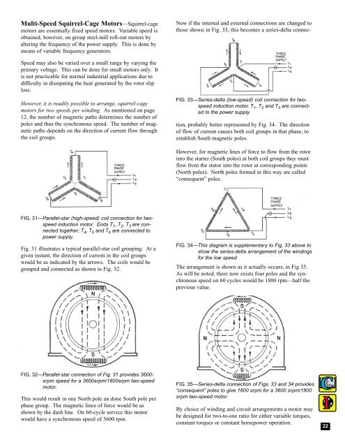
Multi-Speed Squirrel-Cage <strong>Motors</strong>—Squirrel-cagemotors are essentially fixed speed motors. Variable speed isobtained, however, on group steel-mill roll-out motors byaltering the frequency of the power supply. This is done bymeans of variable frequency generators.Speed may also be varied over a small range by varying theprimary voltage. This can be done for small motors only. Itis not practicable for normal industrial applications due todifficulty in dissipating the heat generated by the rotor sliploss.However, it is readily possible to arrange, squirrel-cagemotors for two speeds per winding. As mentioned on page12, the number of magnetic paths determines the number ofpoles and thus the synchronous speed. The number of magneticpaths depends on the direction of current flow throughthe coil groups.FIG. 33—Series-delta (low-speed) coil connection for twospeedinduction motor. T 1 , T 2 and T 3 are connectedto the power supply.Now if the internal and external connections are changed tothose shown in Fig. 33, this becomes a series-delta connection,probably better represented by Fig. 34. The directionof flow of current causes both coil groups in that phase, toestablish South magnetic poles.However, for magnetic lines of force to flow from the rotorinto the starter (South poles) at both coil groups they mustflow from the stator into the rotor at corresponding points(North poles). North poles formed in this way are called“consequent” poles.FIG. 31—Parallel-star (high-speed) coil connection for twospeedinduction motor. Ends T 1 , T 2 , T 3 are connectedtogether; T 4 , T 5 and T 6 are connected topower supply.Fig. 31 illustrates a typical parallel-star coil grouping. At agiven instant, the direction of current in the coil groupswould be as indicated by the arrows. The coils would begrouped and connected as shown in Fig. 32.FIG. 34—This diagram is supplementary to Fig. 33 above toshow the series-delta arrangement of the windingsfor the low speed.The arrangement is shown as it actually occurs, in Fig 35.As will be noted, there now exists four poles and the synchronousspeed on 60 cycles would be 1800 rpm—half theprevious value.FIG. 32—Parallel-star connection of Fig. 31 provides 3600-srpm speed for a 3600srpm/1800srpm two-speedmotor.This would result in one North pole an done South pole perphase group. The magnetic lines of force would be asshown by the dash line. On 60-cycle service this motorwould have a synchronous speed of 3600 rpm.FIG. 35—Series-delta connection of Figs. 33 and 34 provides“consequent” poles to give 1800 srpm for a 3600 srpm/1800srpm two-speed motor.By choice of winding and circuit arrangements a motor maybe designed for two-to-one ratio for either variable torques,constant torques or constant horsepower operation.22