THEABCOF LARGEINDUCTION MOTORS<strong>Induction</strong> <strong>Motors</strong> are the “work-horses” of modernindustry. This is particularly true in the medium and highspeeds, because as shown in this article, the power factorand efficiency, above 500 rpm, are quite acceptable for mostapplications.The ruggedness and simplicity of squirrel-cage motorsmakes them a first choice where constant speed is acceptable.The every-day needs of industry find squirrel-cagemotors filling almost every conceivable constant-speed driverequirement.Where speed control or frequent reversing is desired, orwhere high controllable torque and extra-low starting currentmust be associated, wound-rotor (slip-ring) inductionmotors are used.Many designs and types of induction motors, some ofthem extremely special, are required to supply all needs ofindustry. The construction, operation, application and controlof the more common ones are discussed in this article.Mr. G. L. Oscarson, the author of this special issue of the E-M Synchronizer is therecipient of two Electrical Engineering degrees from the Institute of Technology,University of Minnesota. Specializing in electrical power apparatus, Mr Oscarsonwas for seventeen years directly associated in the field with the industrial applicationof motors, generators and controls. He has been Chief Application Engineer of theElectric Machinery Mfg. Company, since 1940, responsible for the coordination ofapplication requirements of large power apparatus. This paper is one of many Mr.Oscarson has prepared both for publication for presentation to engineering groups.Mr. Oscarson is a Fellow and Life Member of A.I.E.E., a member of the CementIndustry Committee of A.I.E.E., a member of the Electrical Engineering Committee ofTAPPI, a registered Professional Engineer.TABLE OF CONTENTS:Part 1 Fundamentals of AlternatingCurrent and <strong>Induction</strong> <strong>Motors</strong>Alternating-Current Formulas . . . . . . . . . .5Power Factor and Magnetizing Current . . .6Torque, Synchronous Speeds, Slip,Efficiency, Horsepower Determination . .7, 8, 9Insulation and Temperature Rise . . . . . . . .9Protective Constructions . . . . . . . . . . . . .10Mechanical Constructions . . . . . . . . . . . .11Part 2 How the <strong>Induction</strong> MotorOperates; Torque Characteristics;Construction FeaturesExplanation of Operation . . . . . . . . . . . . .12Torque . . . . . . . . . . . . . . . . . . . . . . . . . .13Rotor Construction . . . . . . . . . . . . . . 14, 15Construction Features . . . . . . . . . . . . 16, 17Part 3 Application and StartingMethods for <strong>Induction</strong> <strong>Motors</strong>Squirrel-Cage Motor Classifications . . . .18Starting Current of Squirrel Cage <strong>Motors</strong> .19Reduced Kva Starting . . . . . . . . . . . . . . .20Methods of Starting . . . . . . . . . . . . . . . .21Multi-Speed Squirrel-Cage <strong>Motors</strong> . . . . .22Wound-Rotor <strong>Induction</strong> <strong>Motors</strong> . . . . . . .23Speed and Starting Characteristicsof Wound-Rotor <strong>Motors</strong> . . . . . . . . . . .24, 25Part 4 <strong>Induction</strong> Motor Control;Adjustable-Speed Magnetic DriveSquirrel-Cage Motor Control . . . . . . . 26, 27Wound-Rotor Motor Control . . . . . . . 26, 28Adjustable-Speed Magnetic Drive . . . . . .284
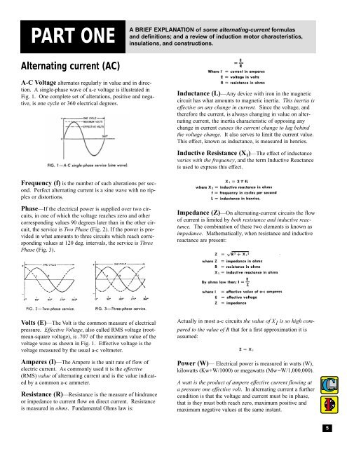
PART ONEA BRIEF EXPLANATION of some alternating-current formulasand definitions; and a review of induction motor characteristics,insulations, and constructions.Alternating current (AC)A-C Voltage alternates regularly in value and in direction.A single-phase wave of a-c voltage is illustrated inFig. 1. One complete set of alterations, positive and negative,is one cycle or 360 electrical degrees.Inductance (L)—Any device with iron in the magneticcircuit has what amounts to magnetic inertia. This inertia iseffective on any change in current. Since the voltage, andtherefore the current, is always changing in value on alternatingcurrent, the inertia characteristic of opposing anychange in current causes the current change to lag behindthe voltage change. It also serves to limit the current value.This effect, known as inductance, is measured in henries.Inductive Resistance (X 1 )—The effect of inductancevaries with the frequency, and the term Inductive Reactanceis used to express this effect.Frequency (f) is the number of such alterations per second.Perfect alternating current is a sine wave with no ripplesor distortions.Phase—If the electrical power is supplied over two circuits,in one of which the voltage reaches zero and othercorresponding values 90 degrees later than in the other circuit,the service is Two Phase (Fig. 2). If the power is providedin what amounts to three circuits which reach correspondingvalues at 120 deg. intervals, the service is ThreePhase (Fig. 3).Impedance (Z)—On alternating-current circuits the flowof current is limited by both resistance and inductive reactance.The combination of these two elements is known asimpedance. Mathematically, when resistance and inductivereactance are present:Volts (E)—The Volt is the common measure of electricalpressure. Effective Voltage, also called RMS voltage (rootmean-squarevoltage), is .707 of the maximum value of thevoltage wave as shown in Fig. 1. Effective voltage is thevoltage measured by the usual a-c voltmeter.Amperes (I)—The Ampere is the unit rate of flow ofelectric current. As commonly used it is the effective(RMS) value of alternating current and is the value indicatedby a common a-c ammeter.Resistance (R)—Resistance is the measure of hindranceor impedance to current flow on direct current. Resistanceis measured in ohms. Fundamental Ohms law is:Actually in most a-c circuits the value of X 1 is so high comparedto the value of R that for a first approximation it isassumed:Power (W)— Electrical power is measured in watts (W),kilowatts (Kw+W/1000) or megawatts (Mw=W/1,000,000).A watt is the product of ampere effective current flowing ata pressure one effective volt. In alternating current a furthercondition is that the voltage and current must be in phase,that is they must both reach zero, maximum positive andmaximum negative values at the same instant.5