PART TWOHOW THE INDUCTION MOTOR OPERATES:Torque Characteristics of the Rotor Winding.Magnetic Lines of Force (commonly called flux) surroundany conductor carrying current. This results in amagnetic field of definite strength depending on the amountof current flowing in the conductor and the nature of themagnetic circuit, that is the iron path available for flux adjacentto the conductor. The magnetic field has a definitepolarity depending on the direction of current. Thus themagnetic field surrounding a conductor carrying alternatingcurrent varies both in strength and direction. It pulsates, atline frequency, from maximum in one direction to maximumin the opposite direction. For explanatory purpose considera two-pole motor with 6 stator slots as shown on the oppositepage.If twelve conductors, properly connected, are placed in thesix equally spaced slots on the inner periphery of a laminatedsteel ring (called a stator) and are connected to a 3-phasesupply, they will produce, in effect, a rotating magneticfield. The magnetic field will be substantially uniform intotal strength, but will rotate in space as described later.The seven diagrams on page 13 show the dispositionof electrical currents and magnetic fields in the stator of a 3-phase squirrel-cage motor, for regular intervals numbered 0to 6, and comprising one-half cycle of a full alternating currentwave.As the alternating currents change in value and direction themagnetic field, in effect, rotates clockwise about the stator;the lines of force thus cutting across the squirrel-cage barsin the rotating element (called a rotor). These bars are allelectrical conductors and are connected by short-circuitingrings. The magnetic lines of force represented by the coloreddash lines may be assumed to pass through the air-gapat right angles to the face of the rotor.If the torque developed causes the rotor to turn, it will accelerateto some definite speed at which the turning effort isequal to the retarding effort or load.If very little load is imposed, say only friction and windageof the rotor, only a slight amount of current need flow in thesquirrel-cage bars to develop that torque. Only a very slightamount of relative motion (slip) between the rotating magneticfield and the rotor is required to induce this amount ofcurrent. The rotor will therefore turn at nearly synchronousspeed at no load.However, even to overcome only friction and windage somedefinite torque is required. To develop this there must besome current inducted in the rotor bars, however slight.This necessitates some slip even at no load and thereforesynchronous speed cannot quite ever be reached.By reversing any two of the leads of a 3-phase motor, thephase rotation will be reversed. Instead of A, B, C, as inFig. 3, page 5 it would become A, C, B. This would causethe magnetic field to build up to reverse order and rotatecounter-clockwise.Synchronous Speed, as stated previously, variesinversely as the number of stator poles. The stator representedon the opposite page is that of a two-pole motor. Thewinding is so arranged that the resultant flux leaves the statorat one point (a North Pole) and re-enters the stator at adirectly opposite point (a South Pole). If the windingswould be arranged for four poles, the flux would leave thestator at two points and re-enter at two points. The fluxpaths for a 4 pole motor are shown in Fig. 16. Stator windingscan be arranged to have 2, 4, 6, or any other practicablenumber of poles in multiples of two.As long as the rotor remains stationary the motor is, for allpractical purposes, a transformer with a short-circuited secondarywinding. The rotor bars constitute the secondary.Currents of considerable magnitude, alternating at line frequency,flow in these bars. The are induced by the magneticlines of force cutting across the bars. As is well known, aconductor in a magnetic field and carrying current will haveexerted on it a force tending to move it at right angles to themagnetic field. A tangential force, or torque, is thus exertedon the rotor periphery.The direction of this torque causes the rotor to attempt toturn in the same direction as the magnetic field in the statoris rotating; in this case clockwise. The amount of torquedeveloped depends on the power consumed as resistancelosses in the cage bars of the rotor, that is it depends on theI 2 R losses.FIG. 16 – Diagram of paths of magnetic flux (dashed lines)for four pole motor. <strong>Induction</strong> motors can be built with anypractical number of pairs of poles.12
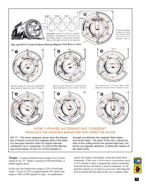
HOW 3-PHASE ALTERNATING CURRENTPRODUCES THE ROTATING MAGNETISM THAT SPINS THE ROTORFIG 17 – The seven diagrams above show the dispositionof electric currents and magnetic field of the statorof a two-pole induction motor for regular intervalsnumbered 0 to 6, comprising 1/2 cycle of the alternating-currentwaves. As the a-c current changes instrength and direction the magnetic field rotatesaround the stator. The poles of the rotor, induced bylines of flux cutting across the squirrel-cage bars, areforced, by magnetic attraction, to follow the rotation ofthe stator poles.Torque—A typical induction motor torque curve is representedin Fig. 18. Torque, in percent of full-load torque, isplotted against speed.In this case, the locked-rotor torque is 125% of full-loadtorque. It rises to 225% at approximately 85% speed, anddrops to 100% at 98% speed (2% slip). At synchronousspeed, zero torque is developed, as has previously beenmentioned. If the rotor is driven above synchronous speedit will continue to draw a magnetizing current componentfrom the line but will deliver a power component. It willtherefore operate as an induction generator, delivering fullload at normal full-load slip (in this case a negative slip).13