CXA-P1212C-WJL
CXA-P1212C-WJL
CXA-P1212C-WJL

You also want an ePaper? Increase the reach of your titles
YUMPU automatically turns print PDFs into web optimized ePapers that Google loves.
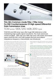
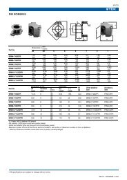
The specifications may be changed without any notice.When placing orders,please confirm "Specifications" or "Product Drawing" through TDK sales or distributors.FeaturesThis inverter is for two lamps. It has Dimming function(PWM System) and Remote func tion.This product has shutdown function.It prevents from keeping generating the high voltage when the lamps open.(Refer Note.3-4.)With lamp failure detector.Normal Operation : CN1-8=0VSome Lamps Open : CN1-8=5VSelect the way of dimming (between CN1-6 and CN1-7)1. Insert a potentiometer (0-50kΩ)2. Apply the voltage (0-2.5V)The high-voltage area (terminals and patterns) is coated with silicone so as to avoid the d efects caused by dust.[1] Outline1-1. OutlineTOP VIEWLabel (Examlpe)TDK part No, Date code, Country of origin3.5±0.510.25±0.5107±0.3153.5 max.(10.0)(iii)(4.0)T1122 max.14±0.31CN1L1<strong>CXA</strong>-<strong>P1212C</strong>-<strong>WJL</strong>1415MADE IN JAPANCAUTIONHIGH VOLTAGECN2(4.0)(ii)(10.0)2-φ3.5±0.2(i)SILICONENo parts and pattern area.(Except GND)SIDE VIEW8.5max.(1.0)75mm(a:High Voltage generation area)BOTTOM VIEWUnit:mmWeight:20.0g.typ.No.(i)(ii)(iii)Part DescriptionPCBInput Connector CN1Output Connector CN2MaterialConposite (CEM-3)53261-0790SM03(7-D1)B-BHS-1QU REMARKMATES WITH1 UL94V-0 t=1.0-1 MOLEX51021-07001 JSTBHR-04VS-1TDK CORPORATIONPRODUCT NAME or MODEL,TITLEDC-AC INVERTER <strong>CXA</strong>-<strong>P1212C</strong>-<strong>WJL</strong>NAME OF DRAWINGDRAWING No.PRODUCT DRAWINGCTR-0929-DPAGE2
Example of naming productC X A - P 1 2 1 2 C - W J LInverter.CN2 high voltage output side terminal position :L-Leftside sees from insert terminal.Output power : 8~9W.Output connector : J-SM03(7-D1)B-BHS-1(JST)Output current : 6mArms x2 type.Input voltage :12V type.Adjustment of brightness method :Duty control method to put current feedback.Selectable dimming function :Voltage dimming or Variable resistance dimming.Version1-2. Connector ConfigurationInput side CN1Output side CN2Pin No.SymbolsRatingsNotesPin No.SymbolsRatingsNotesCN1-1CN1-2CN1-3CN1-4CN1-5VinGNDVrmt10.8-13.2V0V0-0.4V:OFF2.5-Vin V:ONInput VoltageGNDRemote InputVoltageCN2-1CN2-2CN2-4VHIGH1VHIGH2VLOW600Vrms600Vrms(2V)Output1Output2CN2-3 NC --Output1 ReturnCN1-6Vst0V / 5VThe warningoutput5V in abnormalcircumstancesCN1-7Vbr/Rbr0-2.5V/0-50kΩControl/VRNote1-1. Marking of TDK part No, Date code, Country of origin.1) TDK part No., Date code, Country of origin, is marked on the trans former.2) Date code example. (ex. APR. 15. 2001)1 4 1 5Two digits of production day.One digit of production month. (Oct. : X, Nov. : Y, Dec. : Z).Last digit of production year.3) Country of origin code example. (ex. MADE IN JAPAN. MADE IN CHINA).TDK CORPORATIONPRODUCT NAME or MODEL,TITLEDC-AC INVERTER <strong>CXA</strong>-<strong>P1212C</strong>-<strong>WJL</strong>NAME OF DRAWINGDRAWING No.PRODUCT DRAWINGCTR-0929-DPAGE3
Note1-2. For circuit connection, please prefer to test circuit dia gram [3].Note1-3. Please use minimum of 2mm clearance (all directions) between inverter high voltage ar ea and any conductors.Please refer to mechanical drawing for marking of high voltage area.Note1-4. Open voltage (strike voltage) is measured across the transformer secondary winding at no loa d as the reading atthe output connector would be less than the actual value.Note1-5. If the start up voltage falls below Cold Cathode Tube strike voltage, the CCFL will not light up easily special ly atlower ambient temperature. Please review mounting instruction to avoid any abnormal op eration due tocoupling/leakage capacitance of inverter high voltage area to any surrounding conductor.Note1-6. Please check your lamp characteristic for minimum operational current and set the limit point in your design toavoid flickering and/or abnormal operation.Note1-7. For proper operation of circuit protection (fuse or IC PROTECTOR),Please use minimum of 2A capaci ty for inputpower supply.Note1-8. For proper operation: Don't connect the out put VLOW(CN2-4) terminal to the in put GND(CN1-3,4).[2]Absolute maximum ratingsItems Symbols Specification Unit NotesInput VoltageVin 0~15Vrmt -1~Vin+1Vbr 0~16VLoad ResistanceRL//CL100 // 5kΩ // pFOperating Temp. rangeTa-10~70°CStorage Temp. rangeTs-30~85°CHumidity rangeRH95%RHA maximum wet ball temperature is 38°CNo dew.Note2-1.The test circuits added 5pF capacitor across the load resistor for LCD back light stay ca pacitor.TDK CORPORATIONPRODUCT NAME or MODEL,TITLEDC-AC INVERTER <strong>CXA</strong>-<strong>P1212C</strong>-<strong>WJL</strong>NAME OF DRAWINGDRAWING No.PRODUCT DRAWINGCTR-0929-DPAGE4
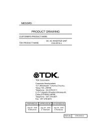
[3] Test circuitVbr0~2.5VVin10.8~13.2VVrmt5VVAVIinVab SW1VstaVb SW2FCN1-1CN1-2CN2-1CN1-3CN1-4T1-2CN1-5T1CN2-2T1-7,8CN1-6CN1-7FdutyRbrF0~50kΩ(0.025W min.)*For the number of the component's positon, please refer to Outline diagram [1].F1IC7 814CN2-41000:1PROBESW3SW4RL2Io2SW5AVopenRL1CL2Io1RL1,2:Load resistance (7W MIN.)CL1,2:Stray capacitor (3kV MIN.)AVCL1Note.3-1.SW1(ON/OFF) Operation is as fol lowing;SW1Operation of unitNote.3-2.SW2(ON/OFF) Operation is as fol lowing;SW2Operation of unitabOpenOperationNon operationNon operationab*Voltage dimmingVbr=0~2.5V*Variable resistance dimmingVR=0~50kΩ*Vbr=0V:brightness MAX.Rbr=0Ω:brightness MAX.Note3-3.Test EquipmentsV Digital Multiple Meter(ADVANTEST R6451A or equivalent)AFV~A~DC Current Meter(ADVANTEST R6451A or equivalent)Frequency Countor(ADVANTEST R6451A or equivalent)True RMS Meter(KEITHLEY 2001 or equivalent.)High Frequency Current Meter(KEITHLEY 2001 or equivalent)1000:1 High Voltage Probe(Tektronix P3000 or equivalent)Connection diagram of LCD module (Reference)LCD moduleDC/AC inverterNote3-4.Safety FunctionLoad ConditionNormal Operation1 Lamp Open2 Lamps Open*1 Alarm Signal(CN1-6)0.5V max.4.75~5.25V4.75~5.25V*2 ShutdownOperationNormalNormalShutdown*1. If the inverter detects open circuit all lampsfor more than 3 seconds it will shut down.*2. In test circuit[3] ,If anyone of switches SW3~SW5 opens,then the warning signal will be activated (+5V).LampLampTDK CORPORATIONAVLOWVHIGHVHIGH*Connect the High Frequency Current Meter to the Low-Voltage (VLOW) side.NAME OF DRAWINGPRODUCT DRAWINGPRODUCT NAME or MODEL,TITLEDC-AC INVERTER <strong>CXA</strong>-<strong>P1212C</strong>-<strong>WJL</strong>DRAWING No.CTR-0929-DPAGE5
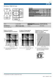
Remote terminal circuit (Reference)CN1-1,2VinCN1-5Vrmt20kΩ10kΩ10kΩ10kΩIC1Io1, Io2 (mArms)Dimming characteristic (Reference)6.05.04.03.02.01.000 0.5 1.0 1.5 2.0 2.5Vbr (V)Brightness ratio characteristic(Reference)806040203.000 0.5 1.0 1.5 2.0 2.5Vbr (V)Brightness ratio (%)1003.0[4] Electrical specificationsItemOutput Current(Brightness MAX.)Output Current(Brightness MIN.)Input Current1Input Current2FrequencyOpen Circuit VoltageWarning Signal(Note7)Symbollo1/2lo1/2lin1lin2F1VstVin(V)12±1.212±0.612±0.6Vopen 10.812±1.212±1.212±1.2Vrmt(V)5±0.255±0.255±0.255±0.255±0.25ConditionsVbr(V)/Ta(°C)VR(kΩ)0 / 00 / 00 / 00 / 00 / 0-10~7023±512±1.2 5±0.25 2.5 / 50 -10~7012±0.612±0.612±0.65±0.255±0.250±0.255±0.255±0.252.5 / 500 / 00 / 00 / 023±5-10~70-10~70-10~70Frequency(Duty) F2 12±0.6 5±0.25 2.5 / 50 -10~700 / 0-10~70-10~70-10~70-10~70RL1(kΩ )//CL1(pF)RL2(kΩ )//CL2(pF)85~95 // 585~95 // 590 // 590 // 585~95 // 585~95 // 585~95 // 585~95 // 590 // 590 // 585~95 // 585~95 // 585~95 // 585~95 // 585~95 // 585~95 // 5∞∞85~95 // 5∞∞85~95 // 585~95 // 585~95 // 5MIN.5.35.54.54.5-SpecificationsTYP.6.06.05.05.0MAX.6.76.51.1 2.0 2.91.2 2.0 2.838 43 485.55.50 0.5UnitmA rms- 0.8 1.0 A- - 1 mAkHz220 250 280 Hz1.5 1.7 - kVrmsVTDK CORPORATIONPRODUCT NAME or MODEL,TITLEDC-AC INVERTER <strong>CXA</strong>-<strong>P1212C</strong>-<strong>WJL</strong>NAME OF DRAWINGDRAWING No.PRODUCT DRAWINGCTR-0929-DPAGE6
[5] Reliability testFollowing test items are assured.ItemsLow Temp.NonoperationalLow Temp.operationalHigh Temp.NonoperationalHigh Temp.operationalHeat shockHumidity(Non operational)Conditions-30°C 500h-10°C 500hLoad cond.:TYP85°C 500h70°C 500hLoad cond.:TYP-20°C to 75°C30min.Each 100 Cycles60°C 90~95%RH 500hJudgementElectrical and apperrance should be in thespec.Vibration10~57Hz Amplitude 0.75mm58~500Hz 1GSweep:11min60min each axis X,Y,ZShock100G 11msHarf-sine pulse1 time each axis ±X,Y,ZTDK CORPORATIONPRODUCT NAME or MODEL,TITLEDC-AC INVERTER <strong>CXA</strong>-<strong>P1212C</strong>-<strong>WJL</strong>NAME OF DRAWINGDRAWING No.PRODUCT DRAWINGCTR-0929-DPAGE7
[6] Packing and MarkingA shipping box is packaged to avoid from water or damage. Following items are printed on th e box.6-1.6-2.6-3.6-4.6-5.6-6.TDK part No.ManufactureCustomer part No.QTY.Inspection No.Country of origin<strong>CXA</strong>-<strong>P1212C</strong>-<strong>WJL</strong>TDKAnti static bag10pcs / boxMarking TDK Part No. Manufacture Customer Part No. QTY. Inspection No. Countory of origin10pcs/Inner box 10100pcs/Outer cartonInner box(237mm:L)(223mm:W )(40mm:H)MarkingTDK Part No.ManufactureCustomer Part No.QTY.Inspection No.Countory of originOuter carton(500mm:L)(244mm:W )(234mm:H)[7] Others7-1. Test cond.A normal test condition :Temperature (20±15°C), Humidity (65±20%RH).7-2. Std warrantryOne year after shipment.This covers any defects in material or workmanship.Defective units will be replaces at no charge.7-3. OthersTDK and customer are to discuss changes,problems, and modifications and etc, when needed.TDK CORPORATIONPRODUCT NAME or MODEL,TITLEDC-AC INVERTER <strong>CXA</strong>-<strong>P1212C</strong>-<strong>WJL</strong>NAME OF DRAWINGDRAWING No.PRODUCT DRAWINGCTR-0929-DPAGE8