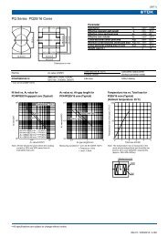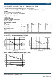
CXA-M10L-L
CXA-M10L-L
CXA-M10L-L
- No tags were found...

You also want an ePaper? Increase the reach of your titles
YUMPU automatically turns print PDFs into web optimized ePapers that Google loves.
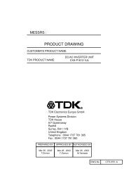
MESSRS :PRODUCT DRAWINGCUSTOMER'S PRODUCT NAME:TDK PRODUCT NAME:DCAC INVERTER UNIT<strong>CXA</strong>-<strong>M10L</strong>-LTDK CorporationCorporate Headquarters13-1,Nihonbashi 1-chome,Chuo-ku,Tokyo 103, JAPANTelephone : 03-3278-51112-15-7,Higashi-Ohwada,Ichikawa-shi,Chiba,272-8558 JAPANTelephone : 047-378-9671Fax : 047-378-9673RPREPARED BY APPROVED BY AUTHORIZED BYSep.08 , 2005H.MitsumotoSep.08 , 2005E.TakahashiSep.08 , 2005K.HanabusaDWG.No.CTR-0743-C
Precautionary Notes Regarding the Use of This InverterWhen using this product, give due consideration to the precautionary notes described below andensure a safe design. Inappropriate use may result in electric shock, injury or fire.Warning This product is subject to high voltage. Do not touch it while the power is on.Failing to do so may result in electric shock.Caution This product is designed for the lighting of a Cold Cathode Fluorescent Lamp.Do not use it with any other load. Store this product under the conditions defined in the specification document. Do not store this product in an environment where dust, dirt or corrosive gas(salt,acid,base, etc.) is present. This product is subject to high voltage. If there is a possibility that the user may touch the product,provide a proper indication in order to draw the user's attention. This product is designed for use with general electronic equipment.If it is to be used with medical equipment that directly affects human life or for the control oftransportation equipment to which passengers entrust their lives, provide thorough fail-safe measures. Avoid using this product under high temperatures or high humidity or in an environment in whichdust, dirt or any corrosive gas (salt,acid,base, etc.) is present.Also,be careful not to allow the formation of dew condensation. It may result in damage or electric shock. If the product does not have a built-in protective circuit (circuit breaker, fuse, etc.),it is recommended that a fuse be used at the input stage to prevent the generation ofsmoke or fire in the event of a malfunction.Even when the product has a built-in protective circuit (circuit breaker, fuse, etc.),the circuit may not function properly due to inappropriate operating conditions or power-supply capacity.It is recommended that an appropriate protective circuit (circuit breaker, fuse, etc.)be provided separately from the built-in circuit. Use the product only within the specified input voltage, output power, output voltageand operating temperature ranges. Exceeding these values may result in damage, etc. Provide a measure for the prevention of surge voltage due to lightning, etc.Abnormal voltage may result in damage, etc. To prevent problems arising from short-circuiting of the high-voltage section,provide appropriate measures to prevent the entry of foreign substances following installation. This product is not designed to provide resistance to radiation. Ripples could be superimposed on the voltage and the current in the input source connected to the inverter , depending on the impedance in the input source, wiring, etc.When you select an input source, please check waveforms, etc on the final set.Handling Precautions This product uses thin wires. Observe the following precautions and handle it with care soas not to cause wire breakage. Broken wire may result in damage, etc. Do not stack multiple products on top of one another. Do not allow the product to come in contact with tools, etc. Do not apply excessive stress during installation.It may cause chipping and cracking,resulting in damage, etc. Provide a clearance of 2 mm or more between the high-voltage section of this product andthe frame body on which the product is installed and also the conductor section (pattern , pad etc. ). Please do not use the product, when dropping it, since there is a possibility of the parts damage.Please confirm abnormality is not found in the product enough when using it by any chance.TDK CORPORATIONPRODUCT NAME or MODEL,TITLEDC-AC INVERTER UNIT <strong>CXA</strong>-<strong>M10L</strong>-LNAME OF DRAWINGDRAWING No.PRODUCT DRAWINGCTR-0743-CPAGE1
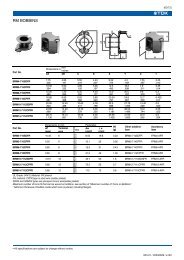
The specifications may be changed without any notice.When placing orders,please confirm "Specifications" or "Product Drawing" through TDK sal es or distributors.FeaturesThis inverter is for one or two lamps. (changed by the connection.)This inverter is the mount board.This product is conformity to RoHS directive.()Conformity to RoHS Directive:This means that, in confor mity with EU Directive 2002/95/EC,lead, cadmium, hexavalent chromium, and specific bromine-based flame retardants, PBBand PBDE, have not been used,except for exempted applications.[1] Outline1-1. Outline(i)29 max.24±0.2±0.2 ±0.210.16 10.16(ii)(6.5)VINE CQ1L1BJ2CQ2E B(TOP VIEW)R1 R2C3OUTGNDOUT256 max.50.8±0.5φ2±0.15φ2.5±0.1533.5±0.2GNDC1J1Label (Examlpe)TDK part No, Date code, Country of originT1jumperC2OUT1(v) (iv) (iii)0.5±0.2(BOTTOM VIEW)2-R1±0.15 min. 14.5 max.(1.2)2 max.5-φ0.8±0.1 or 5- 0.64±0.07(Tin plated obstinate copper wire)(SIDE VIEW)<strong>CXA</strong>-<strong>M10L</strong>-LCHINAa:30mm(a:High Voltage generation area)Unit:mmWeight:21.0g.typ.Please secure the air clearance of 2mm or more from the high voltage generation area up and down and right and left. Please refer to Note1-4. for details.1-2. Connector configurationPin No.(i)(ii)(iii)(iv)(v)ConnectionSymbol RatingVin12VGND0VOUT1 400Vrms/5mArmsOUT2 400Vrms/5mArmsOUT GND0VNotesPRODUCT NAME or MODEL,TITLEDC-AC INVERTER UNIT <strong>CXA</strong>-<strong>M10L</strong>-LNAME OF DRAWINGDRAWING No.TDK CORPORATIONPRODUCT DRAWINGCTR-0743-CPAGE2
Note1-1. Marking of TDK part No, Date code, Country of origin.1) TDK part No., Date code, Country of origin, is marked on the side of transformer.2) Date code example. (ex. APR. 2005)5 4R3) Country of origin code example. (ex. JAPAN. CHINA).Product Conforming to RoHS DirectiveBlankNote1-2. For circuit connection, prefer to test circuit diagram [4].Identification signOne digit of production month. (Oct. : X , Nov. : Y , Dec. : Z)Last digit of production year.()Conformity to RoHS Directive:This means that, in confor mity with EU Directive 2002/95/EC,lead, cadmium, hexavalent chromium, and specific bromine-based flame retardants, PBBand PBDE, have not been used,except for exempted applications.Note1-3. For operation in floating mode, please remove the jumper(J1) on to p side of PCB that pin(ii) and pin (v).Note1-4. Please use minimum of 2mm clearance (all directions) between inverter h igh voltage area(a) and any conductors.Please refer to mechanical drawing for marking of high voltage area.Note1-5. To prevent electrical discharge from high voltage area, please use non-conductive fastener in U mounting hole.Note1-6. Open voltage (strike voltage) is measured across the transformer secondary winding at no load as the reading atthe output connector would be less than the actual value.Note1-7. If the start up voltage falls below Cold Cathode Tube strike voltage, the CCFL will not light up easily specially atlower ambient temperature. Please review mounting instruction to avoid any abnormal operation due tocoupling/leakage capacitance of inverter high voltage area to any surrounding conductor.[2] Absolute maximum ratingsItem Symbol Specification Unit NotesInput VoltageVin0~14.4VOutput PowerPout6WOperating Temp. rangeTa-10~60°CStorage Temp. rangeTs-20~85°CHumidity rangeRH95%RHA maximum wet ball temperature is 38°CNo dewPRODUCT NAME or MODEL,TITLEDC-AC INVERTER UNIT <strong>CXA</strong>-<strong>M10L</strong>-LNAME OF DRAWINGDRAWING No.TDK CORPORATIONPRODUCT DRAWINGCTR-0743-CPAGE3
[3]Electrical specificationsConnectionItemOutput CurrentSymbolIoutConditionsVin [V] Ta [°C] RL [kΩ]12±0.12 23±5 4012±0.6 -10~60 30~50MIN.9SpecificationTYP.10MAX.118 10 12UnitmArms1Input CurrentFrequencyIinF12±0.6 -10~60 30~5012±0.6-10~6030~50-230.42280.6333AkHzOpen Circuit VoltageVopen12±0.6-10~60∞1.01.2-kVrmsOutput CurrentIout12±0.12 23±5 6712±0.6 -10~60 50~845.1 6 6.44.4 6 7.1mArms2Input CurrentFrequencyIinF12±0.6 -10~60 50~84 - 0.27 0.4112±0.6-10~6050~84263136AkHzOpen Circuit VoltageVopen12±0.6-10~60∞1.01.2-kVrmsOutput CurrentIout12±0.12 23±5 8012±0.6 -10~60 60~1004.3 5 5.53.8 5 6.0mArms3Input CurrentFrequencyIinF12±0.6 -10~60 60~100 - 0.23 0.3512±0.6 -10~60 60~100 23 28 33AkHzOpen Circuit VoltageVopen12±0.6 -10~60 ∞ 1.0 1.2 -kVrmsOutput CurrentIout1,Iout212±0.12 23±5 RL1=RL2=8012±0.6 -10~60 60~1004.5 5 5.54 5 6mArms4Input CurrentFrequencyIinF12±0.6 -10~60 60~10012±0.6-10~6060~100-230.42280.6333AkHzOpen Circuit VoltageVopen12±0.6-10~60∞1.01.2-kVrmsTDK CORPORATIONPRODUCT NAME or MODEL,TITLEDC-AC INVERTER UNIT <strong>CXA</strong>-<strong>M10L</strong>-LNAME OF DRAWINGDRAWING No.PRODUCT DRAWINGCTR-0743-CPAGE4
[4] Test circuitConnection Test circuit Notes 1 Short of OUT1,OUT2 2 Open of OUT1 or OUT23Short of OUT2,OUT GND 4 Note4-1.Test EquipmentsVAFV~A~Digital Multiple Meter(ADVA NTEST R6451A or equivalent)DC Current Meter(ADVANTEST R6451A or equivalent)Frequency Countor(ADVANTES T R6452A or equivalent)True RMS Meter(KEITHLEY 2001 or equivalent.)High Frequency Current Mete r(KEITHLEY 2001 or equivalent)1000:1 High Voltage Probe(Tektronix P3000 or equivalent)PRODUCT NAME or MODEL,TITLEDC-AC INVERTER UNIT <strong>CXA</strong>-<strong>M10L</strong>-LNAME OF DRAWINGDRAWING No.TDK CORPORATIONPRODUCT DRAWINGCTR-0743-CPAGE5
[5] Reliability testFollowing test items are assured.ItemLow Temp.NonoperationalLow Temp.operationalHigh Temp.NonoperationalHigh Temp.operationalCondition-40°C 96h-10°C 96hLoad cond.:TYP85°C 96h60°C 96hLoad cond.:TYPJudgementHeat shockHumidity(Non operational)The following 5 cycles,Load cond.:TYP60°C20°C-10°C2h/div40°C 90~95%RH 96hElectrical and apperrance should be in thespec.Vibration10~55Hz Amplitude 0.35mm or 5GSweep:1min30min each axis X,Y,ZShock60G 6ms Harf-sine pulse1 time each axis ±X,Y,ZTerminal strengthHeatresistance of solderlingTensile:1kgf 10sec260°C±5°C 10sec350°C±10°C 3secState of soldering230°C±5°C 5secElectrical and apperrance should be in thespec.Thing that lead wire which solders and isextinguished is covered with new solder.TDK CORPORATIONPRODUCT NAME or MODEL,TITLEDC-AC INVERTER UNIT <strong>CXA</strong>-<strong>M10L</strong>-LNAME OF DRAWINGDRAWING No.PRODUCT DRAWINGCTR-0743-CPAGE6
[6] Packing and MarkingA shipping box is packaged to avoid from damage. Fo llowing items are printed on the box.6-1.6-2.TDK part No.Manufacture<strong>CXA</strong>-<strong>M10L</strong>-LTDK6-3.6-4.6-5.6-6.Customer part No.QTY.Inspection No.Country of originPacking style as under Fig. (300 going in with a standard.)StyrofoamProductCorrugated cardboardStyrofoam 60pcs in one tray X 5trays=300pcs/one boxPacking box.(210mm)(480mm)(340mm)TDKa part No.ManufactureCustomer part No.QTY.Inspection No.Countory of origin[7] Others7-1.Test cond.A normal test condition :Temperature (20±15°C), Humidity (65±20%RH).7-2. Std warrantryOne year after shipment.This covers any defects in material or workmanship.Defective units will be replaces at no charge.7-3.OthersTDK and customer are to discuss changes,problems, and modifications and etc, when needed.PRODUCT NAME or MODEL,TITLEDC-AC INVERTER UNIT <strong>CXA</strong>-<strong>M10L</strong>-LNAME OF DRAWINGDRAWING No.TDK CORPORATIONPRODUCT DRAWINGCTR-0743-CPAGE7