Bailey Technical Catalogue - Safety Systems UK Ltd
Bailey Technical Catalogue - Safety Systems UK Ltd
Bailey Technical Catalogue - Safety Systems UK Ltd

You also want an ePaper? Increase the reach of your titles
YUMPU automatically turns print PDFs into web optimized ePapers that Google loves.
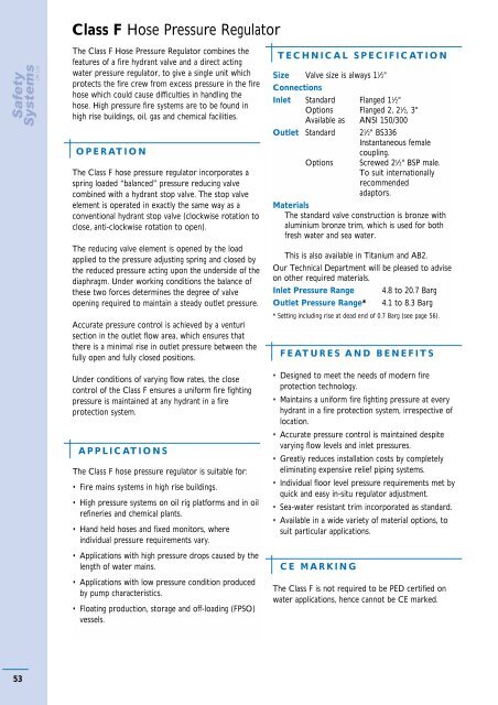
Class F Hose Pressure RegulatorThe Class F Hose Pressure Regulator combines thefeatures of a fire hydrant valve and a direct actingwater pressure regulator, to give a single unit whichprotects the fire crew from excess pressure in the firehose which could cause difficulties in handling thehose. High pressure fire systems are to be found inhigh rise buildings, oil, gas and chemical facilities.OPERATIONThe Class F hose pressure regulator incorporates aspring loaded “balanced” pressure reducing valvecombined with a hydrant stop valve. The stop valveelement is operated in exactly the same way as aconventional hydrant stop valve (clockwise rotation toclose, anti-clockwise rotation to open).The reducing valve element is opened by the loadapplied to the pressure adjusting spring and closed bythe reduced pressure acting upon the underside of thediaphragm. Under working conditions the balance ofthese two forces determines the degree of valveopening required to maintain a steady outlet pressure.Accurate pressure control is achieved by a venturisection in the outlet flow area, which ensures thatthere is a minimal rise in outlet pressure between thefully open and fully closed positions.Under conditions of varying flow rates, the closecontrol of the Class F ensures a uniform fire fightingpressure is maintained at any hydrant in a fireprotection system.APPLICATIONSThe Class F hose pressure regulator is suitable for:• Fire mains systems in high rise buildings.• High pressure systems on oil rig platforms and in oilrefineries and chemical plants.• Hand held hoses and fixed monitors, whereindividual pressure requirements vary.• Applications with high pressure drops caused by thelength of water mains.• Applications with low pressure condition producedby pump characteristics.• Floating production, storage and off-loading (FPSO)vessels.TECHNICAL SPECIFICATIONSize Valve size is always 1 1 ⁄2"ConnectionsInlet Standard Flanged 1 1 ⁄2"Options Flanged 2, 2 1 ⁄2, 3"Available as ANSI 150/300Outlet Standard 2 1 ⁄2" BS336Instantaneous femalecoupling.Options Screwed 2 1 ⁄2" BSP male.To suit internationallyrecommendedadaptors.MaterialsThe standard valve construction is bronze withaluminium bronze trim, which is used for bothfresh water and sea water.This is also available in Titanium and AB2.Our <strong>Technical</strong> Department will be pleased to adviseon other required materials.Inlet Pressure Range 4.8 to 20.7 BargOutlet Pressure Range* 4.1 to 8.3 Barg* Setting including rise at dead end of 0.7 Barg (see page 56).FEATURES AND BENEFITS• Designed to meet the needs of modern fireprotection technology.• Maintains a uniform fire fighting pressure at everyhydrant in a fire protection system, irrespective oflocation.• Accurate pressure control is maintained despitevarying flow levels and inlet pressures.• Greatly reduces installation costs by completelyeliminating expensive relief piping systems.• Individual floor level pressure requirements met byquick and easy in-situ regulator adjustment.• Sea-water resistant trim incorporated as standard.• Available in a wide variety of material options, tosuit particular applications.CE MARKINGThe Class F is not required to be PED certified onwater applications, hence cannot be CE marked.53


![ES139[IOM Fig 785 Marvac Emergency Relief Vent]](https://img.yumpu.com/43585698/1/190x245/es139iom-fig-785-marvac-emergency-relief-vent.jpg?quality=85)