Bailey Technical Catalogue - Safety Systems UK Ltd
Bailey Technical Catalogue - Safety Systems UK Ltd
Bailey Technical Catalogue - Safety Systems UK Ltd

You also want an ePaper? Increase the reach of your titles
YUMPU automatically turns print PDFs into web optimized ePapers that Google loves.
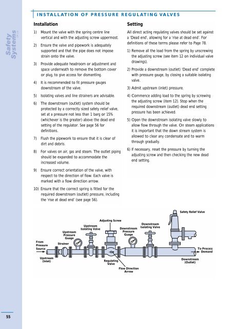
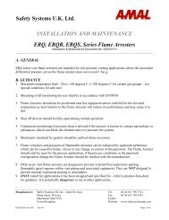
INSTALLATION OF PRESSURE REGULATING VALVESInstallation1) Mount the valve with the spring centre linevertical and with the adjusting screw uppermost.2) Ensure the valve and pipework is adequatelysupported and that the pipe does not imposestrain onto the valve.3) Provide adequate headroom or adjustment andspace underneath to remove the bottom coveror plug, to give access for dismantling.4) It is recommended to fit pressure gaugesdownstream of the valve.5) Isolating valves and line strainers are advisable.6) The downstream (outlet) system should beprotected by a correctly sized safety relief valve,set at a pressure not less than 1 barg or 15%(whichever is the greater) above the dead endsetting of the regulator. See page 56 fordefinitions.7) Flush the pipework to ensure that it is clear ofdirt and debris.8) For valves on air, gas and steam. The outlet pipingshould be expanded to accommodate theincreased volume.SettingAll direct acting regulating valves should be set againsta ‘Dead end’, allowing for a ‘rise at dead end’. Fordefinitions of these terms please refer to Page 78.1) Remove all the load from the spring by unscrewingthe adjusting screw (see item 12 on individual valvedrawings).2) Provide a downstream (outlet) ‘Dead end’ completewith pressure gauge, by closing a suitable isolatingvalve.3) Admit upstream (inlet) pressure.4) Commence adding load to the spring by screwingthe adjusting screw (item 12). Stop when therequired downstream (outlet) dead end settingpressure has been achieved.5) Open the downstream isolating valve slowly toallow flow through the valve. On steam applicationsit is important that the down stream system isallowed to clear any condensate and to warmthrough gradually.6) If necessary, reset the pressure by turning theadjusting screw and then checking the new deadend setting.9) Ensure correct orientation of the valve, withrespect to the direction of flow. Each valve ismarked with a flow direction arrow.10) Ensure that the correct spring is fitted for therequired downstream (outlet) pressure, includingthe ‘rise at dead end’ (see page 56).<strong>Safety</strong> Relief ValveFromPressureSourceUpstreamPressureGuageStrainerUpstreamIsolating ValveAdjusting ScrewDownstreamPressureGuageDownstreamIsolating ValveTo ProcessDemandUpstream(Inlet)RegulatingValveFlow DirectionArrowDownstream(Outlet)55


![ES139[IOM Fig 785 Marvac Emergency Relief Vent]](https://img.yumpu.com/43585698/1/190x245/es139iom-fig-785-marvac-emergency-relief-vent.jpg?quality=85)