Bailey Technical Catalogue - Safety Systems UK Ltd
Bailey Technical Catalogue - Safety Systems UK Ltd
Bailey Technical Catalogue - Safety Systems UK Ltd

Create successful ePaper yourself
Turn your PDF publications into a flip-book with our unique Google optimized e-Paper software.
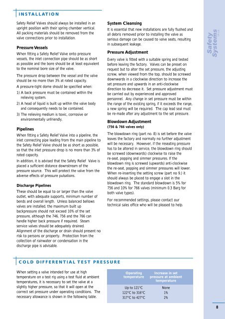
INSTALLATION<strong>Safety</strong> Relief Valves should always be installed in anupright position with their spring chamber vertical.All packing materials should be removed from thevalve connections prior to installation.Pressure VesselsWhen fitting a <strong>Safety</strong> Relief Valve onto pressurevessels, the inlet connection pipe should be as shortas possible and the bore should be at least equivalentto the nominal bore size of the valve.The pressure drop between the vessel and the valveshould be no more than 3% at rated capacity.A pressure-tight dome should be specified when:1) A back pressure must be contained within therelieving system.2) A head of liquid is built up within the valve bodyand consequently needs to be contained.3) The relieving medium is toxic, corrosive orenvironmentally unfriendly.PipelinesWhen fitting a <strong>Safety</strong> Relief Valve into a pipeline, theinlet connecting pipe leading from the main pipeline tothe <strong>Safety</strong> Relief Valve should be as short as possible,so that the inlet pressure drop is no more than 3% ofrated capacity.In addition, it is advised that the <strong>Safety</strong> Relief Valve isplaced a sufficient distance downstream of thepressure source. This will protect the valve from theadverse effects of pressure pulsations.Discharge PipelinesThese should be equal to or larger than the valveoutlet, with adequate supports, minimum number ofbends and overall length. Unless balanced bellowsvalves are installed, the maximum built upbackpressure should not exceed 10% of the setpressure, although the 746, 756 and the 766 canhandle higher back pressure if required. Steamservice valves should be adequately drained.Alignment of the discharge or drain should present norisk to persons or property. Protection from thecollection of rainwater or condensation in thedischarge pipe is advisable.System CleansingIt is essential that new installations are fully flushed andall debris removed prior to installing the valve asserious damage can be caused to valve seats, resultingin subsequent leakage.Pressure AdjustmentEvery valve is fitted with a suitable spring and testedbefore leaving the factory. Valves can be preset onrequest but to alter the set pressure, the adjustingscrew, when viewed from the top, should be screweddownwards in a clockwise direction to increase theset pressure and upwards in an anti-clockwisedirection to decrease it. Set pressure adjustment mustbe carried out by experienced and approvedpersonnel. Any change in set pressure must be withinthe range of the existing spring, if it exceeds the range,a new spring will be required. The cap lead seal mustbe re-made after any adjustment to the set pressure.Blowdown Adjustment(756 & 766 valves only)The blowdown ring (part no. 8) is set before the valveleaves the factory and normally no further adjustmentwill be necessary. However, if the reseating pressurehas to be altered in service, the blowdown ring shouldbe screwed (downwards) clockwise to raise there-seat, popping and simmer pressures. If theblowdown ring is screwed (upwards) anti-clockwisethe re-seat, popping and simmer pressures will lower.When re-inserting the setting screw (part no 9.) itshould always be placed to engage a slot in theblowdown ring. The standard blowdown is 5% for756 and 10% for 766 valves (minimum 0.3 Barg forboth valve types).For recommended settings, please contact ourtechnical sales office who will be pleased to help.COLD DIFFERENTIAL TEST PRESSUREWhen setting a valve intended for use at hightemperature on a test rig using a test fluid at ambienttemperatures, it is necessary to set the valve at aslightly higher pressure, so that it will open at thecorrect set pressure under operating conditions. Thenecessary allowance is shown in the following table.OperatingtemperatureIncrease in setpressure at ambienttemperatureUp to 121°CNone122°C to 316°C 1%317°C to 427°C 2%8


![ES139[IOM Fig 785 Marvac Emergency Relief Vent]](https://img.yumpu.com/43585698/1/190x245/es139iom-fig-785-marvac-emergency-relief-vent.jpg?quality=85)