Geckobot and Waalbot: Small-Scale Wall Climbing Robots - CiteSeerX
Geckobot and Waalbot: Small-Scale Wall Climbing Robots - CiteSeerX
Geckobot and Waalbot: Small-Scale Wall Climbing Robots - CiteSeerX
Create successful ePaper yourself
Turn your PDF publications into a flip-book with our unique Google optimized e-Paper software.
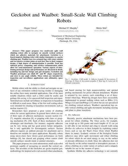
<strong>Geckobot</strong> <strong>and</strong> <strong>Waalbot</strong>: <strong>Small</strong>-<strong>Scale</strong> <strong>Wall</strong> <strong>Climbing</strong><strong>Robots</strong>Ozgur Unver †oUnver@<strong>and</strong>rew.cmu.eduMichael P. Murphy †mikemurphy@cmu.edu† Department of Mechanical EngineeringCarnegie Mellon UniversityPittsburgh, PA, USAMetin Sitti †sitti@cmu.eduAbstract— This paper proposes two small-scale agile wallclimbing robots able to navigate on smooth vertical surfaceswhich use adhesive materials for attachment. <strong>Geckobot</strong> is alizard-inspired climbing robot with similar kinematics to a geckoclimbing gait. <strong>Waalbot</strong> uses two actuated legs with rotary motion<strong>and</strong> two passive revolute joints at each foot. Due to their compactdesign, a high degree of miniaturization is possible. Each hasonboard power, computing, <strong>and</strong> wireless communication whichallow for semi-autonomous operation. Various aspects of functioningprototype design <strong>and</strong> performance are discussed in detail,including leg <strong>and</strong> feet design <strong>and</strong> gait dynamics. <strong>Geckobot</strong> <strong>and</strong><strong>Waalbot</strong> prototypes can climb 85 ◦ <strong>and</strong> 90 ◦ slopes respectively,<strong>and</strong> steer to any angle reliably. These robots are intended forinspection <strong>and</strong> surveillance applications <strong>and</strong>, ultimately, spacemissions.I. INTRODUCTIONMobile robots with the ability to climb <strong>and</strong> navigate on surfacesof any orientation without leaving residue or damagingthe surface have many potential applications. One of the mostnotable situations where such a robot could be useful, <strong>and</strong>perhaps life-saving, is for spacecraft hull inspection <strong>and</strong> repair.Terrestrial uses include surveillance or inspection in hazardousor difficult to reach areas. Many of the first wall scaling robotswere intended for cleaning in hazardous environments such asnuclear reactors [1].Researchers have proposed a great variety of climbingrobots for various applications. In general these robots use oneof three types of adhesion mechanism; vacuum suction [1]–[7], magnetic attraction [8], or gripping with claws or graspingmechanism [9], [10]. Each of these mechanisms has itsadvantages <strong>and</strong> drawbacks. For instance, magnetic adhesioncan be very strong <strong>and</strong> has good power failure mitigation,but is only applicable for ferromagnetic surfaces. Suctionadhesion requires an ambient pressure for attachment <strong>and</strong> istherefore not suitable for space applications. Recently, robotsusing micro-claws have shown good performance on brickbuldings [9], but clawed <strong>and</strong> grasping robots cannot climbsmooth surfaces smooth metal or painted structures.This paper proposes two semi-autonomous small-scale robotprototype capable of navigating on smooth flat vertical surfaces.The novelties of the <strong>Geckobot</strong> are gecko-inspired gait,methodology for inspired active tail assisted robust attachment,Fig. 1. <strong>Geckobot</strong> - CAD model. A: Adhesive footpads, B: Servomotors, C:Front legs, D: Waist, E: Servomotor propeller, F: Rear legs G: Active tail, H:Onboard components.tail based steering for high maneuverability, <strong>and</strong> optimalpeeling mechanisms for power efficient detachment. <strong>Waalbot</strong>is actuated by two motors, each controlling a set of threefootedwheel-legs. Wheel-leg designs have been successfullyimplemented in ground walking robots such as RHex [11],Whegs [12] <strong>and</strong> miniWhegs [13] robots but are not specializedfor climbing vertical surfaces. <strong>Waalbot</strong>’s specialized legs enablevertical climbing <strong>and</strong> agile movements including steering<strong>and</strong> plane to plane transitions.A. Dry AdhesionRecently, passive attachment mechanisms have been proposedfor robust climbing. The Tokay gecko, for example,can weigh up to 300 grams <strong>and</strong> reach lengths of 35 cm yetis still able to run inverted <strong>and</strong> cling to smooth walls usingfibrillar dry adhesives in their footpads by exploiting contactforces such as van der Waal’s Force (from which <strong>Waalbot</strong>draws its name). Synthetic versions of the biological Geckoadhesives may allow agile movements <strong>and</strong> robust climbingfor robots which do not need energy to stay on the surfaceor pressure differences to climb. Since dry adhesion does notrely heavily on the surface material or atmospheric pressure, itallows climbing on a wider variety of surfaces <strong>and</strong> is uniquelysuitable for use in the vacuum of space.Synthetic fibrillar dry adhesive technology is not currently
mature enough to be used for climbing robots, however <strong>Geckobot</strong><strong>and</strong> <strong>Waalbot</strong> are designed with the intention of eventuallyutilizing the technology. While efforts to develop the syntheticfibrillar dry adhesive continue, <strong>Waalbot</strong> uses a conventionaladhesive material (foam tape) which shares many performancecharacteristics with the envisioned dry adhesive material <strong>and</strong><strong>Geckobot</strong> utilizes dry adhesive patterned elastomers for attachment.Both the dry adhesive <strong>and</strong> the foam tape must bepressed to the surface with a preload force in order to providean adhesive force on detachment. This adhesive force increaseswith preload force up to a saturation point. The elastomers gaintheir adhesion performance by deforming into the microscalesurface features of any smooth surface <strong>and</strong> creating a largecontact area. Using these adhesives as substitutes until thefiber based dry adhesives have suitable performance for thisapplication allows testing <strong>and</strong> improvements to the robotdesign.A. <strong>Geckobot</strong> DesignII. ROBOT DESIGNSThis paper aims to design a gecko-inspired robot that canwalk, climb, <strong>and</strong> steer robustly <strong>and</strong> power efficiently as shownin Fig. 2. In order to achieve efficient wall climbing, therobot should be able to change orientation <strong>and</strong> move inall directions. The abilities to climb at any direction, avoidobstacles, steer <strong>and</strong> actively preload the tail are required.Peeling is a very crucial <strong>and</strong> challenging task for climbingrobots to improve their climbing ability <strong>and</strong> to minimizepower consumption. For autonomous performance, the sourceof energy, microprocessor, actuators <strong>and</strong> sensors have to beplaced on the robot.1) Walking on a Flat Surface: The robot body kinematicsis composed of a four-bar mechanism as shown in Fig. 3a.AB, BC, CD <strong>and</strong> ground are four linkages <strong>and</strong> the circleson the lines illustrate the joints. <strong>Geckobot</strong> sequentially pullstwo diagonally opposed feet up by using a motor on the fourbarmechanism, propelling itself forward. Then, the feet thatare aloft are attached to the ground <strong>and</strong> the opposite feet areFig. 2.<strong>Waalbot</strong>: Photograph of prototype climbing a 90 ◦ (vertical) surface.Fig. 3. (a) Four-bar mechanism of the <strong>Geckobot</strong> (left image), (b) The safetyregion of the <strong>Geckobot</strong> (right image).lifted for the next forward motion. The aim is to keep thecenter of gravity (CG) inside the safety region (SR) shown inFig. 3b, which is formed by the ground legs to keep the robotin balance. Firstly, the angle between waist <strong>and</strong> centerline, ϕ,has to be found to obtain the safety regiontan ϕ = (a + b)/L (1)sin ϕ = R/B (2)where a is the front, b is the rear waist width, R is the radiusof the foot, B is the vertical distance between safety regionlines, <strong>and</strong> L is the waist length. When the robot is stationary,as long as CG is in the SR robot does not fall aside when twofeet are aloft. However, when the robot moves, the CG movesa distance forward due to the rotation of the links, where θ isthe angle of the front foot rotation <strong>and</strong> s is the step size ofthe CG.s = a sin θ (3)Increasing the step size concludes decreasing the safety regionwith the amount of the CG shift, s. It is obvious that if θ,during walking, gets smaller <strong>and</strong> the foot diameter gets bigger,maintaining the balance becomes easier. In other words, thesafety region increases. The lengths a <strong>and</strong> b should be selectedvery carefully in order to make the CG lie intersection ofthe centerline that connects front <strong>and</strong> rear leg centers <strong>and</strong> theline that connects rear <strong>and</strong> front waist motors. The main aimbehind this idea is overlapping the CG point <strong>and</strong> SR center tomaximize the usage of the SR when the robot steps forward<strong>and</strong> backward. The safety region is calculated for varying legwidths <strong>and</strong> waist lengths. According to the calculations, thewaist length should be as small as possible, <strong>and</strong> the front <strong>and</strong>rear widths should be around 110 mm to maximize the safetyregion.2) <strong>Climbing</strong> Analysis: Unlike in ground walking, the projectionof the CG shifts backward during climbing. This shift,∆S, is related with the inclination, α, <strong>and</strong> CG height, h, ofthe robot as shown in Fig. 4.
Fig. 4.Projection of CG shift during slope-up climbing.Fig. 6.region.Optimization of the width of the <strong>Geckobot</strong> according to the safetyFig. 5.Safety region shift during side-walking.∆S = h tan α (4)However, the CG shifts sideways with the side slope, β,when <strong>Geckobot</strong> is walking across a slope. The CG height <strong>and</strong>dimensions of the robot directly affect the amount of side-shiftas shown in Fig. 5. Due to the shift, safety region decreaseswith the amount of loss (∆L). Side shift (S s ) can be expressedasS s = h tan β (5)<strong>and</strong> loss of the safety region can be expressed asL s = S s /tanϕ (6)In order to find the optimum width of the legs, climbing bothup <strong>and</strong> across a slope are analyzed. First, the waist length ofthe robot is taken arbitrarily <strong>and</strong> the leg width was taken as avariable between 50 mm, <strong>and</strong> 300 mm for both side-walking<strong>and</strong> slope-up climbing to obtain a 3-D safety region. Aftercombining these graphs into the same graph, an intersectionline is observed in Fig. 6. This line indicates the optimumwidth of the front <strong>and</strong> rear legs for the waist length chosenarbitrarily. If any other width is chosen, the performance ofthe side-walking might be increased but slope-up climbingperformance is diminished or vice versa. As a result, choosingthe intersection value gives us the optimum width duringwalking in any direction for the given waist length.A tail is one of the most important limbs for climbinganimals <strong>and</strong> robots. There are some benefits of having a tailwhile climbing, such as; holding onto supports, maintainingbalance <strong>and</strong> moving from one place to another, but the mainaim of having a tail is preloading. Pressing against the surfacewith a tail increases the normal force on the front toes leadingsecure climbing. If a maximum slope-up climbing angle isexceeded, the front toes detach from the surface due to themoment about the rear legs caused by the CG. A tail is addedto the system in order to transfer some load from the rear toesto the front toes increasing the maximum slope the robot canclimb. When <strong>Geckobot</strong> is climbing at 90 ◦ , at least 50 mNadhesion force is needed to keep the front toes on the surfacewithout a tail.However, with the aid of the tail, the adhesionforce needed can be decreased down to 25mN by preloadingthe tail 50 mN as shown in Fig. 7. Fig. 8 shows the forcesthat act on <strong>Geckobot</strong>’s toes <strong>and</strong> tail. F tx can be assumed zerosince the friction coefficient of the tail is very small <strong>and</strong> thepreload on the tail is not more than 60mN. F ty is the tailpreload <strong>and</strong> can be controlled by the rotation of the motor.Normal force under the rear toe becomesF ry = (mg cos αL 1 + mg sin αh − F ty(L 1 + L 2 + L 3 ))/(L 1 + L 2 ) (7)The normal force under the front toe turns out to beF ry = mg cos α − F ty − F ry (8)In Fig. 9, the force distribution during side walking is shown.F dx <strong>and</strong> F ux are the normal forces underneath the toes duringside-walking.F ux = (mg cos β − sin βh)/2a (9)F dx = mg cos β − F ux (10)<strong>Climbing</strong> is achieved if normal force on the pad is multipliedby coefficient of friction is bigger then the total force whichpulls the robot downwards parallel to the surface. If there aretwo components connected to each other <strong>and</strong> they have the
Fig. 7. Force distribution with tail during slope-up climbing while havingequal normal forces underneath the toes.Fig. 9.Force distributions during side-walking.Fig. 8.Force distributions during slope-up climbing.same coefficient of friction, the one that has lesser amountof normal force slides first down if pulling down forces areequal, <strong>and</strong> cause the other component to slide as well. Forthis reason, rear <strong>and</strong> front normal forces has to be as close aspossible for better climbing. As a conclusion, the tail motorshould push against the surface at just the right amount thatthe front <strong>and</strong> rear toes normal forces become equal at any time<strong>and</strong> any slope for stable climbing. This is because, although itis a four-bar mechanism, two actuators should be used to shareclimbing forces. In other words, the rear motor pushes <strong>and</strong> thefront motor pulls the robot up. Since their normal forces areequal <strong>and</strong> they are using the same pad materials, front <strong>and</strong>rear toes slip forces are going to be equal as well.First, the tail normal force versus climbing angle versusnormal force underneath the toes is drawn in 3-D mesh graph.The intersections of the front <strong>and</strong> rear preload surfaces givethe force on the tail to make the normal force of the toesequal. A cubic equation is fitted to the intersection curve y =1.5e − 005x 3 − 0.0057x 2 + 0.92x + 25. x is slope-up angle indegrees <strong>and</strong> y is the tail normal force in mN’s. The slope canbe detected using an accelerometer, <strong>and</strong> put into the equationdetermining the required normal force needed on the tail. Foraccurate <strong>and</strong> precise preloading, the position of the tail mustbe controlled. To accomplish this, a servomotor is chosen foractuation. If a tail is machined from a stiff material, very smallrotation of the servomotor will create a large preload force onthe tail, which is undesirable. Instead, a relatively compliantmaterial should be used to get good resolution out of the servorotation. When the servomotor presses on a complaint tail, itstarts to bend, but the preload force does not reach a very highlevel abruptly; instead, it is increased gradually, which givesbetter preload resolution.3) Steering: Steering is directly related to the system’sdegree of freedom (DOF). Since <strong>Geckobot</strong> is a four-barmechanism, it has one DOF. As explained in the previoussubsection, one more motor should be placed in the four-barmechanism for increasing climbing performance. However, notproper synchronization may result in a foot slip or inner torqueaccumulation that bends some part of the robot or increasesinstability. Synchronization is realized by using kinematicanalysis of the <strong>Geckobot</strong> as shown in Fig. 10.From kinematics, it is found out that when the front motorrotates with a specific degree, there is just one correct positionfor the rear motor due to the single DOF as shown in Fig. 11.be iθ3 + we iθ2 + ae iθ1 = |AD| (11)b cos θ 3 + a cos θ 1 = w − w cos θ 2 (12)b sin θ 3 + a sin θ 1 = a + b − wsinθ 2 (13)where, θ’s are the angle between the links as shown, w is thewaist length, <strong>and</strong> |AD| is the vectorial distance between pointA <strong>and</strong> D. The rear motor rotation angle is (180 − θ 3 + θ 2 )<strong>and</strong>, the front motor rotation angle is (θ 1 − θ 2 ) <strong>and</strong> both ofthem can be controlled.
Fig. 10.Kinematic diagram of the <strong>Geckobot</strong>.Fig. 12. CAD design of the peeling mechanism. A: Servomotor, B: Adhesivepads, C: Strings, D: Revolute joint, E: Spring, F: Cylindrical rodPolydimethyl siloxane (PDMS) elastomer surfaces are pulled.Then starting from the edge, the PDMS mold starts beingdeflected <strong>and</strong> peels off. There is a compression spring onthe shaft so when the pulling force exceeds the deflectionthreshold of the spring, foot starts to move up. Reattachmentto the ground is accomplished by rotating the servo arm toits original position <strong>and</strong> releasing the foot. Since compressionsprings are used, they push the whole mechanism back to itsoriginal position.Fig. 11.Kinematic angles of rear <strong>and</strong> front motor rotations.Steering is realized by controlling two servomotors onthe four-bar mechanism separately when the rear feet arealoft. While the robot is walking, the two motors rotate ina synchronized manner. When steering starts, its rear feet peeloff the ground <strong>and</strong> <strong>Geckobot</strong>’s tail presses harder against theground. Then, the front motor rotates the whole body to thedesired angle while the tail is sliding. At the same time, theback motor adjusts itself for the next step to the right anglewhile rear legs are aloft. The rotation of the rear servomotordoes not directly affect steering; however, right after steering,when the hind legs touch the ground, their position has to beplaced properly in relation to the position of the front legs.4) Peeling Mechanism: The peeling mechanism is verycrucial for climbing robots for power-efficient detachment asseen in geckos. For instance, to remove an ordinary piece oftape from an item, if pulled perpendicular to the surface fromthe center, a relatively high force would be required. However,instead of pulling the tape directly upwards, if it is peeledstarting from one side, it would come off very easily. Likethe tape example, the <strong>Geckobot</strong> has to peel during climbingin order to minimize the foot detaching force.The working mechanism of the peeling system is as follows.When the motor is energized, due to the rotation <strong>and</strong> displacementof the servo arm, all fishing lines <strong>and</strong> the adhesiveB. <strong>Waalbot</strong> Design1) <strong>Waalbot</strong> Mechanical Design: In order to create thepreload force required to bring the adhesive into intimatecontact with the surface, the robot has been designed tomaximize the pressing force when the adhesive pads comeinto contact with the climbing surface. This requirement guidesthe design of the legs <strong>and</strong> feet mechanisms. A gear motor’soutput shaft is connected to a triangular shaped leg, where eachpoint of the triangle holds a foot assembly on a revolute anklejoint (Fig. 13). This ankle joint assembly is spring loaded toalways return to the forward position (the robot cannot travelin reverse).Fig. 13. CAD model of the Tri-Foot design (left) <strong>and</strong> assembled prototypecomponents (right). Each foot pad has two degrees of freedom allowing forclimbing <strong>and</strong> turning.On the distal end of the foot assembly is another revolutejoint connecting a foot pad which holds the adhesive material.This final revolute joint enables steering capabilities (discussed
later in Section II-C). Only the outer annulus of the foot padis covered with adhesive (Fig. 2,13). This ensures that the footpad adheres flat to the surface while not sticking so much thatthe robot cannot peel the foot away.quasi-static dynamics <strong>and</strong> symmetric loading it is possible tofind a system of equations which describe the forces on therobot during the stepping transfer:∑Fy = 0 = F t + F Rn + F F n − W cos θ∑Fx = 0 = F Rx + F F x − W sin θFig. 14. Schematic side view of <strong>Waalbot</strong> climbing a vertical surface (top)<strong>and</strong> still photo frames from a video of the <strong>Waalbot</strong> prototype performing thesame actions (bottom).The principle of operation is as follows. During forwardtravel the two legs are synchronized <strong>and</strong> step in unison. Asthe motors turn, the tail of the robot presses against the surface<strong>and</strong> the triangular legs rotate forward. The two feet which areadhered to the surface (one on each side) support the weight ofthe robot (Fig. 14a). Soon the forward feet come into contactwith the surface (Fig. 14b). At this point there are 5 contactpoints with the surface; 2 feet on each side <strong>and</strong> the tail. Themotor torque provides an internal moment which presses thefront feet onto the surface while pulling the rear feet awayfrom the surface. When the rear foot normal force F Rn reachesa critical peeling value of F cr , the adhesive peels away fromthe surface <strong>and</strong> the robot steps forward.∑Mc = 0 = M + (F Rn − F F n )( d step2 )+ F t (L t ) + W sin θ(L yc − L ycg )−(F Rx + F F x )(L yc ) − W cos θ(L xcg )(14)where W is the weight, θ is the slope of the climbing surface,F t , F Rn , F F n are the normal forces at the tail, rear foot, <strong>and</strong>front foot respectively. F Rx <strong>and</strong> F F x are the shear forceson the rear <strong>and</strong> front feet respectively. d step is the distancebetween the centers of the rear <strong>and</strong> front feet, L yc is thedistance from the climbing surface to the center of the leg,<strong>and</strong> L ycg , L xcg are the distances from the center of gravity(C g ) to the surface <strong>and</strong> center of the leg respectively. L t isthe distance between the center of the leg <strong>and</strong> the tail-surfacecontact point.There are five unknown forces (F F n , F Rn , F F x , F Rx , F t )<strong>and</strong> only three equations, so in order to solve for the unknownssome assumptions must be made. Assuming F Rn = F cr willgive the forces just before the peel-off occurs, which is whenF F n is at a maximum. We also assume that the shear forceson the front <strong>and</strong> rear feet are equal (F F x = F Rx ). Lastly weassume that the torque just before peel-off is approximatelyequal to the the torque necessary to peel the rear feet <strong>and</strong>preload the front feet with an equal force(M = F cr·d step ).This assumption also guides the minimum motor torque requirementswhen designing the physical robot.Using these assumptions <strong>and</strong> (14) it is possible to examinethe effect of slope angle θ on the preload force F F n . Sincethis preload force is important for creating intimate contact<strong>and</strong> thus adhesion, it is of critical importance. The results ofthis modeling are used to guide the robot design to acheivehigh preload force.The adhesives used with the robot have very high shearresistance <strong>and</strong> therefore always detach because of a normalforce pulling the foot away from the surface. The minimumadhesion normal force required to keep the robot attached tothe wall during climbing can be found by examining the casewhen only one foot per side is attached <strong>and</strong> the C g is at itsfurthest distance from the surface. The quasi-static equationfor the case when the C g farthest from the wall (Fig. 15b)gives a maximum force which the adhesives must be able toprovide:Fig. 15. Free body diagrams showing the forces during a forward step (left)where the front foot is pressed against the surface <strong>and</strong> the rear foot is peeled,<strong>and</strong> in the configuration in which the robot experiences the highest peelingforce while climbing (right).Examining the free body diagram (Fig. 15a) <strong>and</strong> assumingF Rn = W L t(Lycg(max) sin θ − (L t − L xcg ) cos θ ) (15)If this force exceeds the magnitude of F cr then the robot willdetach from the surface. Therefore, this equation gives theminimum adhesive performance needed to climb. Of course,
ecause of the consequences of a fall, a safety factor is usedwhen choosing an adhesive <strong>and</strong> adhesive foot area.From (15) it is clear that in order to minimize the peelingforce on the adhesive pad during climbing, the length of thetail should be increased <strong>and</strong> also the center of gravity should bemoved close to the wall. Finally the weight of the robot shouldbe minimized. This may be accomplished through fabricatingthe robot from lighter materials or through miniaturization.Miniaturization is advantageous to this robot design becausemass is proportional to L 3 while the adhesion force is proportionalto area, thus L 2 . As the robot shrinks in size, theadhesion force will be reduced less than the gravitational force,so we will see an increase in the performance of the robot.Both equations suggest that the tail should be long toincrease preload force <strong>and</strong> to minimize the peeling force.However, it is important to note that the weight of the robotis also increased with the tail length, so there is a couplingbetween W <strong>and</strong> L t . Furthermore, a longer tail increasesthe amount of room necessary for turning, as the tail maysweep out <strong>and</strong> contact obstacles causing the robot to loseadhesion <strong>and</strong> fall, so a longer tail limits the ability to climbin small areas. Therefore, for maximum performance withoutcompromising agility the tail length is chosen to be the longestlength such that the tail remains fully within the turning circle(Fig. 16).A printed circuit board (PCB) acts as the chassis for therobot instead of using an additional body frame in order tokeep the mass low. The heaviest components of the system arethe leg assemblies (fabricated by rapid prototyping), motors,<strong>and</strong> batteries. In order to move the center of gravity as close aspossible to the surface <strong>and</strong> balanced around the motor axes, allof these parts are located around the motors, with the batteriesbeneath the PCB, almost touching the climbing surface.2) Electronics <strong>and</strong> Sensors: The robot is controlled by aPIC microcontroller (PIC16F737) <strong>and</strong> is able to perform preprogrammedactions such as climbing <strong>and</strong> turning without ainstructions from the user. Gait is controlled with feedbackfrom foot position sensors. Limit switches are triggered whenthe legs are aligned such that only one foot is contactingthe surface. This information is used to keep the robot’s gaitsynchronized by pausing one of the motors until the opposingmotor catches up, so that (14) applies. This is also importantfor safely putting the robot into steering mode.Infrared (IR) RC5 communication is used to teleoperatethe robot to climb straight, stop, <strong>and</strong> turn. Comm<strong>and</strong>s canbe sent for turning 180 ◦ , 90 ◦ , <strong>and</strong> in increments of 15 ◦ ineither direction. In the absence of user comm<strong>and</strong>s the robotwill perform a preprogrammed routine.Power is provided by two lithium ion polymer batterieswhich are placed in series beneath the body of the robot for 7.4volts. Power is regulated to 5V to drive the logic <strong>and</strong> sensorswhile unregulated power goes to the motors. The two motors(Sanyo 12GA-N4s) have a torque output of approximately400 mN·m each, which is enough to peel the rear feet fromthe surface.C. Agility1) Steering: When only one foot on a side is contacting thesurface, that foot can be used as a pivot point for the robotto turn around. By advancing the opposite motor, the robotrotates around the passive revolute joint in the pivoting foot.If the robot attempted to turn while two feet were attached ona side, the robot would shear itself off of the surface since thecenter of rotation would not be aligned with a joint. This canbe a catastrophic failure for a climbing robot, so foot positionsensors are used to prevent this occurrence.In steering mode, the robot takes discrete steps around thepivoting foot. The turning radius is less than the width ofthe robot so tight turns are possible (Fig. 16). The ability tomake tight turns is an important feature for climbing throughsmall passageways or for avoiding closely spaced obstacles.Path planning <strong>and</strong> odometry is simple for the Tri-Foot <strong>Waalbot</strong>because of the discrete nature of the movements, as well asthe non-slipping gait.Fig. 16. <strong>Waalbot</strong>’s small turning radius (R t) <strong>and</strong> turning circle radius (R tc)let it climb around obstacles <strong>and</strong> operate in narrow corridors with sharp bendsThe prototype <strong>Waalbot</strong> was designed to make discreteturning increments which change the heading by 15 ◦ per step.This angle is convenient as it allows for turns of 45 ◦ , 90 ◦ , 180 ◦as well as smaller adjustments.2) Plane Transitions: The robot’s unique jointed legs allowit to perform transitions between planes. For example, therobot can climb along a floor <strong>and</strong> transition to climb up avertical wall, then transition onto a wall or ceiling. The stepsof the transition process can be seen in Figure 17. As the robotapproaches a junction the forward foot makes contact with thenew plane (Fig. 17a) <strong>and</strong> the robot makes the planar transition(Fig. 17b,c).The Tri-Foot design gives the <strong>Waalbot</strong> the capability ofmaking planar transitions of various angles including 90 ◦ ,however the transitions are not fully robust. This is due tothe non-perpendicular angle at which the forward foot maycontact the new plane. Since the foot position is optimizedfor flat surface walking, when a new plane is encountered thefoot may not come into full contact immediately. In this casethe foot may not be preloaded correctly <strong>and</strong> adhesion cannot
Fig. 17. Schematic side view showing the steps in a 90 ◦ plane transition(top) <strong>and</strong> still photo frames of prototype <strong>Waalbot</strong> performing the transition(bottom).Fig. 18.PDMS preload vs adhesion graph.be guaranteed. In the worst case, the forward foot may l<strong>and</strong>in the junction, touching both planes <strong>and</strong> making very littlecontact, causing almost certain failure of adhesion. Therefore,depending on the relative angles of the approaching foot <strong>and</strong>the new plane, the robot may or may not successfully makethe transition.A. PROTOTYPEIII. PROTOTYPES1) Body Materials <strong>and</strong> Circuitry: The chassis of the <strong>Geckobot</strong>was built from Delrin R○ . The robot was equipped withseven servomotors (GWS Pico STD), four used for lifting therobotic legs, two for robot locomotion, <strong>and</strong> one for the activetail. The output torque of the servomotors is 70 Nmm when 5V is applied. PDMS is used as the dry adhesive elastomermaterial. PDMS adhesion pressure for various preloads isdisplayed in Fig. 18. On top of the PDMS layer, a very thinstainless steel is used for both fixing the fishing lines securely<strong>and</strong> giving the spring back behavior to the whole foot. Fishinglines pass between the PDMS layer <strong>and</strong> the stainless steelsheet. Fishing lines go out of the mold from the edges <strong>and</strong> areconnected to the servomotor with the aid of superglue. In thefour-bar mechanism, there is a pushpin on top of the PDMSlayer, half buried into the PDMS, as a revolute joint. All thefishing lines are passed through a same hole, when the motoris actuated, it is thereby guaranteed that all fishing lines ordeflected PDMS move the same distance.A compact on-board circuit is placed on the waist. This circuitexp<strong>and</strong>s the functionalities of the robot by adding modulessuch as wireless infrared (IR) communication, obstacle avoidance,serial communication, <strong>and</strong> in-circuit serial programming(ICSP) compatibility. The robot can be controlled via IR overRC5 protocol or serial communication over RS232. The IRproximity sensors allow the robot to avoid obstacles <strong>and</strong> steeraway from them. The motors are driven by a microcontroller,which also runs the main program. A three-axis accelerometeris used to sense orientation <strong>and</strong> control the active tail.Fig. 19.B. EXPERIMENTSPhoto of the <strong>Geckobot</strong> as parts displayed in Fig.1The overall weight of the robot is 100 grams includingthe electronic board. The total length is 190 mm withoutthe tail, width is 110 mm <strong>and</strong> tail length is 100 mm. Thedistance between the front legs <strong>and</strong> the CG is 100 mm asshown in Fig. 19. In these experiments, flat adhesives withoutpatterned surface are used on the feet. The speed of therobot is 5 cm/s during walking on the ground, but whenclimbing at higher angles, it decreases to 1 cm/s due tostability reasons. The robot is slowed due to attachment <strong>and</strong>detachment vibrations during climbing caused by the PDMSpad adhesives. <strong>Geckobot</strong> can climb up to 85 ◦ stably onPlexiglas surfaces as seen in Fig. 20. However, beyond thisangle stability diminishes abruptly. Since <strong>Geckobot</strong> is mainlydesigned for slope-up climbing instead of side-walking, itslength is longer than its width, which diminishes the robot’sside-walking performances. <strong>Geckobot</strong> cannot walk sidewayson a slope of more than 50 ◦ . Steering can be done effectively<strong>and</strong> very stably until 45 ◦ , as displayed in Fig. 21. The powerconsumption of the robot is around 1.4 Watts for 85 ◦ climbingmainly due to the servomotors.Experimental results of the tail preload force versus servomotorrotation angle, as demonstrated in Fig. 22, is exactlymatched with the theoretical calculations.
mechanism, the robot does not control its tail through feedbackfrom the system, potentially causing some problems duringclimbing. In addition, the <strong>Geckobot</strong> cannot peel very effectivelydue to the lack of molding techniques.If the force calculations are realized again considering thesame preload under the front <strong>and</strong> rear toesFig. 20. Photo snapshots of the <strong>Geckobot</strong> climbing on an acrylic flat surfacewith 85 degrees slope.Fig. 21.Photo snapshots of the <strong>Geckobot</strong> steering on a horizontal surface.C. DISCUSSIONSThe performance of the robot depends on the chosen adhesive<strong>and</strong> peeling mechanism. The presented research opens anew avenue in the design of high performance miniature wallclimbingrobots using active tail <strong>and</strong> peeling mechanism withdry adhesives. Here, flat PDMS elastomer is chosen as the dryadhesive. Although PDMS is a stable material, it is degraded<strong>and</strong> contaminated by the surface <strong>and</strong> the air within the time.That is, after sometime it looses its adhesive characteristics<strong>and</strong> some properties.Since an open-loop control system is used on the tailFig. 22.angle.Experimental tail normal force for varying servomotor rotationF fy = (mg cos α(L 3 + b) − sin αh)/(L 1 + L 2 + 2L 3 ) (16)F ux = mg(cos β − sin βh)/(a + b) (17)are derived for slope-up climbing <strong>and</strong> side-walking. It is seenthat, for climbing steeper angles the lengths of the robot shouldbe increased. However, tail length is much more important thanL 1 or L 2 . For side-walking, the robot should be as wide asit can be. For both cases, <strong>Geckobot</strong> should be designed verylight <strong>and</strong> very close to the ground.D. ExperimentsA prototype <strong>Waalbot</strong> was built according to the designaspects previously mentioned. This prototype has the followingspecifications:Prototype SpecificationsMass100 gLength13 cmHeight5 cmWidth (total)12.3 cmTurning Radius (R t ) 10 cmTurning Circle Radius (R tc ) 11.15 cmStep Length (d step ) 2.6 cmAdhesive Area (per foot) 1.5 cm 2Speed6 cm/sTurning Speed 37.5 ◦ /sVideos of the prototype performing various agility tasks canbe viewed at [14].The current <strong>Waalbot</strong> prototype was tested on a smooth clearacrylic climbing surface. It is capable of climbing any directionon a planes of various orientations. This includes climbing up,down, or across a vertical (90 ◦ ) wall, all at the speed of 6 cm/s.The maximum angle which the prototype was able to climbreliably was found to be 110 ◦ (20 ◦ past vertical).Power consumption was measured to be an average of2.42 watts with a maximum instantaneous power draw of2.66 watts while climbing vertically. This is very high for arobot of such small size. The pausing power consumption isapproximately 240 mW, <strong>and</strong> the average power consumptionrunning with the robot lifted off the ground measured as1.99 watts <strong>and</strong> a peak draw was 2.27 watts. This indicates thatthe work done to preload <strong>and</strong> peel the feet <strong>and</strong> to overcomegravity is around 400 mW <strong>and</strong> that the remainder of the powerconsumption is likely caused by frictional losses within themotors <strong>and</strong> drive train. Improving the drivetrain should reducepower consumption significantly.The prototype <strong>Waalbot</strong> is able to make left <strong>and</strong> right h<strong>and</strong>turns without falling from the climbing surface. Both small <strong>and</strong>
is required to improve performance due to increased area-tomassratio. Most of the electronic components are available insmaller, lighter surface mount-packages <strong>and</strong> along with superiorfabrication methods their use will lead to a reduction inoverall weight, allowing smaller, lighter actuators. Decreasingthe robot mass will result in higher payload capacity, allowingfor other sensors or tools <strong>and</strong> lower power consumption forlonger operation time.Fig. 23. Still frames from a video showing a <strong>Waalbot</strong> prototype turning whileclimbing on a vertical surface. The prototype turns 90 ◦ (line overlayed) insix steps (bottom a–f).large turning angles are routinely made. The prototype can beteleoperated to navigate around obstacles while climbing.The current prototype is capable of making transitions ofvarious angles, including 90 ◦ . We had not anticipated therobot successfully transitioning to a surface which was notexactly perpendicularly aligned with the robot’s path, but inmany tests, the prototype was indeed able to transfer when thesurface was misaligned by up to 10 ◦ .IV. CONCLUSIONTwo semi-autonomous tetherless robot prototypes were designed<strong>and</strong> fabricated which are able to climb on smoothsurfaces of various orientations. The robots can steer <strong>and</strong> turnwith a small turning radii to travel around tight corners. The<strong>Waalbot</strong> prototype is able to successfully perform plane toplane transitions of a wide variety of angles including 90 ◦junctions. IR communication is used to control the robots.<strong>Geckobot</strong> demonstrates effective climbing behavior on inclinedsurfaces up to 85 ◦ at a speed of 1 cm/s. The robotdesign is demonstrated to be efficient, reliable, <strong>and</strong> robust.Future versions will address many unresolved issues with thecurrent prototype including 90 ◦ surface climbing, obstacleavoidance, <strong>and</strong> autonomous navigation.<strong>Waalbot</strong> demonstrates climbing at slopes up to 110 ◦ ata speed of 6 cm/s. One of the major disadvantages of the<strong>Waalbot</strong> robot design is that there is very little redundancy incase of adhesion failure. At some times during operation thereare only two feet attached to the surface. Inverted walking hasnot been possible with the prototype due to the mass of therobot. Furthermore, the possibility of adhesion failure duringa transition if improper foot placement occurs is a dangerousflaw for a climbing robot. The adhesives used on the feet ofthe robot gather dust <strong>and</strong> other contaminants their performancedegrades quickly. Therefore, these adhesives are not suitablefor dirty outdoor environments, walking across indoor floors,or for long term tasks.Future work includes implementing the synthetic dry adhesivesin place of the conventional adhesives when thetechnology is mature. Further miniaturization of the robotsAcknowledgmentsThe authors acknowledge Ali Uneri <strong>and</strong> Alper Aydemir fortheir contributions to robot electronics <strong>and</strong> software, Will Tsofor his work on the <strong>Waalbot</strong> prototype design, fabrication, <strong>and</strong>testing, <strong>and</strong> all of the NanoRobotics Lab members for theirsupport.REFERENCES[1] W. Yan, L. Shuliang, X. Dianguo, Z. Yanzheng, S. Hao, <strong>and</strong> G. Xueshan,“Development <strong>and</strong> application of wall-climbing robots,” in IEEEInternational Conference on Robotics <strong>and</strong> Automation, 1999.[2] S. Hirose, A. Nagakubo, <strong>and</strong> R. Toyama, “Machine that can walk<strong>and</strong> climb on floors, walls <strong>and</strong> ceilings,” in ICAR. Fifth InternationalConference on Advanced Robotics, 1991.[3] S. Ryu, J. Park, S. Ryew, <strong>and</strong> H. Choi, “Self-contained wall-climbingrobot with closed link mechanism,” in International Conference onIntelligent <strong>Robots</strong> <strong>and</strong> Systems, 2001.[4] L. Briones, P. Bustamante, <strong>and</strong> M. Serna, “<strong>Wall</strong>-climbing robot forinspection in nuclear power plants,” in International Conference onRobotics <strong>and</strong> Automation, 1994.[5] R. Pack, J. Christopher, J.L., <strong>and</strong> K. Kawamura, “A rubbertuator-basedstructure-climbing inspection robot,” in International Conference onRobotics <strong>and</strong> Automation, 1997.[6] B. Luk, A. Collie, V. Piefort, <strong>and</strong> G. Virk, “Robug iii: a tele-operatedclimbing <strong>and</strong> walking robot,” in UKACC International Conference onControl, 1996.[7] T. Yano, T. Suwa, M. Murakami, <strong>and</strong> T. Yamamoto, “Development ofa semi self-contained wall climbing robot with scanning type suctioncups,” in International Conference on Intelligent <strong>Robots</strong> <strong>and</strong> Systems,1997.[8] J. Grieco, M. Prieto, M. Armada, <strong>and</strong> P. Gonzalez de Santos, “Asix-legged climbing robot for high payloads,” in IEEE InternationalConference on Control Applications, 1998.[9] S. Kim, A. T. Asbeck, M. R. Cutkosky, <strong>and</strong> W. R. Provancher, “Spinybotii:<strong>Climbing</strong> hard walls with compliant microspines,” in ICAR, 2004.[10] T. Bretl, S. Rock, <strong>and</strong> J.-C. Latombe, “Motion planning for a threelimbedclimbing robot in vertical natural terrain,” in IEEE InternationalConference on Robotics <strong>and</strong> Automation, 2003.[11] R. Altendorfer, N. Moore, H. Komsuoglu, M. Buehler, H. B. B. Jr.,D. McMordie, U. Saranli, R. Full, <strong>and</strong> D. E. Koditschek, “Rhex: Abiologically inspired hexapod runner.” Auton. <strong>Robots</strong>, vol. 11, no. 3, pp.207–213, 2001.[12] R. Quinn, D. Kingsley, J. Offi, <strong>and</strong> R. Ritzmann, “Improved mobilitythrough abstracted biological principles,” in IEEE Int. Conf. On Intelligent<strong>Robots</strong> <strong>and</strong> Systems (IROS’02), 2002.[13] J. M. Morrey, B. Lambrecht, A. D. Horchler, R. E. Ritzmann, <strong>and</strong>R. D. Quinn, “Highly mobile <strong>and</strong> robust small quadruped robots,” inIntl. Conference on Intelligent <strong>Robots</strong> <strong>and</strong> Systems, 2003.[14] [Online]. Available: http://www.me.cmu.edu/faculty1/sitti/nano/projects/waalbots/trileg.html


