Assembly and Disassembly of Magnetic Mobile Micro-Robots ...
Assembly and Disassembly of Magnetic Mobile Micro-Robots ...
Assembly and Disassembly of Magnetic Mobile Micro-Robots ...

You also want an ePaper? Increase the reach of your titles
YUMPU automatically turns print PDFs into web optimized ePapers that Google loves.
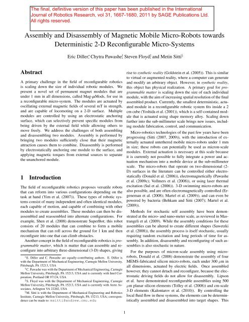
<strong>Assembly</strong> <strong>and</strong> <strong>Disassembly</strong> <strong>of</strong> <strong>Magnetic</strong> <strong>Mobile</strong> <strong>Micro</strong>-<strong>Robots</strong> towards<br />
Deterministic 2-D Reconfigurable <strong>Micro</strong>-Systems<br />
Eric Diller ∗ , Chytra Pawashe † , Steven Floyd ‡ , <strong>and</strong> Metin Sitti §<br />
Abstract<br />
A primary challenge in the field <strong>of</strong> reconfigurable robotics<br />
is scaling down the size <strong>of</strong> individual robotic modules. We<br />
present a novel set <strong>of</strong> permanent magnet modules that are<br />
under 1 mm in all dimensions, called Mag-µMods, for use in<br />
a reconfigurable micro-system. The modules are actuated by<br />
oscillating external magnetic fields <strong>of</strong> several mT in strength,<br />
<strong>and</strong> are capable <strong>of</strong> locomoting on a 2-D surface. Multiple<br />
modules are controlled by using an electrostatic anchoring<br />
surface, which can selectively prevent specific modules from<br />
being driven by the external field while allowing others to<br />
move freely. We address the challenges <strong>of</strong> both assembling<br />
<strong>and</strong> disassembling two modules. <strong>Assembly</strong> is performed by<br />
bringing two modules sufficiently close that their magnetic<br />
attraction causes them to combine. <strong>Disassembly</strong> is performed<br />
by electrostatically anchoring one module to the surface, <strong>and</strong><br />
applying magnetic torques from external sources to separate<br />
the unanchored module.<br />
1 Introduction<br />
The field <strong>of</strong> reconfigurable robotics proposes versatile robots<br />
that can reform into various configurations depending on the<br />
task at h<strong>and</strong> (Yim et al. (2007)). These types <strong>of</strong> robotic systems<br />
consist <strong>of</strong> many independent <strong>and</strong> <strong>of</strong>ten identical modules,<br />
each capable <strong>of</strong> motion, <strong>and</strong> capable <strong>of</strong> combining with other<br />
modules to create assemblies. These modules can then be disassembled<br />
<strong>and</strong> reassembled into alternate configurations. For<br />
example, Shen et al. (2008) demonstrate SuperBot; this robot<br />
consists <strong>of</strong> 20 modules that can combine to form a mobile<br />
mechanism that can roll across the ground for 1 km <strong>and</strong> then<br />
reconfigure into one that can climb obstacles.<br />
Another concept in the field <strong>of</strong> reconfigurable robotics is programmable<br />
matter, which is matter that can assemble <strong>and</strong> reconfigure<br />
into arbitrary three-dimensional (3-D) shapes, giving<br />
∗ E. Diller <strong>and</strong> C. Pawashe are equally-contributing authors. E. Diller is<br />
with the Department <strong>of</strong> Mechanical Engineering, Carnegie Mellon University,<br />
Pittsburgh, PA 15213, USA<br />
† C. Pawashe was with the Department <strong>of</strong> Mechanical Engineering, Carnegie<br />
Mellon University, Pittsburgh, PA 15213, USA <strong>and</strong> is currently with Intel Corporation,<br />
Portl<strong>and</strong> OR 97124, USA<br />
‡ S. Floyd was with the Department <strong>of</strong> Mechanical Engineering, Carnegie<br />
Mellon University, Pittsburgh, PA 15213, USA <strong>and</strong> is currently with Arete Associates,<br />
Arlington VA 22202, USA<br />
§ M. Sitti is with the Department <strong>of</strong> Mechanical Engineering <strong>and</strong> Robotics<br />
Institute, Carnegie Mellon University, Pittsburgh, PA 15213, USA; correspondence<br />
can be made to: msitti@<strong>and</strong>rew.cmu.edu<br />
rise to synthetic reality (Goldstein et al. (2005)). This is similar<br />
to virtual or augmented reality, where a computer can generate<br />
<strong>and</strong> modify an arbitrary object. However, in synthetic reality,<br />
this object has physical realization. A primary goal for programmable<br />
matter is scaling down the size <strong>of</strong> each individual<br />
module, with the aim <strong>of</strong> increasing spatial resolution <strong>of</strong> the final<br />
assembled product. Currently, the smallest deterministic, actuated<br />
module in a reconfigurable robotic system fits inside a 2<br />
cm cube (Yoshida et al. (2001)), which is a self-contained module<br />
that is actuated using shape memory alloy. Scaling down<br />
further into the sub-millimeter scale brings new issues, including<br />
module fabrication, control, <strong>and</strong> communication.<br />
<strong>Micro</strong>-robotics technologies <strong>of</strong> the past few years have been<br />
progressing (Sitti (2007, 2009)), with the introduction <strong>of</strong> externally<br />
actuated untethered mobile micro-robots under 1 mm<br />
in size; these robots can potentially be used as micron-scale<br />
modules. External actuation is necessary at this scale because<br />
it is currently not possible to fully integrate a power <strong>and</strong> actuation<br />
mechanism into a mobile device at the sub-millimeter<br />
scale. The micro-robots that operate on two-dimensional (2-<br />
D) surfaces in the literature can be controlled either electrostatically<br />
(Donald et al. (2006)), electromagnetically (Pawashe<br />
et al. (2009c); Vollmers et al. (2008)), or using laser thermal<br />
excitation (Sul et al. (2006)). 3-D swimming micro-robots are<br />
also possible, <strong>and</strong> are <strong>of</strong>ten electromagnetically controlled (Ergeneman<br />
et al. (2008); Martel et al. (2009)), <strong>and</strong> can even be<br />
powered by bacteria (Behkam <strong>and</strong> Sitti (2007); Martel et al.<br />
(2009)).<br />
Methods for stochastic self assembly have been demonstrated<br />
at the micro- <strong>and</strong> nano-meter scale, as reviewed in Mastrangeli<br />
et al. (2009). While the assembly conditions for these<br />
assemblies can be altered to create different shapes (Sawetzki<br />
et al. (2008)), the assembly process is itself stochastic, usually<br />
requiring r<strong>and</strong>om excitation <strong>and</strong> long periods <strong>of</strong> time for assembly.<br />
In addition, disassembly <strong>and</strong> reconfiguring <strong>of</strong> such assemblies<br />
is also stochastic in nature.<br />
For the purposes <strong>of</strong> micron-scale assembly using microrobots,<br />
Donald et al. (2008) demonstrate the assembly <strong>of</strong> four<br />
MEMS-fabricated silicon micro-robots, each under 300 µm in<br />
all dimensions, actuated by electric fields. Once assembled<br />
however, they cannot detach <strong>and</strong> reconfigure, because the electrostatic<br />
driving fields do not allow for disassembly. Lipson<br />
et al. have demonstrated reconfigurable assemblies using 500<br />
µm planar silicon elements (Tolley et al. (2008)) <strong>and</strong> cm-scale<br />
3-D elements (Kalontarov et al. (2010)). By controlling the<br />
local fluid flow in these systems, the elements can be deterministically<br />
assembled <strong>and</strong> disassembled into target shapes. This<br />
1
system relies on an active substrate to provide fluid flow <strong>and</strong><br />
control <strong>and</strong> so the assembled micron-scale elements have limited<br />
mobility. As a result, disassembling <strong>and</strong> reconfiguring fully<br />
deterministic mobile micron-scale modules is currently an unsolved<br />
problem.<br />
We first introduced a reconfigurable set <strong>of</strong> magnetic micromodules<br />
in Pawashe et al. (2009b), where the concept was described<br />
<strong>and</strong> initial experimental results were discussed. In this<br />
work, we present a more complete model <strong>of</strong> module assembly<br />
<strong>and</strong> disassembly processes with measurements <strong>of</strong> all relevant<br />
forces taken to compare with the models. A method to infer<br />
micro-scale properties <strong>of</strong> magnetic objects in-situ using magnetic<br />
fields is also proposed <strong>and</strong> used with the model. As a potential<br />
mobile reconfigurable system at the micrometer scale,<br />
the magnetic module system proposed in this paper is a step towards<br />
the creation <strong>of</strong> programmable reconfigurable assemblies.<br />
The contribution <strong>of</strong> this work is to identify <strong>and</strong> analyze the<br />
conditions for micron-scale module assembly <strong>and</strong> disassembly.<br />
We identify the effects <strong>of</strong> important physical parameters<br />
in these processes through approximate analytical models <strong>and</strong><br />
compare with empirical data. This information can be used for<br />
the design <strong>of</strong> more complex micro-scale reconfigurable systems<br />
using Mag-µMods or another platform.<br />
The paper is organized as follows: Section 2 introduces the<br />
reconfigurable micro-robot system concept used <strong>and</strong> Section 3<br />
describes the experimental setup used. Section 4 presents an<br />
analytical model <strong>of</strong> module assembly <strong>and</strong> disassembly <strong>and</strong> Section<br />
5 presents the experimental results. The paper is concluded<br />
in Section 6.<br />
2 Concept<br />
In this work, we propose using sub-millimeter scale untethered<br />
permanent magnet micro-robots (Mag-µBots) actuated by external<br />
magnetic fields (Pawashe et al. (2009c)) as components<br />
<strong>of</strong> magnetic micro-modules (Mag-µMods), for creating deterministic<br />
reconfigurable 2-D micro-assemblies; this implies that<br />
the Mag-µMods will be able to both assemble <strong>and</strong> disassemble.<br />
Strong permanent magnet modules will attract each other<br />
with large magnetic forces; therefore it is necessary to reduce<br />
this magnet force between modules to facilitate disassembly.<br />
This can be done by adding an outer shell to the Mag-µBot<br />
for the design <strong>of</strong> a module. The outer shell prevents two magnetic<br />
modules from coming into close contact, where magnetic<br />
forces will become restrictively high. However, they are still<br />
sufficiently close together to yield a mechanically stable assembly.<br />
This shell-based Mag-µMod is shown in Figure 1. Alternatively,<br />
a Mag-µBot can be magnetized to a magnetization value<br />
less than its saturation value, <strong>and</strong> then be used as a Mag-µMod;<br />
this is a shell-less Mag-µMod.<br />
Motion <strong>of</strong> multiple Mag-µMods is achieved by employing<br />
a surface divided into a grid <strong>of</strong> cells, where each cell on the<br />
surface contains an addressable electrostatic trap capable <strong>of</strong><br />
anchoring individual Mag-µMods to the surface by capacitive<br />
coupling; this prevents them from being actuated by the external<br />
magnetic fields. This approach is related to that found in<br />
the field <strong>of</strong> distributed manipulation (Bohringer (1999)), where<br />
Figure 1: (a) Conceptual schematic <strong>of</strong> a shell-based Mag-<br />
µMod. A permanent magnet core is surrounded by a magnetically<br />
inactive shell. (b) Photograph <strong>of</strong> a Mag-µMod on an electrostatic<br />
anchoring surface. A magnetic core with approximate<br />
dimensions 300 × 300 × 170 µm 3 is surrounded by a shell approximately<br />
600 × 600 × 270 µm 3 in outer dimensions.<br />
parts are manipulated in parallel using programmable force<br />
fields, but here the distributed cells provide only a retarding<br />
force while the actuation magnetic force is globally applied to<br />
all modules. Unanchored Mag-µMods can move on the surface<br />
due to the imposed magnetic fields, <strong>and</strong> move in parallel. This<br />
technique is identical to controlling multiple Mag-µBots, explained<br />
in detail in Pawashe et al. (2009a). Assembling two<br />
Mag-µMods is straightforward – by moving an unanchored<br />
Mag-µMod towards an anchored one, magnetic forces eventually<br />
dominate <strong>and</strong> cause the two Mag-µMods to self-assemble.<br />
For disassembly <strong>of</strong> two Mag-µMods to occur, the magnetic<br />
attraction between them must be overcome <strong>and</strong> the two separated.<br />
To do this, we use the electrostatic grid surface to anchor<br />
parts <strong>of</strong> assembled modules, <strong>and</strong> examine the effectiveness <strong>of</strong><br />
externally applied magnetic torques to disassemble unanchored<br />
modules from the assembly.<br />
Figure 2 shows the concept <strong>of</strong> multiple Mag-µMods assembling,<br />
disassembling, <strong>and</strong> reconfiguring into a different configuration.<br />
Because the Mag-µMods are magnetic, they can only<br />
assemble into configurations that are magnetically stable, implying<br />
that they form single closed flux loops.<br />
Four Mag-µMods are operated in Figure 3 to demonstrate<br />
that they can create configurations, <strong>and</strong> reconfigure into other<br />
morphologies. From this experiment, the modules initially assemble<br />
into a magnetically stable ‘T’ configuration, <strong>and</strong> then<br />
reconfigure into a line configuration that is capable <strong>of</strong> translation.<br />
3 Experimental Setup<br />
Mag-µMods are actuated by six independent electromagnetic<br />
coils (shown in in Figure 4), aligned to the faces <strong>of</strong> a cube<br />
approximately 8.2 cm on a side. Depending on the required<br />
magnetic fields <strong>and</strong> gradients, the coils can contain either an air<br />
core or an iron core. Properties <strong>of</strong> the electromagnetic system<br />
are provided in Table 1. Maximum fields or gradients correspond<br />
to using two coaxial coils on opposite sides driven at<br />
maximum current, <strong>and</strong> are measured using Hall effect sensors<br />
(Allegro 1321) placed in the micro-robot workspace. Gradients<br />
2
Figure 2: Schematic <strong>of</strong> five Mag-µMods operating on an electrostatic<br />
grid surface, where each cell can be individually activated<br />
to anchor-down individual Mag-µMods; unanchored<br />
Mag-µMods can be moved by the global magnetic field. (a)<br />
The five Mag-µMods are separate, <strong>and</strong> (b) assemble into a<br />
magnetically-stable line. In (c), the two outer Mag-µMods disassemble<br />
from the line, <strong>and</strong> (d) reconfigure into a magnetically<br />
stable ‘U’ shape.<br />
are determined by measuring the field difference between two<br />
points spaced 1 mm apart. Control <strong>of</strong> the currents driving the<br />
electromagnetic coils are performed by a PC with a data acquisition<br />
system at a control b<strong>and</strong>width <strong>of</strong> 10 kHz, <strong>and</strong> the coils<br />
are powered by linear electronic amplifiers.<br />
Actuation <strong>of</strong> each Mag-µMod is accomplished by using two<br />
or more electromagnetic coils. One or more horizontal coils are<br />
first enabled (coil D in Figure 4), causing the Mag-µMod to orient<br />
in the direction <strong>of</strong> the net magnetic field. Vertical clamping<br />
coils (coils C <strong>and</strong> F in Figure 4) are enabled <strong>and</strong> pulsed using a<br />
sawtooth waveform. This results in a non-uniform rocking motion<br />
<strong>of</strong> the Mag-µMod, which induces stick-slip motion across<br />
the surface. In general, the Mag-µBot’s velocity increases with<br />
pulsing frequency (typically from 1-200 Hz), <strong>and</strong> can exceed<br />
velocities <strong>of</strong> 50 mm/s in air. The Mag-µMod is also capable<br />
<strong>of</strong> operating in fluids <strong>of</strong> viscosities less than about 50 cSt, <strong>and</strong><br />
can operate on a variety <strong>of</strong> smooth <strong>and</strong> rough magnetically inactive<br />
surfaces, provided that the adhesion between the Mag-<br />
µMod <strong>and</strong> surface is low. Further explanation <strong>of</strong> this locomotion<br />
method is given in (Floyd et al. (2009); Pawashe et al.<br />
(2009a,c)) <strong>and</strong> demonstration movies can be found online 1 .<br />
3.1 Mag-µBot <strong>and</strong> Mag-µMod Fabrication<br />
Mag-µBots can be produced in a batch process using a molding<br />
technique, as described in Imbaby et al. (2008). The Mag-<br />
µBots used in this work are rectilinear <strong>and</strong> composed <strong>of</strong> a<br />
mixture <strong>of</strong> neodymium-iron-boron (NdFeB) particles (Magnequench<br />
MQP-15-7, refined in a ball mill to produce particles<br />
under 2 µm in size) suspended in a polyurethane (TC-<br />
892, BJB enterprises) matrix in a ratio <strong>of</strong> 1 part polyurethane<br />
to 4 parts NdFeB by weight. This material is referred to as<br />
1 NanoRobotics Laboratory<br />
http://nanolab.me.cmu.edu/projects/<strong>Magnetic</strong><strong>Micro</strong>Robot/<br />
Figure 3: Frames from a movie with four teleoperated Mag-<br />
µMods (species MR2) assembling into a reconfigurable structure<br />
(video available in Extension 1). Arrows indicate direction<br />
<strong>of</strong> magnetization. (a) Four Mag-µMods prepare for assembly.<br />
(b) Three modules are assembled, <strong>and</strong> the fourth approaches.<br />
(c) All four modules are assembled. (d) One module is broken<br />
free using the rotation method from Section 4.5. (e) The module<br />
reattaches in a new configuration. (f) The new assembly is<br />
mobile, <strong>and</strong> is shown moving to a new location.<br />
Property Value Units<br />
Number <strong>of</strong> turns 140 −<br />
Resistance 0.4 Ω<br />
Wire diameter 1.15 mm<br />
Coil length 3.2 cm<br />
Inner diameter 5.1 cm<br />
Distance to workspace 4.1 cm<br />
Max driving current 19 A<br />
Core length 10.1 cm<br />
Max field at workspace (air core) 12.0 mT<br />
Max gradient at workspace (air core) 0.44 T/m<br />
Max field at workspace (Fe core) 49 mT<br />
Max gradient at workspace (Fe core) 2.2 T/m<br />
Table 1: Properties <strong>of</strong> the electromagnets.<br />
<strong>Magnetic</strong>-Particle-Impregnated-Polyurethane (MPIP). The fabrication<br />
process is described in detail in Pawashe et al. (2009c).<br />
A shell-less Mag-µMod is a Mag-µBot created with a lower<br />
value <strong>of</strong> magnetization. To do this, the st<strong>and</strong>ard fabrication<br />
steps are used, but the final magnetization step is performed in<br />
a smaller magnetic field. A shell-based Mag-µMod has a nonmagnetic<br />
shell encasing a ferromagnetic core (the Mag-µBot).<br />
The shells are fabricated in a manner similar to the Mag-µBot,<br />
substituting aluminum powder for the magnetic powder to create<br />
aluminum-impregnated polyurethane (ALIP, in a ratio <strong>of</strong> 1<br />
part polyurethane to 1 part aluminum powder by weight), which<br />
is used to make the shells partially conductive; this increases<br />
the electrostatic anchoring force by increasing the total area <strong>of</strong><br />
conductive material.<br />
The shell-less Mag-µMods are refined in a laser-milling system<br />
due to their rough edges from molding, while the ALIP<br />
3
to generate high electric fields. Mag-µMods are placed on this<br />
surface <strong>and</strong> are operated in a low-viscosity silicone oil (Dow<br />
Corning 200 fluid, 20 cSt, with density <strong>of</strong> ρ oil ≈ 950 kg/m 3 )<br />
which supports the generation <strong>of</strong> the large electric fields required<br />
to anchor individual Mag-µMods. Anchoring occurs<br />
through a capacitive coupling force to the surface for conductive<br />
materials.<br />
4 Modeling<br />
Figure 4: Photograph <strong>of</strong> the electromagnetic coil setup. A:<br />
camera for visual feedback, B: microscope lens, C: top +z coil,<br />
D: one <strong>of</strong> four horizontal coils (the +x coil in particular), E:<br />
experiment workspace, <strong>and</strong> F: bottom -z coil. The -y coil is<br />
removed to allow viewing <strong>of</strong> the workspace.<br />
shells are used directly from the molding process.<br />
<strong>Assembly</strong> <strong>of</strong> the ferromagnetic core into a shell is performed<br />
manually using tweezers under an optical microscope, <strong>and</strong> the<br />
two components are held together by UV curable epoxy (Loctite<br />
3761). Figure 1(b) displays an assembled Mag-µMod. In<br />
the presence <strong>of</strong> the global magnetic fields, these modules move<br />
similarly to individual Mag-µBots without shells, exhibiting<br />
stick-slip motion across the working surface, however at lower<br />
velocities <strong>of</strong> about 0.5 mm/s.<br />
Three shell-less <strong>and</strong> three shell-based species <strong>of</strong> Mag-µMods<br />
are used in this study, with properties listed in Table 2. <strong>Magnetic</strong><br />
moments (m) were measured in a vibrating sample magnetometer<br />
(ADE Technologies Inc.), <strong>and</strong> dimensions were measured<br />
in an optical microscope with an error <strong>of</strong> ±10 µm. Module<br />
shell <strong>and</strong> core dimensions were chosen to cover a range <strong>of</strong><br />
sizes which allow for the creation <strong>of</strong> stable assemblies which<br />
can be disassembled with the field strengths available, with an<br />
upper size limit <strong>of</strong> 1.0 mm. The buoyant weight (W b ) <strong>of</strong> each<br />
module are empirically determined by finding the minimum z-<br />
directed magnetic field gradient ( dBec,z<br />
dz<br />
in Table 2) required to<br />
levitate it in silicone oil (as used in the experiments), <strong>and</strong> using<br />
(2), giving W b = m dBec,z<br />
dz<br />
. In this measurement, only the<br />
+z coil is utilized, causing the Mag-µMod to orient <strong>and</strong> move<br />
in the +z-direction. dBec,z<br />
dz<br />
has an estimated error <strong>of</strong> 25 mT/m<br />
<strong>and</strong> W b has up to ±14% error.<br />
3.2 Electrostatic Grid Surface Fabrication<br />
The electrostatic grid surface, described in Pawashe et al.<br />
(2009a), is used to enable the control <strong>of</strong> multiple Mag-µBots or<br />
Mag-µMods. It consists <strong>of</strong> an array <strong>of</strong> independently addressable<br />
pads, each pad containing a set <strong>of</strong> interdigitated electrodes<br />
In modeling the operation <strong>of</strong> a Mag-µMod, we are interested<br />
in its interactions with the externally applied magnetic fields,<br />
electrostatic fields from the surface, magnetic fields from other<br />
Mag-µMods, <strong>and</strong> surface effects such as adhesion <strong>and</strong> friction<br />
at the micro-scale. Figure 5 displays a typical static configuration<br />
<strong>of</strong> two assembled Mag-µMods, M1 <strong>and</strong> M2. Nomenclature<br />
for the forces <strong>and</strong> torques acting on modules are given in Table<br />
3.<br />
Term<br />
m<br />
M<br />
V<br />
⃗B i<br />
⃗B ec<br />
⃗F ec<br />
⃗T ec<br />
⃗F i<br />
⃗T i<br />
F s,f<br />
F s,e<br />
F s,i<br />
F e<br />
N<br />
N i<br />
F f<br />
F f,i<br />
W b<br />
Definition<br />
Module magnetic moment<br />
Module magnetization per volume<br />
Module magnetic core volume<br />
Module magnetic field<br />
Externally applied magnetic field<br />
Externally applied magnetic force<br />
Externally applied magnetic torque<br />
<strong>Magnetic</strong> force between modules<br />
<strong>Magnetic</strong> torque between modules<br />
Module to surface adhesive force for area contact<br />
Module to surface adhesive force for line contact<br />
Adhesive force between modules<br />
Electrostatic anchoring force to the surface<br />
Reaction normal force from the surface<br />
Reaction normal force between modules<br />
Friction force from the surface<br />
Friction force between modules<br />
Buoyant weight<br />
Table 3: Select nomenclature.<br />
4.1 <strong>Magnetic</strong> Influences<br />
Each magnetized Mag-µMod creates a magnetic field <strong>of</strong><br />
⃗B i (x, y, z), <strong>and</strong> the six external electromagnets create a magnetic<br />
field <strong>of</strong> ⃗ B ec (x, y, z). <strong>Magnetic</strong> torques exerted on Mag-<br />
µMods are proportional to the magnetic field strength, <strong>and</strong> act<br />
to bring their internal magnetizations into alignment with the<br />
field. The magnetic forces exerted on Mag-µMods are proportional<br />
to the spatial gradient <strong>of</strong> the magnetic field, <strong>and</strong> act to<br />
move them to a local maximum. The magnetic torques <strong>and</strong><br />
4
dB ec,z<br />
dz<br />
Species Core Size (µm 3 ) Shell Size (µm 3 ) m<br />
W b<br />
L×W×H L×W×H (mEMU) (mT/m) (µN)<br />
MR1 225 × 250 × 180 848 × 837 × 271 0.83 1340 1.10 ± 0.02<br />
MR2 215 × 225 × 172 541 × 565 × 249 1.0 946 0.95 ± 0.03<br />
MR3 110 × 115 × 97 318 × 328 × 232 0.20 1200 0.23 ± 0.01<br />
MR4 500 × 530 × 170 – 2.6 187 0.48 ± 0.06<br />
MR5 413 × 421 × 177 – 2.0 213 0.42 ± 0.05<br />
MR6 298 × 298 × 200 – 0.87 224 0.19 ± 0.01<br />
Table 2: Measured properties <strong>of</strong> the Mag-µMods. Measurements <strong>of</strong> dBec,z<br />
dz<br />
are used to calculate the buoyant weight W b . Modules<br />
are magnetized along the length dimension.<br />
forces are determined using the general relations, integrating<br />
over volume <strong>of</strong> the magnet (Cheng (1992)):<br />
∫<br />
⃗T m = ⃗M × B(x, ⃗ y, z) dV (1)<br />
∫<br />
⃗F m =<br />
V<br />
V<br />
(⃗m • ⃗ ∇) ⃗ B(x, y, z) dV (2)<br />
where ⃗ T m <strong>and</strong> ⃗ F m are the general magnetic torques <strong>and</strong> forces<br />
the Mag-µMod experiences, respectively, <strong>and</strong> ⃗ M is the magnetization<br />
vector <strong>of</strong> the Mag-µMod. ⃗ B(x, y, z) is the total magnetic<br />
field at (x, y, z), which is the summation <strong>of</strong> ⃗ B ec (x, y, z)<br />
<strong>and</strong> all ⃗ B i (x, y, z) from other Mag-µMods in the workspace.<br />
Far from the field source ⃗ B becomes relatively constant over<br />
the volume <strong>and</strong> these equations can be simplified to the single<br />
dipole approximation.<br />
To approximate the forces <strong>and</strong> torques Mag-µMods exert on<br />
each other, the structure <strong>of</strong> the magnetic field generated by each<br />
Mag-µMod is required. To estimate these fields, Mag-µMods<br />
are modeled as distributed magnetic dipoles, with the total contribution<br />
to the field determined numerically. The field generated<br />
by these distributed magnetic dipoles is (Cheng (1992)):<br />
⃗B( M, ⃗ ⃗r) = µ ∫<br />
0<br />
4π V<br />
1<br />
[<br />
|⃗r| 5 3⃗r( M ⃗ · ⃗r) − M ⃗ ]<br />
(⃗r · ⃗r) dV (3)<br />
where µ 0 = 4π × 10 −7 [H/m] is the permeability <strong>of</strong> free space<br />
<strong>and</strong> ⃗r is the vector from the dipole to the point <strong>of</strong> interest. In<br />
practice, the magnetic volume is discretized into a finite number<br />
<strong>of</strong> magnetic dipoles for ease <strong>of</strong> calculation.<br />
4.2 Surface Adhesion<br />
Forces between the surface <strong>and</strong> a Mag-µMod can include capillary,<br />
electrostatic, <strong>and</strong> van der Waals effects (Israelachvili<br />
(1992)), <strong>and</strong> are here lumped together into one force, the magnitude<br />
<strong>of</strong> which can depend on whether the Mag-µMod is contacting<br />
the surface on an edge (F s,e ) or is lying flat (F s,f ). This<br />
force depends on the material properties <strong>of</strong> the Mag-µMod, surface,<br />
<strong>and</strong> environment.<br />
For edge-contact, F s,e is estimated using a method depicted<br />
in Figure 6, where an applied magnetic field gradient in the z-<br />
direction<br />
(<br />
∂Bec,z<br />
∂z<br />
)<br />
is increased until the Mag-µMod lifts away<br />
from the surface. The magnetic force (F ec,z ) due to this gradient<br />
must overcome W b <strong>and</strong> F s,e . A uniform x-directed field is<br />
also generated to orient the Mag-µMod at an angle θ with the<br />
surface, ensuring edge contact. F s,e can be calculated as:<br />
F s,e = F ec,z − W b = [m 1 sin(θ)] ∂B ec,z<br />
− W b (4)<br />
∂z<br />
( )<br />
θ = tan −1 Bz<br />
(5)<br />
B x<br />
Equation (5) assumes that ⃗m 1 is parallel to ⃗ B ec , which is appropriate<br />
since the imposed magnetic torques that support this<br />
relation dominate other torques. Additionally, N vanishes right<br />
before the Mag-µMod leaves the surface, <strong>and</strong> is not present in<br />
the relations.<br />
For flat-contact adhesion, F s,f is estimated using a method<br />
depicted in Figure 7, where a known uniform B ec,z is applied<br />
to rotate the Mag-µMod away from the surface, causing it to<br />
pivot about P r . The applied magnetic torque must overcome<br />
the torque exerted onto the Mag-µMod by F s,f <strong>and</strong> W b , which<br />
are taken to act at the centroid <strong>of</strong> the Mag-µMod.<br />
Considering the static condition <strong>of</strong> the Mag-µMod right before<br />
it rotates away from the surface, F s,f can be calculated<br />
as:<br />
F s,f = 2m 1B ec,z<br />
L m<br />
− W b (6)<br />
which assumes that ⃗m 1 is orthogonal to ⃗ B ec .<br />
4.3 Sliding Friction<br />
The friction coefficient (µ) between surfaces at the micro-scale<br />
can vary from bulk macro-scale values. Thus it is necessary to<br />
infer µ using micro-scale objects to obtain an accurate in-situ<br />
value. To estimate µ between a Mag-µMod <strong>and</strong> a surface, we<br />
apply known forces onto the Mag-µMod that cause it to slide<br />
on its edge with the surface, as shown in Figure 8. A magnetic<br />
field in the x <strong>and</strong> z-directions is applied to ensure the Mag-<br />
µMod is on its edge. The x-directed magnetic field gradient,<br />
∂B ec,x<br />
∂x<br />
, is then increased until the Mag-µMod slips, indicating<br />
that the static friction force has been overcome. Using a basic<br />
Coulomb friction relation, µ is estimated:<br />
5
+z coil<br />
F f = µN = µ (W b + F s,e − F ec,z ) (7)<br />
z<br />
F ec -W b<br />
µ =<br />
F ec,x<br />
W b + F s,e − F ec,z<br />
(8)<br />
F ec,x = [m 1 cos(θ)] ∂B x<br />
∂x<br />
where ⃗m 1 is assumed to be parallel to ⃗ B.<br />
(9)<br />
-x coil<br />
y<br />
x<br />
M1<br />
m 1<br />
θ<br />
L/2<br />
Surface<br />
+x coil<br />
T ec<br />
F s,e -N<br />
4.4 <strong>Assembly</strong> <strong>of</strong> <strong>Magnetic</strong> <strong>Micro</strong>-Modules<br />
As two Mag-µMods with aligned magnetizations approach<br />
each other, their magnetic attraction increases due to the approximate<br />
r −3 dependence <strong>of</strong> their fields, from (3). At a critical<br />
separation distance, d x,c , the attractive forces overcome other<br />
forces, causing the modules to self-assemble. This assembly<br />
process is illustrated in Figure 9.<br />
To determine d x,c , we assume that Tm ⃗ dominates other<br />
torques, <strong>and</strong> take M1’s moment vector to align with B. ⃗ This<br />
implies:<br />
( )<br />
θ = − tan −1 Bz<br />
B x<br />
(10)<br />
⃗m 2 = m 2 [cos(θ)⃗a x − sin(θ)⃗a z ] (11)<br />
where ⃗a x <strong>and</strong> ⃗a z are unit vectors in the x <strong>and</strong> z-directions, respectively.<br />
When M2 is about to assemble with M1, summing the forces<br />
in the x <strong>and</strong> z-directions from Figure 9 gives:<br />
N = F s,e + W b − F ec,z − F i,z (12)<br />
F i,x = F f − F ec,x (13)<br />
⃗F i can be determined using B ⃗ i with (2), <strong>and</strong> using ⃗m<br />
from (11). Bi ⃗ from M1 can be determined using (3) with<br />
⃗m = ⃗m 1 = m 1 ⃗a x . Fec ⃗ can be determined using (2) with the<br />
known applied B ⃗ ec , <strong>and</strong> ⃗m 2 from (11). ⃗r in these computations<br />
L m<br />
W b<br />
T ec +T i<br />
F ec + F i<br />
M1<br />
M2<br />
H m<br />
m 1 N i -F s,i m 2<br />
F f Surface<br />
F id,g + N - F s,f<br />
Figure 5: Side view schematic <strong>of</strong> two Mag-µMods assembled<br />
together. M1 is anchored to the surface, <strong>and</strong> forces <strong>and</strong> torques<br />
acting upon it are displayed. Relevant geometry <strong>and</strong> coordinates<br />
used in equations are shown.<br />
y<br />
z<br />
x<br />
Figure 6: Free body diagram for estimating the edge-contact<br />
surface force, F s,e . The +z, −x, <strong>and</strong> +x coils create a magnetic<br />
field that orients the Mag-µMod at θ with the surface. A<br />
gradient in the +z-direction is increased until the Mag-µMod<br />
lifts <strong>of</strong>f the surface. No gradient in the x-direction is generated,<br />
<strong>and</strong> thus there is no x-directed force. Arrows on coils<br />
Mag-µMod<br />
indicate<br />
direction <strong>of</strong> magnetic field generated by the coil.<br />
T ec<br />
M1<br />
Surface<br />
F s,f + W b<br />
+z coil<br />
-z coil<br />
m 1<br />
L m /2<br />
Figure 7: Free body diagram for estimating the flat-contact surface<br />
force. A uniform field is generated using the +z <strong>and</strong> -z<br />
coils. This field is increased until the Mag-µMod rotates about<br />
P r , its pivot point with the surface. Arrows on coils indicate<br />
direction <strong>of</strong> magnetic field generated by the coil.<br />
is calculated using the geometries in Figure 9 as:<br />
( )<br />
φ = tan −1 Hm<br />
L m<br />
(14)<br />
d z = 1 √<br />
H<br />
2<br />
2 m + L 2 m sin(θ + φ) − H m<br />
2<br />
(15)<br />
⃗r = −d x,c ⃗a x + d z ⃗a z (16)<br />
where d z is the center-to-center distance from M1 to M2 in the<br />
z-direction.<br />
Subsequently, d x,c can be numerically solved using (10)-<br />
(16). Surface forces <strong>and</strong> friction coefficients are determined<br />
using the methods in Section 4.2.<br />
A layered assembly <strong>of</strong> two modules can be achieved by tilting<br />
the approaching module M2 up on its back edge so that it<br />
mounts the top <strong>of</strong> the anchored module as shown in Fig. 11(a).<br />
P r<br />
N<br />
y<br />
z<br />
x<br />
6
y<br />
z<br />
T ec<br />
x<br />
F f<br />
F s,e -N<br />
+z coil<br />
M1<br />
-z coil<br />
m 1<br />
W b<br />
F ec<br />
θ<br />
Surface<br />
+x coil<br />
y<br />
z<br />
x<br />
W b<br />
F ec + F i<br />
L m<br />
M1 m 1<br />
H<br />
F<br />
M2<br />
s,i<br />
m<br />
N m 2<br />
i P c1<br />
F f,i<br />
T ec +T i<br />
F s,f<br />
F f<br />
m2<br />
P r1<br />
N<br />
M2'<br />
P r2<br />
m 2<br />
M2"<br />
Surface<br />
Figure 10: Schematic <strong>of</strong> two initially assembled modules, M1<br />
<strong>and</strong> M2, throughout the rotational disassembly process. Module<br />
M1 is electrostatically anchored to the surface, while M2 is<br />
in the process <strong>of</strong> being disassembled to position M2 ′ , <strong>and</strong> then<br />
to M2 ′′ .<br />
Figure 8: Free body diagram depicting the method for estimating<br />
the friction coefficient. The +z <strong>and</strong> -z coils create a uniform<br />
+z-directed field. The +x coil creates a +x-directed field<br />
<strong>and</strong> gradient. The x-directed coil may use an iron core to increase<br />
the x-directed magnetic field gradient, which causes the<br />
Mag-µMod to slide on the surface.<br />
T ec +T i<br />
Surface<br />
M2<br />
W b<br />
θ<br />
m 2<br />
F f<br />
N-F s,e<br />
d x<br />
F ec + F i<br />
Figure 9: Schematic <strong>of</strong> two Mag-µMods, M1 <strong>and</strong> M2, assembling.<br />
M1 is anchored to the surface, <strong>and</strong> when M2 approaches<br />
the critical distance, d x = d x,c , the magnetic attractive force<br />
will pull M2 into contact with M1.<br />
4.5 <strong>Disassembly</strong> <strong>of</strong> Planar <strong>Magnetic</strong> <strong>Micro</strong>-<br />
Modules<br />
One set <strong>of</strong> methods to disassemble two modules that are assembled<br />
in the planar configuration from Figure 5 takes advantage<br />
<strong>of</strong> magnetic torques, which are generally stronger than magnetic<br />
forces at the micro-scale (Abbott et al. (2009)). One such<br />
rotational disassembly method is shown in Figure 10. The procedure<br />
for this disassembly method is:<br />
L m<br />
m 1<br />
1. The assembly <strong>of</strong> M1 <strong>and</strong> M2 is translated into a position<br />
where the electrostatic anchoring surface completely anchors<br />
M1 but leaves M2 free.<br />
2. Using z-directed magnetic fields, M2 is rotated until it<br />
aligns with the z-axis, indicated by position M2 ′ .<br />
3. M2 is then further rotated until its magnetization opposes<br />
M1’s, inducing a repulsive force; this position is M2 ′′ .<br />
4. M2 simply walks away from M1 using a stick-slip translation<br />
procedure, which is now possible due to the repulsion<br />
between the two modules.<br />
φ<br />
y<br />
z<br />
M1<br />
d i<br />
x<br />
H m<br />
The required external magnetic fields to rotationally disassemble<br />
M2 from M1 can be determined by analyzing the forces<br />
M2 experiences. We are primarily interested in the most difficult<br />
disassembly step, which is when M2 is initially assembled<br />
with M1 <strong>and</strong> moves to M2 ′ . The static case is taken where M2<br />
begins to rotate about the contact point P r1 ; this implies that N<br />
acts at P r1 , <strong>and</strong> the normal force between M2 <strong>and</strong> M1, N i , acts<br />
at P c1 . To determine the required ⃗ B ec to perform this step, we<br />
sum the in-plane torques on M2 about P r1 <strong>and</strong> use (1), giving:<br />
T ec,y = −T i,y − (F i,x + F ec,x − F s,i ) H m<br />
2<br />
− (F i,z + F ec,z − W b − F s,f − 2F f,i ) L m<br />
2<br />
(17)<br />
B ec,z = T ec,y<br />
m 2<br />
(18)<br />
Since uniform z-directed magnetic fields are used in this procedure,<br />
⃗ F ec = 0.<br />
⃗F i can be determined using (2) with (3), where ⃗r = L m ⃗a x ,<br />
⃗m = m 1 ⃗a x for determining ⃗ B i , <strong>and</strong> ⃗m = m 2 ⃗a x for determining<br />
⃗ F i . Similarly, ⃗ T i can be determined using (1) with (3). F s,i<br />
<strong>and</strong> F s,f are determined with the methods in Section 4.2. F f,i<br />
is the friction force between M2 <strong>and</strong> M1 before M2 slips on<br />
M1. F f,i <strong>and</strong> N i can be determined using Figure 10 by summing<br />
the forces in the x-direction, <strong>and</strong> taking F f = 0 since M2<br />
is supported by M1 in the x-direction:<br />
N i = F s,i + F i,x (19)<br />
F f,i = µ i N i (20)<br />
Thus with (17)-(20), the minimum ⃗ B ec can be found that<br />
accomplishes the Mag-µMod rotation described in Figure 10.<br />
4.6 <strong>Disassembly</strong> <strong>of</strong> Layered <strong>Magnetic</strong> <strong>Micro</strong>-<br />
Modules<br />
Mag-µMods can assemble to form a layered configuration that<br />
retains a significant total magnetization, as shown in Figure<br />
11(a). From Figure 11(b), the procedure for disassembly is:<br />
1. The combined modules M1 <strong>and</strong> M2 are translated into a<br />
position where the electrostatic anchoring surface completely<br />
anchors M1. M2 is far enough from the surface<br />
7
y<br />
z<br />
H m<br />
x<br />
M1<br />
T ec +T i<br />
m 1<br />
L m<br />
F s,i<br />
W b<br />
F ec + F i<br />
m 2<br />
M2<br />
P c1<br />
c o<br />
Surface<br />
(a) Two Mag-µMods, M1 <strong>and</strong> M2, are initially assembled in a layered configuration.<br />
y<br />
z<br />
x<br />
L m<br />
m 1<br />
T ec +T i<br />
W b<br />
M1<br />
m 2<br />
H m<br />
F s,i<br />
M2'<br />
F ec + F i<br />
P r2<br />
m 2<br />
M2''<br />
Surface<br />
(b) M2 disassembles from M1 using a rotational disassembly process. M1 is<br />
electrostatically anchored to the surface. M2 moves into position M2 ′ about<br />
P c1 , <strong>and</strong> then into M2 ′′ about P r2 , at which point it can walk away.<br />
Figure 11: Schematic <strong>of</strong> two Mag-µMods disassembling from<br />
a layered configuration.<br />
that it will not be affected by the electric fields from the<br />
electrostatic anchoring surface.<br />
2. M2 is rotated about P c1 in Figure 11(a) until it aligns with<br />
the z-axis by using z-directed magnetic fields. The resulting<br />
configuration is shown as M2 ′ in Figure 11(b).<br />
3. M2 is then further rotated using -x-directed magnetic<br />
fields until its magnetization points in the -x-direction.<br />
The resulting configuration is shown as M2 ′′ in Figure<br />
11(b).<br />
4. M1 <strong>and</strong> M2 are in a repulsive configuration with each<br />
other, <strong>and</strong> M2 can simply walk away from M1 using a<br />
stick-slip translation procedure.<br />
The required external magnetic fields to rotationally disassemble<br />
M2 from M1 can be determined by analyzing the forces<br />
M2 experiences. From experimental observation, the most difficult<br />
step in this disassembly procedure is rotating M2 into M2 ′<br />
from Figure 11(b), <strong>and</strong> thus will be the focus <strong>of</strong> analysis. In<br />
Figure 11(a), M2 is initially assembled with M1; the static case<br />
is then taken where M2 just begins to rotate about the contact<br />
point P c1 . Because P c1 will not necessarily be located directly<br />
below the center <strong>of</strong> mass <strong>of</strong> M2, the weight <strong>of</strong> M2 will induce<br />
an additional torque about P c1 . To determine the required B ec,z<br />
to perform this step, the in-plane torques on M2 are summed<br />
about P c1 , <strong>and</strong> (1) is used, giving:<br />
T ec,y = −T i,y − (F i,x + F ec,x ) H m<br />
2<br />
(21)<br />
− (F i,z + F ec,z − W b ) (L m − c o ) + F s,i<br />
L m − c o<br />
2<br />
B ec,z = T ec,y<br />
m 2<br />
(22)<br />
where c o is the overhang <strong>of</strong> M2 from M1.<br />
⃗F i can be determined using (2) with (3), where ⃗r =<br />
( 1<br />
2 L m + c o<br />
)<br />
⃗ax +H m ⃗a z , <strong>and</strong> θ = 0. Similarly, ⃗ T i can be determined<br />
using (1) with (3). F s,i is determined experimentally using<br />
the methods in Section 4.2. In reality, these adhesion forces<br />
represents a pressure across the surface <strong>of</strong> M2; in analysis, it is<br />
taken to be a single force acting upon the centroid <strong>of</strong> the contact<br />
area between M1 <strong>and</strong> M2. The overhang distance, c o , can<br />
be estimated by finding the c o that minimizes the magnetostatic<br />
energy between the two modules. This can be performed by<br />
a numerical iterative process by finding the c o that minimizes<br />
F i,x on M2 using (2) <strong>and</strong> (3).<br />
Thus with (21)-(22), ⃗ Bec can be solved to accomplish the<br />
Mag-µMod disassembly described in Figure 11.<br />
5 Experimental Results <strong>and</strong> Discussion<br />
In the surface force <strong>and</strong> friction experiments, Mag-µMods are<br />
operated on a glass or polyurethane (PU) surface; the glass<br />
surface simulates a glass-based electrostatic anchoring surface,<br />
while the PU surface replicates a module’s surface. Electromagnetic<br />
fields <strong>and</strong> gradients are measured post-experiment by<br />
placing a Hall sensor at the location <strong>of</strong> the Mag-µMod <strong>and</strong><br />
recreating the currents through the coils used in the experiments.<br />
In the assembly <strong>and</strong> disassembly experiments, a simplified<br />
environment is used where one Mag-µMod is glued onto a glass<br />
surface to simulate electrostatic anchoring. In the demonstration<br />
experiments, a glass-based electrostatic anchoring surface<br />
with four anchoring pads in a 2 × 2 configuration is utilized.<br />
Motion is achieved by pulsing the electromagnetic coils from<br />
1-10 Hz using a sawtooth waveform. All experiments are performed<br />
in a silicone oil fluid environment.<br />
In all experiments, at least three trials are performed to determine<br />
repeatability <strong>and</strong> error. In all data sets, errors are considered<br />
from all known sources. All measurements reported were<br />
taken in a single day. Module surface properties such as friction<br />
<strong>and</strong> adhesion have been observed to change over the course<br />
<strong>of</strong> several weeks, but over a single day the properties are very<br />
consistent. This was verified by repeating experiments over the<br />
course <strong>of</strong> day <strong>and</strong> demonstrating a low degree <strong>of</strong> variability as<br />
shown in the data presented here. The longer-term changes in<br />
properties (observed to change by a relative error up to 200%)<br />
are possibly due to differences in temperature <strong>and</strong> humidity,<br />
absorption <strong>of</strong> liquid into the module bodies over time as well<br />
as oxidation <strong>of</strong> the magentic material resulting in a decreased<br />
magnetic moment. These effects can possibly be stabilized by<br />
storing the modules in their operation environments or by using<br />
more stable materials.<br />
8
1200<br />
1000<br />
Flat Adhesion<br />
Edge Adhesion<br />
Module Weight<br />
1200<br />
1000<br />
Flat Adhesion PU<br />
Edge Adhesion PU<br />
Module Weight<br />
800<br />
800<br />
Force (nN)<br />
600<br />
400<br />
Force (nN)<br />
600<br />
400<br />
200<br />
200<br />
0<br />
0<br />
−200<br />
MR1 MR2 MR3 MR4 MR5 MR6<br />
Module Species #<br />
−200<br />
MR1 MR2 MR3 MR4 MR5 MR6<br />
Module Species #<br />
Figure 12: The adhesive force between the Mag-µMods <strong>and</strong> a<br />
glass surface for the flat case (F s,f ) <strong>and</strong> the edge case (F s,e ).<br />
The four flat adhesion plots correspond to experiments performed<br />
on each <strong>of</strong> the four edges <strong>of</strong> each module. Module<br />
weight is also shown for comparison.<br />
Figure 13: The adhesive force between the Mag-µMods <strong>and</strong> a<br />
polyurethane surface for the flat case (F s,f ) <strong>and</strong> the edge case<br />
(F s,e ). The four flat adhesion plots correspond to experiments<br />
performed on each <strong>of</strong> the four edges <strong>of</strong> each module. Module<br />
weight is also shown for comparison.<br />
To use (3) in computation, each permanent magnetic body<br />
was taken as at least 4 3 dipoles, evenly distributed throughout<br />
the magnetic body. This was found to be less than 3% different<br />
from a solution with 5 3 dipoles. A larger number <strong>of</strong> dipoles will<br />
lead to a more accurate solution, but with higher computational<br />
expense.<br />
5.1 Surface Adhesion<br />
Using the experiment <strong>and</strong> models described in Section 4.2, the<br />
surface forces are determined between the Mag-µMod <strong>and</strong> a<br />
surface. Figure 12 shows the forces for a glass surface, <strong>and</strong><br />
Figure 13 shows the forces for a polyurethane surface. The<br />
weight <strong>of</strong> each Mag-µMod is displayed for comparison. Data<br />
used to compute these forces are available in Extension 3.<br />
In general, F s,e , determined with the method from Figure 6,<br />
is similar among all the Mag-µMod species, indicating that the<br />
difference in size among the modules does not affect the edgebased<br />
adhesion. Since adhesion is normally area dependent, it<br />
would be expected that a Mag-µMod with a larger edge would<br />
experience larger adhesive forces. However, it is likely that the<br />
modules are contacting the surface with their asperities due to<br />
large surface roughnesses, implying that the effective area <strong>of</strong><br />
contact is similar for all species.<br />
F s,f , determined with the method from Figure 7, can vary<br />
among Mag-µMods <strong>and</strong> is seen to have large experimental error.<br />
In this experiment, modules were rotated from each <strong>of</strong> the<br />
four possible edges, as during assembly or disassembly. This<br />
is shown in the figures by the four flat adhesion values plotted<br />
for each module species. Due to the nature <strong>of</strong> the experiment,<br />
the assumption that the adhesive force is acting upon the module’s<br />
COM may be incorrect. At one extreme, the asperities<br />
will be at opposite ends (separated by a distance L), <strong>and</strong> at the<br />
other extreme we assume a rounded bottom face such that the<br />
Mag-µMod would rotate so that the effective asperity separation<br />
would be zero. Therefore, ignoring other sources <strong>of</strong> error,<br />
the experiment could give values <strong>of</strong> flat adhesion from zero to<br />
double the actual L/2 average value. This wide spread <strong>of</strong> adhesion<br />
values is seen between the edges, especially for species<br />
MR2. When these data are used later as surface parameters in<br />
the analytical model, the average value <strong>and</strong> st<strong>and</strong>ard deviation<br />
from all four edges is used because it is difficult to determine<br />
which edge the module is rotating about. Comparing measured<br />
adhesion values between a glass surface <strong>and</strong> polyurethane surface,<br />
there is not significant difference.<br />
Some measurements result in slightly negative adhesion, or<br />
repulsion from the surface. The methods described in Section<br />
4.2 should not be able to give a negative value as any repulsion<br />
from the surface will not assist the Mag-µMod in rotating away<br />
from the surface in the flat-adhesion measurement method, or<br />
lift away from the surface in the edge-adhesion measurement<br />
method. Therefore, the few negative adhesion values obtained<br />
are considered erroneous.<br />
5.2 Sliding Friction<br />
Using the experiment <strong>and</strong> models described in Section 4.3, the<br />
friction coefficient is determined between the Mag-µMod <strong>and</strong><br />
a surface. Figure 14 shows the friction coefficient for a glass<br />
surface <strong>and</strong> polyurethane surface. Data used to compute these<br />
forces are available in Extension 3.<br />
For the friction coefficients on a glass surface, there is not<br />
a significant difference among the Mag-µMods; the shell-less<br />
modules experience on average a slightly higher friction coefficient.<br />
On a polyurethane surface, it is clear that the shellless<br />
Mag-µMods, which contact the surface with MPIP, are exhibiting<br />
higher friction coefficients than the shell-based Mag-<br />
µMods, which contact the surface with its ALIP shell. This<br />
9
2<br />
on glass<br />
on polyurethane<br />
Friction Coefficient<br />
1.5<br />
1<br />
0.5<br />
Figure 15: Frames from a movie showing two Mag-µMods<br />
(species MR2), M1 (anchored) <strong>and</strong> M2 (unanchored), assembling<br />
into a planar configuration (video available in Extension<br />
2). (a)-(b) M2 walks towards M1, <strong>and</strong> both modules have<br />
aligned magnetizations. (c) The two modules assemble due to<br />
magnetic attraction forces. Direction <strong>of</strong> magnetization is shown<br />
on each module.<br />
0<br />
MR1 MR2 MR3 MR4 MR5 MR6<br />
Module Species #<br />
2000<br />
1800<br />
Figure 14: The friction coefficient between the Mag-µMod <strong>and</strong><br />
a surface <strong>of</strong> glass <strong>and</strong> polyurethane.<br />
difference would indicate that the polyurethane that binds the<br />
metallic powders in ALIP <strong>and</strong> MPIP is not the exposed material.<br />
In fabrication, the shell-less Mag-µMods are refined in a<br />
laser-milling system, which can potentially expose the embedded<br />
NdFeB particles. The ALIP shells are not laser-refined <strong>and</strong><br />
are taken directly from the molding process. This difference<br />
can lead to different sets <strong>of</strong> materials being in contact with the<br />
working surface, leading to different frictional properties.<br />
5.3 Planar <strong>Assembly</strong> <strong>of</strong> <strong>Magnetic</strong> <strong>Micro</strong>-<br />
Modules<br />
Mag-µMod assembly is performed using the method described<br />
in Section 4.4, <strong>and</strong> a demonstration <strong>of</strong> assembly is shown in<br />
Figure 15. To compare with the model in Section 4.4, each<br />
species <strong>of</strong> Mag-µMod is walked slowly towards a fixed Mag-<br />
µMod <strong>of</strong> the same species <strong>and</strong> is assembled. The jump-into distance<br />
is estimated from experimental video. A sawtooth waveform<br />
is used for walking actuation, with a maximum x <strong>and</strong> z-<br />
directed field <strong>of</strong> 1.3 mT. The x-directed magnetic field gradient<br />
is zero, since the +x <strong>and</strong> -x coils are used in equal opposition.<br />
The z-directed magnetic field gradient is 58 mT/m if the +z-coil<br />
is used for pulsing, or -58 mT/m if the -z-coil is used for pulsing.<br />
In model computations, F s,e is taken as the edge-adhesion<br />
data from Figure 12, <strong>and</strong> µ is taken from data in Figure 14.<br />
Using the assembly model described in Section 4.4, along<br />
with surface forces <strong>and</strong> friction coefficients from Figures 12–<br />
14, the estimated d x,c is determined, <strong>and</strong> presented in Figure<br />
16 for the case with a positive z-directed gradient, <strong>and</strong> in Figure<br />
17 for the case with a negative z-directed gradient. Because it<br />
is unclear what angle θ the Mag-µMod is in experiment right<br />
before assembly occurs, two bounding cases are simulated: (1)<br />
θ = 0 takes the case that the z-directed magnetic fields <strong>and</strong><br />
gradients are zero, <strong>and</strong> (2) θ = θ max takes the case that the<br />
z-directed magnetic fields <strong>and</strong> gradients are at their maximum<br />
d x,c<br />
(µm)<br />
1600<br />
1400<br />
1200<br />
1000<br />
800<br />
600<br />
400<br />
200<br />
0<br />
Experiment<br />
Simulation, θ = 0<br />
Simulation, θ = θ max<br />
MR1 MR2 MR3 MR4 MR5 MR6<br />
Module Species #<br />
Figure 16: Experiment <strong>and</strong> simulation <strong>of</strong> the Mag-µMods assembling<br />
(with jump-into distance d x,c ), with a magnetic field<br />
gradient in the +z-direction. In each experiment, one Mag-<br />
µMod is fixed on the surface, <strong>and</strong> the other walks towards it.<br />
Simulated data have error bars as empirically determined surface<br />
forces <strong>and</strong> friction are used in computation.<br />
magnitude. From these results, the experimental d x,c in Figure<br />
16 is bounded by the two simulated bounds <strong>and</strong> error ranges for<br />
all Mag-µMod species except for MR1.<br />
Generally, d x,c is slightly larger for the case <strong>of</strong> a positive z-<br />
directed gradient in the experiments. In this condition, a magnetic<br />
force acts to lift the Mag-µMod away from the surface,<br />
which in effect reduces N with the surface, <strong>and</strong> thus reduces<br />
F f . A smaller friction force will provide less resistance to the<br />
magnetic attraction between two modules, <strong>and</strong> thus will jumpinto<br />
contact at a longer range. In the simulations, d x,c is only<br />
slightly larger for the case <strong>of</strong> the positive z-directed gradient<br />
waveform in the θ = θ max case (the θ = 0 case is identical in<br />
both simulation sets). The dependence <strong>of</strong> d x,c on θ can be significant,<br />
<strong>and</strong> the θ that occurs during jump-into contact can be<br />
different depending on whether a positive or negative z-directed<br />
gradient was used.<br />
10
2000<br />
1800<br />
1600<br />
Experiment<br />
Simulation, θ = 0<br />
Simulation, θ = θ max<br />
1400<br />
d x,c<br />
(µm)<br />
1200<br />
1000<br />
800<br />
600<br />
400<br />
200<br />
0<br />
MR1 MR2 MR3 MR4 MR5 MR6<br />
Module Species #<br />
Figure 18: Frames from a movie showing two Mag-µMods<br />
(species MR2), M1 (anchored) <strong>and</strong> M2 (unanchored), disassembling<br />
from a planar configuration (video avaiable in Extension<br />
2). (a) Initial configuration. (b) M2 rotates into a vertical<br />
orientation with magnetization out <strong>of</strong> the page, <strong>and</strong> rotates further<br />
in (c) until it is in a repulsive orientation with M1. Direction<br />
<strong>of</strong> magnetization is shown on each module.<br />
Figure 17: Experiment <strong>and</strong> simulation <strong>of</strong> the Mag-µMods assembling<br />
(with jump-into distance d x,c ), with a magnetic field<br />
gradient in the -z-direction. In each experiment, one Mag-<br />
µMod is fixed on the surface, <strong>and</strong> the other walks towards it.<br />
Simulated data have error bars as empirically determined surface<br />
forces <strong>and</strong> friction are used in computation.<br />
Another issue that is not considered in simulation is how F f<br />
depends on the Mag-µMod’s state. In the measurements, F f<br />
comes from a static friction assumption; however, because the<br />
module translates using a stick-slip behavior, its point <strong>of</strong> contact<br />
with the surface can be sliding when jump-into contact occurs,<br />
<strong>and</strong> result in a smaller friction force, as kinetic friction is<br />
generally smaller than static friction. This effect could explain<br />
the disparity in the experiment <strong>and</strong> simulation for the case <strong>of</strong><br />
MR1 in Figure 16.<br />
5.4 <strong>Disassembly</strong> <strong>of</strong> Planar <strong>Magnetic</strong> <strong>Micro</strong>-<br />
Modules<br />
For Mag-µMods that are assembled in a planar fashion (as<br />
in Figure 5), disassembly is performed using the method described<br />
in Section 4.5. A demonstration <strong>of</strong> this disassembly is<br />
shown in Figure 18. In the experiments, each species <strong>of</strong> Mag-<br />
µMod disassembles from another <strong>of</strong> the same species from an<br />
initially assembled state. The magnetic fields that begin to disassemble<br />
the Mag-µMods are recorded, <strong>and</strong> are compared to<br />
the estimates from the models in Section 4.5. These comparisons<br />
are shown in Figure 19, which also includes a simulation<br />
that considers µ i = 0, since it is unclear in the experiments<br />
whether the modules are in intimate contact. In model computations,<br />
F s,f is taken as the flat-adhesion data from Figure 12,<br />
F s,i is taken as the flat-adhesion data from Figure 13, <strong>and</strong> µ i is<br />
taken from data in Figure 14.<br />
From these results, it is not clear whether the friction between<br />
modules is important or not, <strong>and</strong> can be dependent on<br />
specific micro-modules. For MR3-MR5, the experimental results<br />
lie in the bounding cases within error, however the simulations<br />
underestimate the required B ec,z for MR1 <strong>and</strong> MR2,<br />
<strong>and</strong> overestimate the required B ec,z for MR6. Large simulation<br />
deviations are seen for MR4-MR6, which result from the large<br />
errors in the measurement in friction, shown in Figure 14.<br />
One possible explanation for an underestimation in the required<br />
B ec,z is that the contact between two modules has interlocking<br />
asperities. This would cause a significantly higher<br />
required torque in order to rotate the disassembling module,<br />
as mechanical interlocking will be significantly stronger than<br />
the sliding friction model from the simulation. The shell-based<br />
modules (MR1-MR3) exhibit this behavior, which can have<br />
rough surfaces on their outside faces. The shell-less modules<br />
(MR4-MR6), which are refined in a laser after fabrication, may<br />
have smoother faces, reducing the chance <strong>of</strong> interlocking between<br />
modules. For MR4-MR6, the simulation bounds or overestimates<br />
the required B ec,z , which may support a sliding friction<br />
assumption between the faces (although <strong>of</strong> uncertain N i ,<br />
thus an uncertain F f,i ).<br />
It is unclear as to why MR6 is overestimated in both bounds<br />
from the simulation, which implies that there is more than just<br />
the inter-surface contact that can add error in these results.<br />
Other sources <strong>of</strong> error can include the possibility that the modules<br />
may not be perfectly aligned, <strong>and</strong> that a module’s magnetization<br />
is not perfectly parallel with its length. Also because <strong>of</strong><br />
the fabrication process, the density <strong>of</strong> the modules may not be<br />
uniform, <strong>and</strong> thus not have uniform magnetization. In particular,<br />
it is believed that there are air bubbles embedded inside the<br />
modules, which may not be uniformly distributed. As a result,<br />
the effective magnetic ‘centers’ <strong>of</strong> a Mag-µMod may not be its<br />
geometric center, <strong>and</strong> lead to skewed results for disassembly.<br />
5.5 <strong>Disassembly</strong> <strong>of</strong> Layered <strong>Magnetic</strong> <strong>Micro</strong>-<br />
Modules<br />
For Mag-µMods that are assembled in a layered fashion (as<br />
in Figure 11(a)), disassembly is performed using the method<br />
described in Section 4.6. A demonstration <strong>of</strong> disassembly is<br />
shown in Figure 20.<br />
In the experiments, each species <strong>of</strong> Mag-µMod disassembles<br />
from another <strong>of</strong> the same species from an initially assembled<br />
state. Only MR1-MR3 are able to achieve the initially<br />
assembled layered state; MR4-MR6 are not stable in this configuration<br />
without the polyurethane shell to support their can-<br />
11
70<br />
60<br />
Experiment<br />
Simulation<br />
Simulation µ i<br />
=0<br />
7<br />
6<br />
Experiment<br />
Simulation<br />
50<br />
5<br />
B ec,z<br />
(mT)<br />
40<br />
30<br />
B ec,z<br />
(mT)<br />
4<br />
3<br />
20<br />
2<br />
10<br />
1<br />
0<br />
MR1 MR2 MR3 MR4 MR5 MR6<br />
Module Species #<br />
0<br />
MR1 MR2 MR3<br />
Module Species #<br />
Figure 19: Experiment <strong>and</strong> simulation <strong>of</strong> the Mag-µMods disassembling<br />
from a planar assembly using a rotational disassembly<br />
method. In each experiment, one Mag-µMod is fixed on the<br />
surface, <strong>and</strong> the other is initially combined with it. Simulated<br />
data have error bars as empirically determined surface forces<br />
<strong>and</strong> friction are used in computation.<br />
tilevered weight. Therefore, only MR1-MR3 are analyzed. The<br />
magnetic fields that begin to disassemble the Mag-µMods are<br />
recorded, <strong>and</strong> are compared to the estimates from the models<br />
in Section 4.6. In model computations, F s,i is taken as the flatadhesion<br />
data from Figure 13, with the assumption <strong>of</strong> asperity<br />
contact, to account for the disparity in module area during the<br />
adhesion measurement, compared to the disassembly case. The<br />
results from the experiment <strong>and</strong> model are shown in Figure 21.<br />
From these results, the predicted B ec,z match the experimentally<br />
determined B ec,z well for MR1 <strong>and</strong> MR2. The model<br />
slightly underestimates the required field for MR3. This underestimation<br />
could be due due to the small deviation in MR3<br />
measurements in the experiment, compared to MR1 or MR2.<br />
One possibility for this result is that insufficient disassembly<br />
attempts were performed, <strong>and</strong> a very particular case was being<br />
Figure 20: Frames from a movie showing two Mag-µMods<br />
(species MR2), M1 (anchored) <strong>and</strong> M2 (unanchored), disassembling<br />
from a layered configuration (video available in Extension<br />
2). (a) Initial configuration. (b) M2 rotates into a vertical<br />
orientation with magnetization into the page, <strong>and</strong> rotates<br />
further in (c) until it is in a repulsive orientation with M1. Direction<br />
<strong>of</strong> magnetization is shown on each module.<br />
Figure 21: Experiment <strong>and</strong> simulation <strong>of</strong> the Mag-µMods disassembling<br />
from a layered assembly using a rotational disassembly<br />
method. In each experiment, one Mag-µMod is fixed<br />
on the surface, <strong>and</strong> the other is initially combined with it. Simulated<br />
data have error bars as empirically determined surface<br />
forces <strong>and</strong> friction are used in computation. Only MR4-MR6<br />
were not capable <strong>of</strong> being assembled in a layered fashion, <strong>and</strong><br />
are not shown.<br />
repeated, which may not be entirely representative. For example,<br />
this disassembly method depends on the adhesion between<br />
modules, which acts as a torque. The location <strong>of</strong> this adhesive<br />
force is taken to be at the center <strong>of</strong> the overlap <strong>of</strong> the two modules<br />
(as in Figure 11(a)), however in reality, will depend on the<br />
positions <strong>of</strong> the asperities, an unknown. If in the experiment,<br />
the location <strong>of</strong> the asperities that were in contact between the<br />
two modules happened to be in the same place in all trials, then<br />
the deviation in the result can be low. However, if the modules<br />
were flipped so that different surfaces <strong>of</strong> the modules were in<br />
contact, then the location <strong>of</strong> the asperities is likely to be different,<br />
<strong>and</strong> will result in a different B ec,z .<br />
5.6 Capabilities<br />
Larger, complex assemblies <strong>of</strong> many Mag-µMods can be<br />
formed, as shown in Figure 22, where eight Mag-µMods are<br />
utilized in a preliminary study. These modules create a layered<br />
structure that can be reconfigured into several morphologies,<br />
<strong>and</strong> be disassembled into their individual components.<br />
6 Conclusions <strong>and</strong> Future Work<br />
This paper presented the analysis <strong>of</strong> a reconfigurable robotic<br />
system at the micro-scale. This system allowed for the deterministic<br />
assembly <strong>and</strong> disassembly <strong>of</strong> several species <strong>of</strong> modules.<br />
The relevant physics was discussed <strong>and</strong> models for the<br />
assembly <strong>and</strong> disassembly tasks were developed. A method<br />
utilizing magnetics to infer adhesion, friction <strong>and</strong> weight in-situ<br />
12
other means.<br />
The resolution <strong>of</strong> the Mag-µMod system could also be increased<br />
by scaling the modules smaller, although several new<br />
challenges may present themselves. The relative magnitude<br />
<strong>of</strong> surface forces will increase <strong>and</strong> magnetic attractive forces<br />
will reduce, so the inter-module attractive forces would need to<br />
be modified to account for this. Additionally, the micro-scale<br />
molding technique used in this paper may not be appropriate for<br />
modules smaller than 100 µm, so other fabrication techniques<br />
may need to be used.<br />
Figure 22: Frames from a movie with eight Mag-µMods<br />
(species MR2) assembling into a reconfigurable structure<br />
(video available in Extension 1). (a) Four Mag-µMods are assembled<br />
into a mobile configuration. Inset shows a schematic<br />
side-view <strong>of</strong> the assembly. (b) Two separate Mag-µMod assemblies<br />
are formed, one with five modules, <strong>and</strong> the other with<br />
three. Both assemblies are mobile. (c) The two assemblies<br />
combine into a larger assembly. (d) The eight-module assembly<br />
reconfigures into a different morphology, which continues<br />
to be mobile. (e) The process <strong>of</strong> disassembly begins, <strong>and</strong> one<br />
module is detached. (f) More modules are detached from the<br />
assembly.<br />
at the micro-scale was proposed <strong>and</strong> used to infer the interactions<br />
between the modules <strong>and</strong> their environment. With further<br />
validation, this method could potentially be a useful tool for<br />
determining the properties <strong>of</strong> micro-scale objects.<br />
The conditions required to assemble <strong>and</strong> disassemble modules<br />
were reported <strong>and</strong> compared with the proposed model.<br />
While the model accurately predicted the module behavior for<br />
two cases, one module disassembly case contained errors. In<br />
several areas, the primary suspect for differences between simulated<br />
<strong>and</strong> experimental results is fabrication inconsistencies,<br />
which could lead to variations in surface roughness, magnetization<br />
strength, <strong>and</strong> the distribution <strong>of</strong> mass. Efforts will be<br />
made in the future to improve fabrication techniques so as to<br />
create more homogeneous devices. Such improvements should<br />
not only improve the performance on individual devices, but<br />
strengthen the value <strong>of</strong> the models presented in this work as<br />
useful predictive tools.<br />
As a mobile reconfigurable system at the micrometer scale,<br />
the Mag-µMod system is a step towards the creation <strong>of</strong> larger<br />
programmable reconfigurable assemblies with fine resolution.<br />
Future work will involve the creation <strong>of</strong> assemblies in 3-D; the<br />
model developed in this paper can give insight for the design<br />
<strong>of</strong> such assemblies. The stability <strong>of</strong> such assemblies must be<br />
studied <strong>and</strong> methods to deterministically create arbitrary shapes<br />
developed. These shapes can then designed to be useful tools<br />
such as grippers, pushers, valves <strong>and</strong> pumps.<br />
Additionally, the strength <strong>of</strong> module assemblies can be improved.<br />
As presented here, magnetic forces dominate the attraction<br />
between modules, but these forces may be relatively<br />
too weak to support the assembly for applications requiring<br />
high mechanical stresses to be applied. For such applications,<br />
stronger attachment methods need to be developed to “lock”<br />
the modules together using chemical bonds, capillary forces, or<br />
Funding<br />
This work is supported by the National Science Foundation<br />
CAREER award program [NSF IIS-0448042], <strong>and</strong> the NSF<br />
Graduate Research Fellowship.<br />
Conflict <strong>of</strong> interest statement<br />
None declared.<br />
Acknowledgement<br />
The authors would like to thank the NanoRobotics Laboratory<br />
members for their support <strong>and</strong> suggestions, Magnequench, Inc.<br />
for supplying magnetic powder <strong>and</strong> Andrew Gamble <strong>and</strong> the<br />
Carnegie Mellon DSSC for use <strong>of</strong> the vibrating sample magnetometer<br />
References<br />
J. J. Abbott, K. E. Peyer, M. C. Lagomarsino, L. Zhang,<br />
L. Dong, I. K. Kaliakatsos, <strong>and</strong> B. J. Nelson. How Should<br />
<strong>Micro</strong>robots Swim International Journal <strong>of</strong> Robotics Research,<br />
28(11-12):1434–1447, July 2009.<br />
B. Behkam <strong>and</strong> M. Sitti. Bacterial flagella-based propulsion<br />
<strong>and</strong> on/<strong>of</strong>f motion control <strong>of</strong> microscale objects. Applied<br />
Physics Letters, 90:023902, 2007.<br />
K.-F. Bohringer. Programmable Force Fields for Distributed<br />
Manipulation, with Applications to MEMS Actuator Arrays<br />
<strong>and</strong> Vibratory Parts Feeders. The International Journal <strong>of</strong><br />
Robotics Research, 18(2):168–200, Feb. 1999.<br />
D. K. Cheng. Field <strong>and</strong> Wave Electromagnetics, 2nd Edition.<br />
Addison-Wesley Publishing Company, Inc., 1992.<br />
B. Donald, C. Levey, C. McGray, I. Paprotny, <strong>and</strong> D. Rus.<br />
An untethered, electrostatic, globally controllable MEMS<br />
micro-robot. Journal <strong>of</strong> <strong>Micro</strong>electromechanical Systems,<br />
15:1–15, 2006.<br />
B. Donald, C. Levey, <strong>and</strong> I. Paprotny. Planar microassembly by<br />
parallel actuation <strong>of</strong> MEMS microrobots. Journal <strong>of</strong> <strong>Micro</strong>electromechanical<br />
Systems, 17:789–808, 2008.<br />
13
O. Ergeneman, G. Dogangil, M. P. Kummer, J. J. Abbott, M. K.<br />
Nazeeruddin, <strong>and</strong> B. J. Nelson. A magnetically controlled<br />
wireless optical oxygen sensor for intraocular measurements.<br />
IEEE Sensors Journal, 8:2022–2024, 2008.<br />
S. Floyd, C. Pawashe, <strong>and</strong> M. Sitti. Two-dimensional contact<br />
<strong>and</strong> non-contact micro-manipulation in liquid using an untethered<br />
mobile magnetic micro-robot. IEEE Transactions<br />
on Robotics, 25:1332–1342, 2009.<br />
S. C. Goldstein, J. D. Campbell, <strong>and</strong> T. C. Mowry. Programmable<br />
matter. Computer, 38:99–101, 2005.<br />
M. Imbaby, K. Jiang, <strong>and</strong> I. Chang. Net shape fabrication<br />
<strong>of</strong> stainless-steel micro machine components from metallic<br />
powder. Journal <strong>of</strong> <strong>Micro</strong>mechanics <strong>and</strong> <strong>Micro</strong>engineering,<br />
18:115018, 2008.<br />
J. Israelachvili. Intermolecular <strong>and</strong> Surface Forces. Academic<br />
Press, 1992.<br />
M. Kalontarov, M. T. Tolley, H. Lipson, <strong>and</strong> D. Erickson. Hydrodynamically<br />
driven docking <strong>of</strong> blocks for 3D fluidic assembly.<br />
Micr<strong>of</strong>luidics <strong>and</strong> Nan<strong>of</strong>luidics, 9(2-3):551–558,<br />
2010.<br />
S. Martel, O. Felfoul, J.-B. Mathieu, A. Chanu, S. Tamaz,<br />
M. Mohammadi, M. Mankiewicz, <strong>and</strong> N. Tabatabaei. MRIbased<br />
Medical Nanorobotic Platform for the Control <strong>of</strong> <strong>Magnetic</strong><br />
Nanoparticles <strong>and</strong> Flagellated Bacteria for Target Interventions<br />
in Human Capillaries. International journal <strong>of</strong><br />
robotics research, 28:1169–1182, 2009.<br />
M. Mastrangeli, S. Abbasi, C. Varel, C. Van Ho<strong>of</strong>, J.-P.<br />
Celis, <strong>and</strong> K. F. Bohringer. Self-assembly from milli- to<br />
nanoscales: methods <strong>and</strong> applications. Journal <strong>of</strong> <strong>Micro</strong>mechanics<br />
<strong>and</strong> <strong>Micro</strong>engineering, 19(8):083001, July 2009.<br />
C. Pawashe, S. Floyd, <strong>and</strong> M. Sitti. Multiple magnetic microrobot<br />
control using electrostatic clamping. Applied Physics<br />
Letters, 94:164108, 2009a.<br />
C. Pawashe, S. Floyd, <strong>and</strong> M. Sitti. <strong>Assembly</strong> <strong>and</strong> <strong>Disassembly</strong><br />
<strong>of</strong> <strong>Magnetic</strong> <strong>Mobile</strong> <strong>Micro</strong>-<strong>Robots</strong> towards 2-D Reconfigurable<br />
<strong>Micro</strong>-Systems. Proceedings <strong>of</strong> the International<br />
Symposium on Robotics Research, 70:731–747, 2009b.<br />
C. Pawashe, S. Floyd, <strong>and</strong> M. Sitti. Modeling <strong>and</strong> Experimental<br />
Characterization <strong>of</strong> an Untethered <strong>Magnetic</strong> <strong>Micro</strong>-<br />
Robot. International Journal <strong>of</strong> Robotics Research, 28(8):<br />
1077–1094, 2009c.<br />
T. Sawetzki, S. Rahmouni, C. Bechinger, <strong>and</strong> D. W. M. Marr. In<br />
situ assembly <strong>of</strong> linked geometrically coupled microdevices.<br />
Proceedings <strong>of</strong> the National Academy <strong>of</strong> Sciences, 105(51):<br />
20141–5, Dec. 2008.<br />
M. Sitti. <strong>Micro</strong>scale <strong>and</strong> nanoscale robotics systems [gr<strong>and</strong><br />
challenges <strong>of</strong> robotics]. Robotics Automation Magazine,<br />
IEEE, 14(1):53 –60, March 2007.<br />
M. Sitti. Voyage <strong>of</strong> the microrobots. Nature, 458:1121–1122,<br />
April 2009.<br />
O. Sul, M. Falvo, R. Taylor, S. Washburn, <strong>and</strong> R. Superfine.<br />
Thermally actuated untethered impact-driven locomotive microdevices.<br />
Applied Physics Letters, 89:203512, 2006.<br />
M. T. Tolley, M. Krishnan, D. Erickson, <strong>and</strong> H. Lipson. Dynamically<br />
programmable fluidic assembly. Applied Physics<br />
Letters, 93(25):254105, 2008.<br />
K. Vollmers, D. Frutiger, B. Kratochvil, <strong>and</strong> B. Nelson. Wireless<br />
resonant magnetic microactuator for untethered mobile<br />
microrobots. Applied Physics Letters, 92:144103, 2008.<br />
M. Yim, W.-M. Shen, B. Salemi, D. Rus, M. Moll, H. Lipson,<br />
E. Klavins, <strong>and</strong> G. S. Chirikjian. Modular self-reconfigurable<br />
robot systems. IEEE Robotics <strong>and</strong> Automation Magazine,<br />
14:43–52, 2007.<br />
E. Yoshida, S. Kokaji, S. Murata, K. Tomita, <strong>and</strong> H. Kurokawa.<br />
<strong>Micro</strong> self-reconfigurable robot using shape memory alloy.<br />
Journal <strong>of</strong> Robotics <strong>and</strong> Mechatronics, 13:212–219, 2001.<br />
Appendix: Index to Multimedia Extensions<br />
The multimedia extensions to this article are at<br />
http://www.ijrr.org.<br />
Table <strong>of</strong> Multimedia Extensions<br />
Extension Type Description<br />
1 Video Mag-µMod demonstration video,<br />
including assembly, reconfiguring<br />
<strong>and</strong> disassembly tasks, corresponding<br />
to Figs. 3 <strong>and</strong> 22.<br />
2 Video Video <strong>of</strong> assembly <strong>and</strong> planar <strong>and</strong><br />
layered disassembly experiments,<br />
corresponding to Figs. 15, 18 <strong>and</strong><br />
20, respectively.<br />
3 Data Experimental data for adhesion,<br />
friction, assembly <strong>and</strong> disassembly<br />
experiments. Includes measured<br />
field strength <strong>and</strong> field gradient.<br />
W.-M. Shen, H. Chiu, M. Rubenstein, <strong>and</strong> B. Salemi. Rolling<br />
<strong>and</strong> climbing by the multifunctional superbot reconfigurable<br />
robotic system. In Proceedings <strong>of</strong> the Space Technology International<br />
Forum, pages 839–848, Albuquerque, New Mexico,<br />
2008.<br />
14