Assembly and Disassembly of Magnetic Mobile Micro-Robots ...
Assembly and Disassembly of Magnetic Mobile Micro-Robots ...
Assembly and Disassembly of Magnetic Mobile Micro-Robots ...

Create successful ePaper yourself
Turn your PDF publications into a flip-book with our unique Google optimized e-Paper software.
2<br />
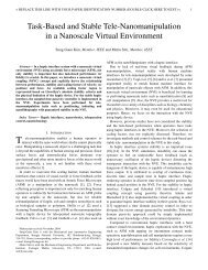
on glass<br />
on polyurethane<br />
Friction Coefficient<br />
1.5<br />
1<br />
0.5<br />
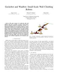
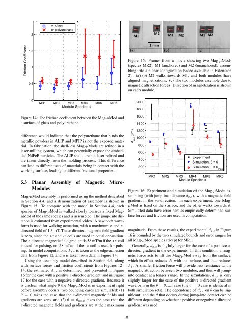
Figure 15: Frames from a movie showing two Mag-µMods<br />
(species MR2), M1 (anchored) <strong>and</strong> M2 (unanchored), assembling<br />
into a planar configuration (video available in Extension<br />
2). (a)-(b) M2 walks towards M1, <strong>and</strong> both modules have<br />
aligned magnetizations. (c) The two modules assemble due to<br />
magnetic attraction forces. Direction <strong>of</strong> magnetization is shown<br />
on each module.<br />
0<br />
MR1 MR2 MR3 MR4 MR5 MR6<br />
Module Species #<br />
2000<br />
1800<br />
Figure 14: The friction coefficient between the Mag-µMod <strong>and</strong><br />
a surface <strong>of</strong> glass <strong>and</strong> polyurethane.<br />
difference would indicate that the polyurethane that binds the<br />
metallic powders in ALIP <strong>and</strong> MPIP is not the exposed material.<br />
In fabrication, the shell-less Mag-µMods are refined in a<br />
laser-milling system, which can potentially expose the embedded<br />
NdFeB particles. The ALIP shells are not laser-refined <strong>and</strong><br />
are taken directly from the molding process. This difference<br />
can lead to different sets <strong>of</strong> materials being in contact with the<br />
working surface, leading to different frictional properties.<br />
5.3 Planar <strong>Assembly</strong> <strong>of</strong> <strong>Magnetic</strong> <strong>Micro</strong>-<br />
Modules<br />
Mag-µMod assembly is performed using the method described<br />
in Section 4.4, <strong>and</strong> a demonstration <strong>of</strong> assembly is shown in<br />
Figure 15. To compare with the model in Section 4.4, each<br />
species <strong>of</strong> Mag-µMod is walked slowly towards a fixed Mag-<br />
µMod <strong>of</strong> the same species <strong>and</strong> is assembled. The jump-into distance<br />
is estimated from experimental video. A sawtooth waveform<br />
is used for walking actuation, with a maximum x <strong>and</strong> z-<br />
directed field <strong>of</strong> 1.3 mT. The x-directed magnetic field gradient<br />
is zero, since the +x <strong>and</strong> -x coils are used in equal opposition.<br />
The z-directed magnetic field gradient is 58 mT/m if the +z-coil<br />
is used for pulsing, or -58 mT/m if the -z-coil is used for pulsing.<br />
In model computations, F s,e is taken as the edge-adhesion<br />
data from Figure 12, <strong>and</strong> µ is taken from data in Figure 14.<br />
Using the assembly model described in Section 4.4, along<br />
with surface forces <strong>and</strong> friction coefficients from Figures 12–<br />
14, the estimated d x,c is determined, <strong>and</strong> presented in Figure<br />
16 for the case with a positive z-directed gradient, <strong>and</strong> in Figure<br />
17 for the case with a negative z-directed gradient. Because it<br />
is unclear what angle θ the Mag-µMod is in experiment right<br />
before assembly occurs, two bounding cases are simulated: (1)<br />
θ = 0 takes the case that the z-directed magnetic fields <strong>and</strong><br />
gradients are zero, <strong>and</strong> (2) θ = θ max takes the case that the<br />
z-directed magnetic fields <strong>and</strong> gradients are at their maximum<br />
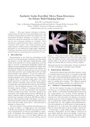
d x,c<br />
(µm)<br />
1600<br />
1400<br />
1200<br />
1000<br />
800<br />
600<br />
400<br />
200<br />
0<br />
Experiment<br />
Simulation, θ = 0<br />
Simulation, θ = θ max<br />
MR1 MR2 MR3 MR4 MR5 MR6<br />
Module Species #<br />
Figure 16: Experiment <strong>and</strong> simulation <strong>of</strong> the Mag-µMods assembling<br />
(with jump-into distance d x,c ), with a magnetic field<br />
gradient in the +z-direction. In each experiment, one Mag-<br />
µMod is fixed on the surface, <strong>and</strong> the other walks towards it.<br />
Simulated data have error bars as empirically determined surface<br />
forces <strong>and</strong> friction are used in computation.<br />
magnitude. From these results, the experimental d x,c in Figure<br />
16 is bounded by the two simulated bounds <strong>and</strong> error ranges for<br />
all Mag-µMod species except for MR1.<br />
Generally, d x,c is slightly larger for the case <strong>of</strong> a positive z-<br />
directed gradient in the experiments. In this condition, a magnetic<br />
force acts to lift the Mag-µMod away from the surface,<br />
which in effect reduces N with the surface, <strong>and</strong> thus reduces<br />
F f . A smaller friction force will provide less resistance to the<br />
magnetic attraction between two modules, <strong>and</strong> thus will jumpinto<br />
contact at a longer range. In the simulations, d x,c is only<br />
slightly larger for the case <strong>of</strong> the positive z-directed gradient<br />
waveform in the θ = θ max case (the θ = 0 case is identical in<br />
both simulation sets). The dependence <strong>of</strong> d x,c on θ can be significant,<br />
<strong>and</strong> the θ that occurs during jump-into contact can be<br />
different depending on whether a positive or negative z-directed<br />
gradient was used.<br />
10