Assembly and Disassembly of Magnetic Mobile Micro-Robots ...
Assembly and Disassembly of Magnetic Mobile Micro-Robots ...
Assembly and Disassembly of Magnetic Mobile Micro-Robots ...

Create successful ePaper yourself
Turn your PDF publications into a flip-book with our unique Google optimized e-Paper software.
y<br />
z<br />
T ec<br />
x<br />
F f<br />
F s,e -N<br />
+z coil<br />
M1<br />
-z coil<br />
m 1<br />
W b<br />
F ec<br />
θ<br />
Surface<br />
+x coil<br />
y<br />
z<br />
x<br />
W b<br />
F ec + F i<br />
L m<br />
M1 m 1<br />
H<br />
F<br />
M2<br />
s,i<br />
m<br />
N m 2<br />
i P c1<br />
F f,i<br />
T ec +T i<br />
F s,f<br />
F f<br />
m2<br />
P r1<br />
N<br />
M2'<br />
P r2<br />
m 2<br />
M2"<br />
Surface<br />
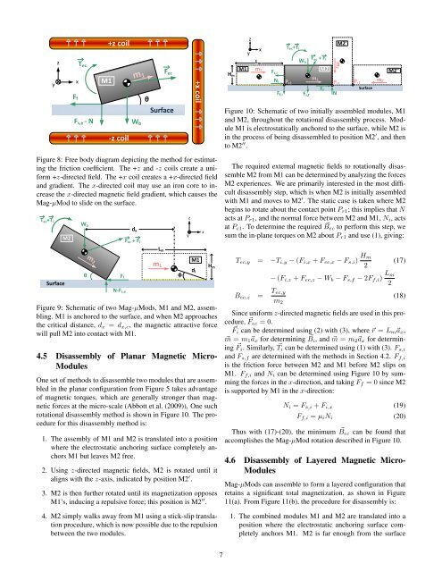
Figure 10: Schematic <strong>of</strong> two initially assembled modules, M1<br />
<strong>and</strong> M2, throughout the rotational disassembly process. Module<br />
M1 is electrostatically anchored to the surface, while M2 is<br />
in the process <strong>of</strong> being disassembled to position M2 ′ , <strong>and</strong> then<br />
to M2 ′′ .<br />
Figure 8: Free body diagram depicting the method for estimating<br />
the friction coefficient. The +z <strong>and</strong> -z coils create a uniform<br />
+z-directed field. The +x coil creates a +x-directed field<br />
<strong>and</strong> gradient. The x-directed coil may use an iron core to increase<br />
the x-directed magnetic field gradient, which causes the<br />
Mag-µMod to slide on the surface.<br />
T ec +T i<br />
Surface<br />
M2<br />
W b<br />
θ<br />
m 2<br />
F f<br />
N-F s,e<br />
d x<br />
F ec + F i<br />
Figure 9: Schematic <strong>of</strong> two Mag-µMods, M1 <strong>and</strong> M2, assembling.<br />
M1 is anchored to the surface, <strong>and</strong> when M2 approaches<br />
the critical distance, d x = d x,c , the magnetic attractive force<br />
will pull M2 into contact with M1.<br />
4.5 <strong>Disassembly</strong> <strong>of</strong> Planar <strong>Magnetic</strong> <strong>Micro</strong>-<br />
Modules<br />
One set <strong>of</strong> methods to disassemble two modules that are assembled<br />
in the planar configuration from Figure 5 takes advantage<br />
<strong>of</strong> magnetic torques, which are generally stronger than magnetic<br />
forces at the micro-scale (Abbott et al. (2009)). One such<br />
rotational disassembly method is shown in Figure 10. The procedure<br />
for this disassembly method is:<br />
L m<br />
m 1<br />
1. The assembly <strong>of</strong> M1 <strong>and</strong> M2 is translated into a position<br />
where the electrostatic anchoring surface completely anchors<br />
M1 but leaves M2 free.<br />
2. Using z-directed magnetic fields, M2 is rotated until it<br />
aligns with the z-axis, indicated by position M2 ′ .<br />
3. M2 is then further rotated until its magnetization opposes<br />
M1’s, inducing a repulsive force; this position is M2 ′′ .<br />
4. M2 simply walks away from M1 using a stick-slip translation<br />
procedure, which is now possible due to the repulsion<br />
between the two modules.<br />
φ<br />
y<br />
z<br />
M1<br />
d i<br />
x<br />
H m<br />
The required external magnetic fields to rotationally disassemble<br />
M2 from M1 can be determined by analyzing the forces<br />
M2 experiences. We are primarily interested in the most difficult<br />
disassembly step, which is when M2 is initially assembled<br />
with M1 <strong>and</strong> moves to M2 ′ . The static case is taken where M2<br />
begins to rotate about the contact point P r1 ; this implies that N<br />
acts at P r1 , <strong>and</strong> the normal force between M2 <strong>and</strong> M1, N i , acts<br />
at P c1 . To determine the required ⃗ B ec to perform this step, we<br />
sum the in-plane torques on M2 about P r1 <strong>and</strong> use (1), giving:<br />
T ec,y = −T i,y − (F i,x + F ec,x − F s,i ) H m<br />
2<br />
− (F i,z + F ec,z − W b − F s,f − 2F f,i ) L m<br />
2<br />
(17)<br />
B ec,z = T ec,y<br />
m 2<br />
(18)<br />
Since uniform z-directed magnetic fields are used in this procedure,<br />
⃗ F ec = 0.<br />
⃗F i can be determined using (2) with (3), where ⃗r = L m ⃗a x ,<br />
⃗m = m 1 ⃗a x for determining ⃗ B i , <strong>and</strong> ⃗m = m 2 ⃗a x for determining<br />
⃗ F i . Similarly, ⃗ T i can be determined using (1) with (3). F s,i<br />
<strong>and</strong> F s,f are determined with the methods in Section 4.2. F f,i<br />
is the friction force between M2 <strong>and</strong> M1 before M2 slips on<br />
M1. F f,i <strong>and</strong> N i can be determined using Figure 10 by summing<br />
the forces in the x-direction, <strong>and</strong> taking F f = 0 since M2<br />
is supported by M1 in the x-direction:<br />
N i = F s,i + F i,x (19)<br />
F f,i = µ i N i (20)<br />
Thus with (17)-(20), the minimum ⃗ B ec can be found that<br />
accomplishes the Mag-µMod rotation described in Figure 10.<br />
4.6 <strong>Disassembly</strong> <strong>of</strong> Layered <strong>Magnetic</strong> <strong>Micro</strong>-<br />
Modules<br />
Mag-µMods can assemble to form a layered configuration that<br />
retains a significant total magnetization, as shown in Figure<br />
11(a). From Figure 11(b), the procedure for disassembly is:<br />
1. The combined modules M1 <strong>and</strong> M2 are translated into a<br />
position where the electrostatic anchoring surface completely<br />
anchors M1. M2 is far enough from the surface<br />
7