Waalbot - NanoRobotics Lab - Carnegie Mellon University
Waalbot - NanoRobotics Lab - Carnegie Mellon University
Waalbot - NanoRobotics Lab - Carnegie Mellon University

You also want an ePaper? Increase the reach of your titles
YUMPU automatically turns print PDFs into web optimized ePapers that Google loves.
330 IEEE/ASME TRANSACTIONS ON MECHATRONICS, VOL. 12, NO. 3, JUNE 2007<br />
<strong>Waalbot</strong>: An Agile Small-Scale Wall-Climbing Robot<br />
Utilizing Dry Elastomer Adhesives<br />
Michael P. Murphy, Student Member, IEEE, and Metin Sitti, Fellow, IEEE<br />
Abstract—This paper proposes a small-scale agile wall-climbing<br />
robot, which is able to climb on smooth vertical surfaces using flat<br />
adhesive elastomer materials for attachment. Using two actuated<br />
legs with rotary motion and two passive revolute joints at each<br />
foot, this robot can climb and steer in any orientation. Due to its<br />
compact design, a high degree of miniaturization is possible. It has<br />
onboard power, computing, and wireless communication, which<br />
allow for semiautonomous operation. Various aspects of a functioning<br />
prototype design and performance are discussed in detail,<br />
including leg and foot design and gait dynamics. A model for the<br />
adhesion requirements and performance is developed and verified<br />
through experiments. Using an adhesive elastomer (Vytaflex 10),<br />
the current prototype can climb 90 ◦ slopes at a speed of up to 6 cm/s<br />
and steer to any angle reliably on a smooth acrylic surface as well<br />
as transition from floor walking to wall climbing. This robot is intended<br />
for inspection and surveillance applications, and ultimately,<br />
for space missions.<br />
Index Terms—Dry adhesives, mechatronics, miniature robotics,<br />
mobile robotics, wall climbing.<br />
I. INTRODUCTION<br />
MOBILE robots with the ability to climb and navigate on<br />
surfaces of any orientation without leaving residue or<br />
damaging the surface have many potential applications. One<br />
notable situation where such a robot could be useful, and perhaps<br />
life-saving, is for spacecraft hull inspection and repair.<br />
Terrestrial uses include surveillance or inspection in hazardous<br />
or difficult-to-reach areas.<br />
Researchers have proposed a great variety of climbing robots<br />
for various applications. Many of the first wall-scaling robots<br />
were intended for cleaning in hazardous environments such as<br />
nuclear reactors [1]. In general, climbing robots use one of three<br />
types of attachment mechanisms: vacuum suction [1]–[7], magnetic<br />
attraction [8], or gripping with claws or grasping mechanism<br />
[9], [10]. Each of these mechanisms has advantages and<br />
drawbacks. For instance, magnetic adhesion can be very strong<br />
with the possibility of safe power failure mitigation, but is<br />
only applicable for ferromagnetic surfaces. Suction adhesion<br />
relies on a complete seal with the surface, making cracked or<br />
nonsmooth surfaces problematic, and power efficiency limits<br />
their untethered climbing duration. Recently, robots using microclaws<br />
have demonstrated climbing capabilities on surfaces<br />
Manuscript received March 1, 2006; revised December 15, 2006. Recommended<br />
by Guest Editors H.-P. Huang and F.-T. Cheng.<br />
M. Murphy is with the <strong>NanoRobotics</strong> <strong>Lab</strong>oratory, Department of Mechanical<br />
Engineering, <strong>Carnegie</strong> <strong>Mellon</strong> <strong>University</strong>, Pittsburgh, PA 15213-3890 USA.<br />
(e-mail: MikeMurphy@cmu.edu).<br />
M. Sitti is with the <strong>NanoRobotics</strong> <strong>Lab</strong>oratory, Department of Mechanical Engineering,<br />
<strong>Carnegie</strong> <strong>Mellon</strong> <strong>University</strong>, Pittsburgh, PA 15213-3890 USA, and<br />
also with the Robotics Institute, <strong>Carnegie</strong> <strong>Mellon</strong> <strong>University</strong>, Pittsburgh, PA<br />
15213-3890 USA (e-mail: sitti@cmu.edu).<br />
Digital Object Identifier 10.1109/TMECH.2007.897277<br />
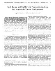
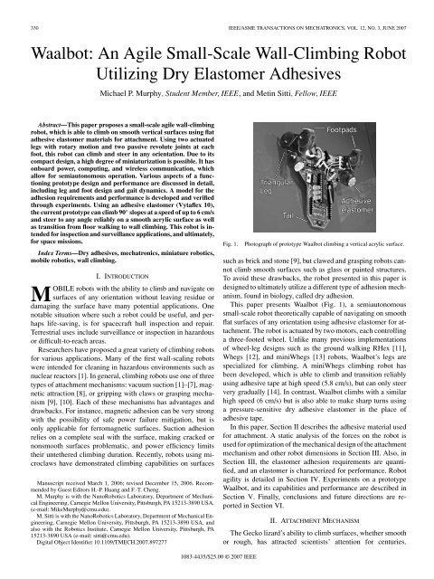
Fig. 1.<br />
Photograph of prototype <strong>Waalbot</strong> climbing a vertical acrylic surface.<br />
such as brick and stone [9], but clawed and grasping robots cannot<br />
climb smooth surfaces such as glass or painted structures.<br />
To avoid these drawbacks, the robot presented in this paper is<br />
designed to ultimately utilize a different type of adhesion mechanism,<br />
found in biology, called dry adhesion.<br />
This paper presents <strong>Waalbot</strong> (Fig. 1), a semiautonomous<br />
small-scale robot theoretically capable of navigating on smooth<br />
flat surfaces of any orientation using adhesive elastomer for attachment.<br />
The robot is actuated by two motors, each controlling<br />
a three-footed wheel. Unlike many previous implementations<br />
of wheel-leg designs such as the ground walking RHex [11],<br />
Whegs [12], and miniWhegs [13] robots, <strong>Waalbot</strong>’s legs are<br />
specialized for climbing. A miniWhegs climbing robot has<br />
been developed, which is able to climb and transition reliably<br />
using adhesive tape at high speed (5.8 cm/s), but can only steer<br />
very gradually [14]. In contrast, <strong>Waalbot</strong> climbs with a similar<br />
high speed (6 cm/s) but is also able to make sharp turns using<br />
a pressure-sensitive dry adhesive elastomer in the place of<br />
adhesive tape.<br />
In this paper, Section II describes the adhesive material used<br />
for attachment. A static analysis of the forces on the robot is<br />
used for optimization of the mechanical design of the attachment<br />
mechanism and other robot dimensions in Section III. Also, in<br />
Section III, the elastomer adhesion requirements are quantified,<br />
and an elastomer is characterized for performance. Robot<br />
agility is detailed in Section IV. Experiments on a prototype<br />
<strong>Waalbot</strong>, and its capabilities and performance are described in<br />
Section V. Finally, conclusions and future directions are reported<br />
in Section VI.<br />
II. ATTACHMENT MECHANISM<br />
The Gecko lizard’s ability to climb surfaces, whether smooth<br />
or rough, has attracted scientists’ attention for centuries.<br />
1083-4435/$25.00 © 2007 IEEE
MURPHY AND SITTI: WAALBOT: AN AGILE SMALL-SCALE WALL-CLIMBING ROBOT UTILIZING DRY ELASTOMER ADHESIVES 331<br />
By means of compliant micro/nanoscale high-aspect-ratio<br />
beta-keratin structures on their feet, geckos and spiders manage<br />
to adhere to almost any surface with a controlled contact area<br />
[15]. It has been shown that adhesion is mainly due to molecular<br />
forces such as van der Waals forces [16] (from which <strong>Waalbot</strong><br />
draws its name). Tiny fibers on the animals’ feet form weak attractive<br />
bonds with the surface, and the combination of billions<br />
of contacting fibers creates a large adhesion (up to 100 kPa).<br />
Since dry adhesion does not rely heavily on the surface material<br />
or atmospheric pressure, it allows climbing on a wide variety of<br />
surfaces, and is uniquely suitable for use in the vacuum of space.<br />
Synthetic fibrillar dry adhesive technology is not currently<br />
mature enough to be used for climbing robots, however, <strong>Waalbot</strong><br />
is designed with the intention of eventually utilizing this<br />
technology. While efforts to develop the synthetic fibrillar dry<br />
adhesive continue [17]–[21], the robot uses polymer adhesive<br />
material (Smooth-On Vytaflex 10), which shares many performance<br />
characteristics with the envisioned dry adhesive material.<br />
Both the dry adhesive and the elastomer adhesive must be<br />
pressed to the surface with a preload force in order to provide an<br />
adhesive force on detachment. Like fiber-based biological adhesives,<br />
compliant elastomers gain their adhesion performance by<br />
deforming into the microscale surface features of any smooth<br />
surface and creating a large contact area. V10 is highly compliant<br />
with a Shore-A hardness rating of 10, and exhibits tack while<br />
leaving no residue. Using these adhesives as substitutes until the<br />
fiber-based dry adhesives have suitable performance for this application<br />
allows testing and improvements to the robot design.<br />
The adhesive elastomer is characterized for its adhesion through<br />
testing on a custom system. A sample is moved into contact with<br />
a substrate that is connected to a high-resolution load cell by an<br />
automated stage. When the pressing force reaches a specified<br />
preloading value the sample is retracted. The adhesive force is<br />
recorded as the maximum force before separation, and force<br />
values are converted to pressures by dividing the area of the<br />
sample. Fig. 2(a) is a force versus time plot showing the preload<br />
(point P 1 ) and maximum adhesion value (point P 2 ) from a single<br />
experiment. A series of these experiments are performed by<br />
varying the preload value and a plot of the adhesion results form<br />
a performance curve for the adhesive–substrate combination as<br />
shown in Fig. 2(b). This performance curve is typical for the adhesive<br />
elastomer tested. The adhesion is greater than the preload<br />
pressure for low preload pressures. For higher preload pressures<br />
the performance curve saturates at a maximum adhesion value.<br />
III. ROBOT DESIGN<br />
A. Mechanical Design<br />
<strong>Waalbot</strong>’s overall mechanical design is discussed in previous<br />
work [20]; this section describes the selection of physical<br />
parameters for improved performance over initial prototypes.<br />
In order to create a preload force sufficient to bring the adhesive<br />
into intimate contact with the surface, a robot should be<br />
designed to maximize the pressing force when the adhesive pads<br />
come into contact with the climbing surface. This requirement<br />
guides the design of the legs and feet. A gear motor’s output<br />
shaft is connected to a triangular shaped leg (Fig. 3), where<br />
Fig. 2. (a) Typical force versus time data plot for a single adhesion test where<br />
P 1 corresponds to the preload and P 2 corresponds to the adhesion. (b) Performance<br />
curve for a flat V10 elastomer on a smooth acrylic surface.<br />
Fig. 3. CAD model of the Tri-Foot design (left) and a photograph of the<br />
assembled prototype components (right). Each foot pad has two degrees of<br />
freedom enabling climbing and steering. Axis A allows the foot to rotate to<br />
maintain contact with the surface. Axis B allows for footpad rotation.<br />
each point of the triangle holds a foot assembly on a revolute<br />
ankle joint (A). The ankle joint assembly is spring loaded to<br />
always return to the forward position (the robot cannot travel in<br />
reverse).<br />
On the distal end of the foot assembly is a passive revolute<br />
joint (B) connecting a foot pad, which holds the adhesive material.<br />
This distal joint enables steering capabilities (discussed<br />
later in Section IV). The principle of operation is as follows.<br />
During forward travel the two legs are synchronized and step in<br />
unison. As the motors turn, the tail of the robot presses against<br />
the surface, and the triangular legs rotate forward. The two feet<br />
adhered to the surface (one on each side) support the weight<br />
of the robot [Fig. 4(a)]. Soon after, the forward feet come into<br />
contact with the surface [Fig. 4(b)]. At this point there are five<br />
contact points with the surface: two feet on each side and the tail.<br />
The motor torque provides an internal moment, which presses<br />
the front feet onto the surface while pulling the rear feet away<br />
from the surface. When the rear foot normal force F Rn reaches
332 IEEE/ASME TRANSACTIONS ON MECHATRONICS, VOL. 12, NO. 3, JUNE 2007<br />
Fig. 4.<br />
Still-photograph frames of <strong>Waalbot</strong> climbing a vertical surface.<br />
TABLE I<br />
PHYSICAL PARAMETERS FOR THE ROBOT MODEL<br />
Fig. 5. Free body diagrams showing the forces during a forward step (a) where<br />
the front foot is pressed against the surface and the rear foot is peeled, and (b) in<br />
the configuration in which the robot experiences the highest peeling force while<br />
climbing.<br />
a critical peeling value of F cr , the adhesive peels away from the<br />
surface and the robot steps forward.<br />
1) Preload-To-Peeling Ratio Analysis: Examining the free<br />
body diagram [Fig. 5(a)] and assuming quasi-static dynamics<br />
and symmetric loading, it is possible to find a system of equations<br />
that describe the forces on the robot during the stepping<br />
transfer, represented as<br />
∑<br />
Fy =0=F t + F Rn + F Fn − W cos θ<br />
∑<br />
Fx =0=F Rx + F Fx − W sin θ<br />
∑<br />
Mc =0=(F Rn − F Fn )( d step<br />
2 )<br />
+ F t (L t )+W sin θ(L yc − L ycg )<br />
− (F Rx + F Fx )(L yc ) − W cos θ(L xcg ) (1)<br />
where W is the weight; θ is the slope of the climbing surface;<br />
F t ,F Rn ,F Fn are the normal forces at the tail, rear foot, and<br />
front foot, respectively. F Rx and F Fx are the shear forces on the<br />
rear and front feet, respectively. d step is the distance between<br />
the centers of the rear and front feet, L yc is the distance from<br />
the climbing surface to the center of the leg, and L ycg ,L xcg are<br />
the distances from the center of gravity (C g ) to the surface and<br />
center of the leg, respectively. L t is the distance between the<br />
center of the leg and the tail–surface contact point. There are<br />
five unknown forces (F Fn ,F Rn ,F Fx ,F Rx , and F t ) and only<br />
three equations, therefore, to solve for the unknowns two assumptions<br />
must be made. Assuming F Rn = −F cr will give the<br />
forces just before the peel-off occurs, which is when F Fn is at<br />
a maximum. We also assume that the shear forces on the front<br />
and rear feet are equal (F Fx = F Rx ). Physical parameters for<br />
the model are given in Table 1.<br />
Fig. 6. Plot of preload-to-peeling force ratio for all values of surface slope<br />
angle θ with a minimum at 160 ◦ (A), a maximum at 340 ◦ (B), and a 1:1 ratio<br />
at 11 ◦ and 306 ◦ (C, D).<br />
Using these values, assumptions, and (1), it is possible to examine<br />
the effect of slope angle θ on the preload force F Fn . Since<br />
this preload force presses the adhesive into intimate contact and<br />
enables adhesion, it is of critical importance. Specifically, the<br />
ratio between the critical peel-off force F cr and the preload<br />
force determines the requirements for the adhesive, which are<br />
discussed in Section III-B. Using the <strong>Waalbot</strong> prototype geometry<br />
and specifications, the relationship between this ratio and<br />
the slope angle is found (Fig. 6).<br />
The graph indicates that for the prototype <strong>Waalbot</strong> there is<br />
a reduction of this ratio up to 73% depending on the climbing<br />
angle, with a minimum of 0.266:1 at 160 ◦ (close to inverted<br />
climbing), meaning that for sustainable climbing the adhesive<br />
must consistently provide four times as much adhesion as the<br />
force it was preloaded with. The details of this requirement are<br />
described in the following section.<br />
2) Critical Peeling Force Analysis: The adhesives have high<br />
shear resistance, therefore, detachment occurs due to the normal<br />
force pulling the foot away from the surface. The minimum<br />
adhesive normal force required to keep the robot attached to the
MURPHY AND SITTI: WAALBOT: AN AGILE SMALL-SCALE WALL-CLIMBING ROBOT UTILIZING DRY ELASTOMER ADHESIVES 333<br />
wall during climbing can be found by examining the case when<br />
only one foot per side is attached and the C g is at its furthest<br />
distance from the surface [(Fig. 5(b)]. The quasi-static equation<br />
for this case giving a maximum force that the adhesives must be<br />
able to provide is represented as<br />
F Rn = W L t<br />
(<br />
Lycg(max) sin θ − (L t − L xcg )cosθ ) . (2)<br />
If this force exceeds the magnitude of F cr then, the robot will<br />
detach from the surface. Therefore, this equation gives the minimum<br />
adhesive performance needed to climb. Because of the<br />
consequences of a fall, a safety factor is used when choosing an<br />
adhesive and adhesive foot area. Graphing this function with the<br />
known design parameters of the robot, it is possible to find the<br />
maximum peeling force over all angles. For the prototype parameters<br />
the maximum peeling force occurs at a climbing angle<br />
of 160 ◦ . The corresponding minimum for the critical peeling<br />
force of the adhesive F cr is 0.43 N. This value must be supported<br />
by the adhesives for the robot to climb on surfaces of all<br />
slope angles, and represents one of the adhesive requirements.<br />
From (2), it is clear that in order to minimize the peeling force<br />
on the adhesive pad during climbing, the length of the tail should<br />
be increased, and the center of gravity should be moved close<br />
to the wall. Also, the weight of the robot should be minimized.<br />
This can be accomplished through fabricating the robot from<br />
lighter materials or through miniaturization. Miniaturization is<br />
advantageous to this robot design because mass is proportional<br />
to L 3 while the adhesion is proportional to area, i.e., L 2 , where<br />
L is the characteristic length. As the robot shrinks in size, the<br />
adhesion becomes less than the gravitational force, so we see an<br />
increase in the performance of the robot.<br />
Both (1) and (2) suggest that the tail should be long to increase<br />
the preload force and to minimize the peeling force. However, it<br />
is important to note that the weight of the robot is also increased<br />
with the tail length, so there is a coupling between W and L t .<br />
Furthermore, a longer tail increases the amount of room necessary<br />
for turning, as the tail may sweep out and contact obstacles<br />
causing the robot to lose adhesion and fall. So a longer tail limits<br />
the ability to climb in small areas. Therefore, for maximum performance<br />
without compromising agility, the tail length is chosen<br />
to be the longest length possible while remaining fully within<br />
the turning circle (described in Section IV). With these parameters<br />
fixed, it is necessary to examine the adhesive to determine<br />
whether these requirements can be met.<br />
B. Adhesive Requirements<br />
The values from Figs. 2 and 6 and (2) are used to create a set<br />
of requirements for the adhesive. For the <strong>Waalbot</strong> to have the<br />
ability to climb on vertical surfaces of θ =90 ◦ , the operating<br />
critical peeling force must be no less than 0.16 N (2) and the<br />
adhesive must hold with a minimum of two times as much<br />
force as it was preloaded with (Fig. 6) at this operating peeling<br />
force. To visualize such a requirement it is convenient to plot<br />
an adhesive–substrate performance curve with bounds, which<br />
represent the requirements as in Fig. 7. Using this representation<br />
Fig. 7. Performance curve plotted with ratio lines for various surface slope<br />
angles. For a surface slope of 90 ◦ , the adhesives converge to the steady-state<br />
operating preload and adhesion (s). L ∞ and F ∞ indicate the steady-state operating<br />
preload and adhesion pressure for this slope angle, respectively. F safe<br />
indicates a minimum safe adhesion pressure, and the difference between these<br />
values is the margin of safety M s .<br />
it is possible to determine if an adhesive is suitable, and if it is<br />
what the minimum footpad size must be.<br />
In Fig. 7, the performance curve is plotted along with lines<br />
of various slopes (m(θ)) called “ratio lines” for θ values of<br />
160 ◦ , 90 ◦ , 60 ◦ , 0 ◦ , and 340 ◦ . These slopes are the inverse of the<br />
ratio of adhesion-to-preload (Fig. 6). The case when the robot<br />
is climbing on a surface oriented at 160 ◦ was found to be the<br />
most challenging [(2), Fig. 6], and appears here as the steepest<br />
ratio line while the slope of 340 ◦ was found to be the easiest,<br />
and has the ratio line with the lowest slope. Ratio lines for all<br />
other slope angles fall between these two extremes. In general,<br />
the equation of a ratio line is<br />
F = m(θ)L (3)<br />
where F is the adhesion pressure, L is the preload pressure, and<br />
m is the slope. The performance curve of the adhesive–surface<br />
combination [Fig. 2(b)] can be approximated by a power law<br />
function (which has similar rising curve and saturation behavior)<br />
with general form<br />
F = aL 1/n (4)<br />
where n>1 and a is a scaling coefficient. The preload value at<br />
the intersection of the two lines (L ∗ )isgivenby<br />
( a<br />
n<br />
L ∗ n −1<br />
= . (5)<br />
m)<br />
For each step the robot has an initial preload L i . The maximum<br />
peeling pressure F i is determined by the performance<br />
curve. This maximum adhesion pressure is transferred to the<br />
preload pressure for the next step with a force ratio of 1/m.<br />
To determine the steady-state operating adhesion and preload<br />
(the pressures at which the feet will press onto and adhere to<br />
the surface after many steps), we examine an iterative function<br />
where each iteration represents one forward step of the robot.
334 IEEE/ASME TRANSACTIONS ON MECHATRONICS, VOL. 12, NO. 3, JUNE 2007<br />
It can be shown that the preload converges to the intersection<br />
preload (L ∗ ) through an iterative proof using the update rule<br />
( a<br />
L i+1 = L<br />
m)<br />
( 1 n )<br />
i (6)<br />
which mathematically represents a single step, where L i is the<br />
preload for step number i. The steady-state operating preload<br />
(L ∞ ) is given by<br />
( a<br />
) A<br />
(<br />
L ∞ = lim L 1 n )<br />
n→∞<br />
0 (7)<br />
m<br />
A =1+ 1 (<br />
1+ 1 (1+ 1 ))<br />
n n n (...) = n<br />
n − 1 . (8)<br />
Therefore,<br />
( a<br />
n<br />
n −1<br />
L ∞ = = L<br />
m) ∗ . (9)<br />
The steady-state operating preload (L ∞ ) converges to the<br />
preload at the intersection of the two lines (L ∗ ) from (5). The<br />
steady-state operating adhesion (F ∞ ) is then equal to mL ∞ .<br />
These two values define a steady-state operating point, point S<br />
in Fig. 7. There is also a minimum safe adhesion value (F safe ),<br />
which is a function of the area of the footpads and the surface<br />
slope angle θ, and can be calculated from (2) and foot size. The<br />
steady state operating adhesion (F ∞ ) must be greater than the<br />
minimum safe adhesion value (F safe ) to prevent the robot from<br />
detaching from the climbing surface. The margin between the<br />
steady-state operating adhesion and the minimum safe adhesion<br />
is the margin of safety (M s ). Since the robot will not always<br />
have ideal force transfer on every step, it is important to have a<br />
large margin of safety so that the robot can recover from a problematic<br />
step, or continue to operate if the adhesives become<br />
contaminated and function with degraded performance.<br />
It is possible to increase the margin of safety by increasing<br />
the area of the adhesives (foot pad size), which lowers the<br />
minimum adhesion pressure requirement. However, there is a<br />
tradeoff because the motors then need to provide more torque to<br />
peel the larger feet. This causes an increased power requirement,<br />
which leads to larger batteries, and also necessitates a larger and<br />
heavier motor.<br />
C. Robot Fabrication<br />
A printed circuit board (PCB) acts as the chassis for the robot<br />
instead of using an additional body frame in order to keep the<br />
mass low. The leg and feet assemblies are fabricated via 3-D<br />
printing (Z-Corp. ZPrinter and 3-D Systems Invision HR). The<br />
heaviest components of the system are the leg assemblies, motors,<br />
and batteries. In order to move the center of gravity as close<br />
as possible to the surface and balanced around the motor axes, all<br />
these parts are located close to the shaft axes with the batteries<br />
beneath the PCB, nearly in contact with the climbing surface.<br />
The robot is controlled by a PIC microcontroller<br />
(PIC16F737), and is able to perform preprogrammed actions<br />
such as climbing and turning without instructions from the user.<br />
Gait is controlled with feedback from foot position sensors.<br />
Limit switches are triggered when the legs are aligned so that<br />
only one foot on each side is in contact with the surface. This<br />
Fig. 8. <strong>Waalbot</strong>’s small turning radius (R t ) and turning circle radius (R tc )<br />
allow it to climb around obstacles, and operate in narrow corridors with sharp<br />
bends.<br />
information is used to keep the robot’s gait synchronized by<br />
pausing one of the motors until the opposing motor catches up,<br />
assuring that the assumptions of symmetry in (1) are valid. Foot<br />
position tracking is also important for safely putting the robot<br />
into steering mode. Infrared (IR) RC5 communication is used<br />
to teleoperate the robot to climb straight, stop, and turn. Commands<br />
can be sent for turning 180 ◦ , 90 ◦ , and in increments of<br />
15 ◦ in either direction.<br />
Power is provided by two lithium ion polymer batteries which<br />
are placed in series beneath the body of the robot for 7.4 V.<br />
The two motors (Sanyo 12GA-N4s) have a torque output of<br />
approximately 400 mN.m each, which is sufficient to peel the<br />
rear feet from the surface.<br />
IV. AGILITY<br />
A. Steering<br />
When only one foot on a side is in contact with the surface,<br />
that foot can be used as a pivot point for the robot to rotate about.<br />
By advancing the opposite motor, the robot rotates around the<br />
passive revolute joint in the pivoting foot. If the robot attempted<br />
to turn while the two feet were attached on a side, the robot<br />
would shear itself off the surface, since the center of rotation<br />
would not be aligned with a joint. Since this can be a catastrophic<br />
failure for a climbing robot, foot position sensors are used to<br />
prevent this occurrence.<br />
In steering mode, the robot takes discrete steps around the<br />
pivoting foot. The turning radius is less than the width of the<br />
robot, which allows tight turns (Fig. 8). The ability to make<br />
tight turns is an important feature for climbing through small<br />
passageways or for avoiding closely spaced obstacles.<br />
Steering angle per step can be calculated from the turning<br />
radius R t and the stepping distance d step by examining the<br />
triangle between the pivot, front, and rear stepping feet as<br />
( )<br />
θ =cos −1 1 − d2 step<br />
2Rt<br />
2 (10)
MURPHY AND SITTI: WAALBOT: AN AGILE SMALL-SCALE WALL-CLIMBING ROBOT UTILIZING DRY ELASTOMER ADHESIVES 335<br />
TABLE II<br />
SPECIFICATIONS OF THE ROBOT PROTOTYPE IN EXPERIMENTS<br />
planes is known. It may be possible to incorporate capabilities<br />
to calculate this optimal foot placement when a new plane is<br />
detected, and then plan a sequence to transition successfully.<br />
A prototype <strong>Waalbot</strong> was built according to the design aspects<br />
previously mentioned with the specifications given in Table II.<br />
The foot pad area was designed according to the adhesive requirements<br />
for 90 ◦ climbing.<br />
Fig. 9. Schematic side view showing the steps in a 90 ◦ plane transition (top)<br />
and still-photograph frames of the <strong>Waalbot</strong> prototype performing the transition<br />
(bottom).<br />
where the turning radius R t is the lateral distance between the<br />
centers of the feet. Conversely, given a desired stepping angle,<br />
the robot’s dimensions can be designed to achieve this angle.<br />
The prototype <strong>Waalbot</strong> was designed to make discrete turning<br />
increments, which change the heading by 15 ◦ /step. This angle<br />
is convenient as it allows for turns of 45 ◦ , 90 ◦ , and 180 ◦ as well<br />
as smaller adjustments.<br />
B. Plane Transitions<br />
The robot’s unique jointed legs allow it to perform transitions<br />
between planes. For example, the robot can theoretically<br />
climb along a floor and transition to climbing up a vertical wall,<br />
and then, transition onto another wall or a ceiling. The steps<br />
of a transition process are shown in Fig. 9. As the robot approaches<br />
a junction, the forward foot makes contact with the<br />
new plane [Fig. 9(a)], and the robot makes the planar transition<br />
[Fig. 9(b) and (c)]. The Tri-Foot design gives <strong>Waalbot</strong> the capability<br />
of making planar transitions of various angles including<br />
90 ◦ , however, the transitions are not fully robust. This is due<br />
to the nonperpendicular angle at which the forward foot may<br />
contact the new plane. Since the foot position is optimized for<br />
flat surface walking, when a new plane is encountered the foot<br />
may not come into full contact immediately. In this case, the<br />
foot may not be preloaded correctly, and adhesion cannot be<br />
guaranteed. In the worst case, the forward foot may land in the<br />
junction, touching both planes and making very little contact,<br />
causing almost certain failure of adhesion. Therefore, depending<br />
on the relative angles of the approaching foot and the new<br />
plane, the robot may or may not successfully make the transition.<br />
However, for any given angle between the two planes down<br />
to an acute 60 ◦ , there exists a series of foot placements that will<br />
allow for a successful transition. The distance from the final<br />
step in the first plane to the junction determines the angle between<br />
the approaching foot and the new plane, and the optimal<br />
foot placement can be calculated if the angle between the two<br />
V. EXPERIMENTS<br />
A. Force Characterization<br />
A force plate system was created to experimentally confirm<br />
the theory in Section III. To measure the forces during climbing,<br />
the <strong>Waalbot</strong> prototype climbs on an acrylic sheet with a small<br />
circular acrylic panel. This circular panel is supported by a thin<br />
rectangular steel cantilever beam. Using a laser scan micrometer<br />
(Keyence LS-3034) to measure the beam deflection, the force on<br />
the circular panel can be determined. During operation the force<br />
plate moves only a few hundred micrometers, and therefore,<br />
approximates a rigid surface. The force plate system can be<br />
adjusted to any angle so that testing can be done at all surface<br />
slopes.<br />
This test setup allows measurements of normal forces between<br />
the robot and the climbing surface such as F Rn and F Fn<br />
for comparison with (1) and (2).<br />
To validate the results from (2) the <strong>Waalbot</strong> prototype was<br />
placed on the acrylic sheet with one footpad adhered to the force<br />
plate in the configuration from Fig. 5(b). The normal forces were<br />
recorded for surface slopes from 0 ◦ to 180 ◦ at 30 ◦ increments and<br />
at 300 ◦ . The measurement apparatus was calibrated by taking the<br />
measurements without the <strong>Waalbot</strong> so that the weight effects of<br />
the force plate could be removed from the results. The results are<br />
plotted against the theoretical results in Fig. 10. The close match<br />
between the experimental data and (2) confirms the adhesion<br />
requirement model for the direction normal to the surface for<br />
the configuration seen in Fig. 5(b).<br />
Using the same force plate system, we can compare the performance<br />
curve data from material tests (Fig. 7) to its performance<br />
in use on the <strong>Waalbot</strong>. The prototype is directed to step<br />
onto and off the force panel, and the preload and associated<br />
pull-off forces are recorded. The robot was tested with a surface<br />
slope of θ =0for simplicity. The experimental adhesion<br />
and preload pressures are found by dividing the preload and<br />
pull-off forces by the foot area. Fig. 11 shows the experimental<br />
preload pull-off data and material testing performance curves<br />
overlayed for comparison. Here, each data point represents a<br />
single step as the <strong>Waalbot</strong> steps onto and off the force plate, and
336 IEEE/ASME TRANSACTIONS ON MECHATRONICS, VOL. 12, NO. 3, JUNE 2007<br />
Fig. 10. Experimental normal forces (points) agree with theory (line) from<br />
(2) for varying climbing slopes. Error bars indicate the standard deviation of the<br />
measured values.<br />
Fig. 12. Still frames from a video showing a <strong>Waalbot</strong> prototype turning while<br />
climbing on a vertical acrylic surface. The prototype turns 90 ◦ (line overlayed)<br />
in six steps (a)–(f).<br />
Fig. 11. Data from <strong>Waalbot</strong> experiments on force plate overlayed on the<br />
performance curve from material testing (dotted line).<br />
each point is from a different run. Although the data from the<br />
<strong>Waalbot</strong> prototype experiments do not exactly match the performance<br />
curve generated from the material testing, the agreement<br />
is sufficient to demonstrate that the material testing performance<br />
curve is a reasonable estimate for the real robot performance,<br />
and can be a useful tool for selecting an adhesive material and<br />
footpad size. Most of the data points show slightly reduced<br />
adhesion compared to the performance curve data. However,<br />
this is expected since the material testing was carried out in<br />
a highly controlled and physically constrained set of experiments,<br />
whereas the <strong>Waalbot</strong> prototype experiments represent a<br />
larger scale adhesive behavior. Possible sources for discrepancy<br />
include incomplete attachment of the foot pad to the surface,<br />
speed of attachment and detachment, and peeling effects due to<br />
the spring-loaded ankle joint.<br />
B. Climbing Performance<br />
The current <strong>Waalbot</strong> prototype was tested on a smooth clear<br />
acrylic climbing surface. It is capable of climbing any direction<br />
on planes of various orientations. This includes climbing up,<br />
down, or across a vertical (90 ◦ ) surface, all at speeds of up to<br />
6 cm/s, which is limited by the motor speed. The robot climb-<br />
ing speed was measured by examining video of the prototype<br />
climbing up a distance of 30 cm. Similarly, the maximum turning<br />
speed was found to be approximately 37 ◦ /s. The maximum<br />
angle, which the prototype is able to climb, was found to be<br />
110 ◦ (20 ◦ past vertical). The robot is able to remain adhered<br />
to an inverted surface, but detaches when stepping. It was observed<br />
that the footpads peel off from the surface at the leading<br />
edge, indicating that the assumption in our analytical model of<br />
a point force at the center of the foot is not valid, since there is<br />
a nonuniform load across the adhesive surface.<br />
The prototype <strong>Waalbot</strong> is able to make left- and right-hand<br />
turns without falling from the climbing surface (Fig. 12). Both<br />
small and large turning angles are routinely made. The prototype<br />
can be teleoperated to navigate around obstacles while climbing.<br />
The current prototype is capable of making transitions of<br />
various angles, including 90 ◦ . Floor to wall, and wall to floor<br />
transitions were successfully accomplished. Ceiling to wall<br />
and wall to ceiling transitions were not successful. As discussed<br />
in Section IV-B, the transitions are not robust; the<br />
prototype feet often land in the corner causing the robot<br />
to lose adhesion with the climbing surface. Videos of the<br />
prototype performing various agility tasks can be viewed at<br />
http://nanolab.me.cmu.edu/projects/waalbots/tri-leg.html.<br />
VI. CONCLUSION<br />
A wall-climbing robot design was analyzed and implemented.<br />
A quasi-static model was created to determine the forces acting<br />
on the robot. A model for adhesive performance for a climbing<br />
robot was developed, which demonstrates the margin of<br />
safety and steady-state operating points. Design criteria were<br />
established to guide adhesive selection, foot size, and torque<br />
requirements. A semiautonomous tetherless robot prototype was<br />
designed and fabricated, which is able to climb on smooth surfaces<br />
of various orientations including climbing in any direction<br />
on smooth vertical acrylic surfaces using a pressure sensitive<br />
elastomer for attachment. The robot can climb at a speed of 6<br />
cm/s (0.46 body length/s), and turn with a small turning radius
MURPHY AND SITTI: WAALBOT: AN AGILE SMALL-SCALE WALL-CLIMBING ROBOT UTILIZING DRY ELASTOMER ADHESIVES 337<br />
to travel along curved paths and around tight corners. IR communication<br />
is used to control the robot. The prototype was not<br />
able to climb on inverted surfaces because of its high mass, but<br />
was able to climb on smooth acrylic surfaces with slopes up to<br />
110 ◦ and make floor to wall transitions.<br />
Climbing reliability of the prototype was limited because of<br />
the inability of the robot to maintain synchronization between<br />
the two legs. The sensors synchronize the legs only three times<br />
per revolution. Since the motors and drive trains differ slightly<br />
in friction, they run at different speeds. While the sensors are<br />
sufficient for foot positioning for safe turning, they do not provide<br />
synchrony throughout forward steps. When the feet are<br />
stepping even slightly asynchronously the assumptions made<br />
for the robot analysis no longer apply. In this case, the front feet<br />
are not necessarily preloaded correctly and the robot often falls.<br />
Future versions of the <strong>Waalbot</strong> will utilize absolute encoders to<br />
track and synchronize the legs.<br />
One of the major disadvantages of this robot design is that<br />
there is very little redundancy in case of adhesion failure. Most of<br />
the time, there are only two feet attached to the surface. Inverted<br />
climbing was not possible with the prototype due to the mass of<br />
the robot. As the adhesives used on the feet of the robot gathered<br />
dust and other contaminants, their performance degraded<br />
quickly. Therefore, these elastomer adhesives are not suitable<br />
for dirty outdoor environments, walking across indoor floors, or<br />
for long term tasks. Furthermore, if improper foot placement occurs,<br />
the possibility of adhesion failure during a plane transition<br />
is a dangerous flaw for a climbing robot. Sensing and planning<br />
for plane transitions is an important future challenge.<br />
Future work includes implementing the synthetic dry adhesives<br />
in place of the conventional adhesives when the technology<br />
is mature. Further miniaturization of the robots is required to improve<br />
performance due to increased area-to-mass ratio. Decreasing<br />
the robot mass will increase payload capacity, allowing for<br />
other sensors or tools, and lower power consumption for longer<br />
operation time. The force model will be improved by including<br />
the ankle joint as well as nonuniform adhesion pressure distribution<br />
across the surface of the footpads. Initial results from tests<br />
with a new smaller scale prototype, which addresses many of the<br />
issues discussed, show that these challenges can be overcome<br />
and suggest that reliable climbing with this design is possible.<br />
ACKNOWLEDGMENT<br />
The authors would like to thank W. Tso and M. Tanzini for<br />
their robot design, fabrication, and testing assistance, and all the<br />
members of the <strong>NanoRobotics</strong> <strong>Lab</strong>oratory at <strong>Carnegie</strong> <strong>Mellon</strong><br />
<strong>University</strong> for their help and discussions.<br />
REFERENCES<br />
[1] W. Yan, L. Shuliang, X. Dianguo, Z. Yanzheng, S. Hao, and G. Xueshan,<br />
“Development and application of wall-climbing robots,” in Proc. IEEE<br />
Int. Conf. Robot. Autom., 1999, pp. 1207–1212.<br />
[2] S. Hirose, A. Nagakubo, and R. Toyama, “Machine that can walk and<br />
climb on floors, walls and ceilings,” in Proc. Int. Conf. Adv. Robot., 1991,<br />
vol. 1, pp. 753–758.<br />
[3] S. Ryu, J. Park, S. Ryew, and H. Choi, “Self-contained wall-climbing<br />
robot with closed link mechanism,” in Proc. Int. Conf. Intell. Robots Syst.,<br />
2001, vol. 2, pp. 839–844.<br />
[4] L. Briones, P. Bustamante, and M. Serna, “Wall-climbing robot for inspection<br />
in nuclear power plants,” in Proc. Int. Conf. Robot. Autom.,<br />
1994, pp. 1409–1414.<br />
[5] R. Pack, J. L. Christopher, and K. Kawamura, “A rubbertuator-based<br />
structure-climbing inspection robot,” in Proc. IEEE Int. Conf. Robot. Autom.,<br />
Albuquerque, NM, 1997, vol. 3, pp. 1869–1874.<br />
[6] B. Luk, A. Collie, V. Piefort, and G. Virk, “Robug iii: A tele-operated<br />
climbing and walking robot,” in Proc. UKACC Int. Conf. Control, 1996,<br />
vol. 1, pp. 347–352.<br />
[7] T. Yano, T. Suwa, M. Murakami, and T. Yamamoto, “Development of a<br />
semi self-contained wall climbing robot with scanning type suction cups,”<br />
in Proc. Int. Conf. Intell. Robots Syst., 1997, vol. 2, pp. 900–905.<br />
[8] J. Grieco, M. Prieto, M. Armada, and P. Gonzalez de Santos, “A six-legged<br />
climbing robot for high payloads,” in Proc. Int. Conf. Control Appl., 1998,<br />
pp. 446–450.<br />
[9] S. Kim, A. T. Asbeck, M. R. Cutkosky, and W. R. Provancher, “Spinybot<br />
II: Climbing hard walls with compliant microspines,” in Proc. Int. Conf.<br />
Adv. Robot., 2005, pp. 601–606.<br />
[10] T. Bretl, S. Rock, and J.-C. Latombe, “Motion planning for a three-limbed<br />
climbing robot in vertical natural terrain,” in Proc. Int. Conf. Robot. Autom.,<br />
2003, pp. 2947–2953.<br />
[11] R. Altendorfer, N. Moore, H. Komsuoglu, M. Buehler, H. B. B. Jr., D. Mc-<br />
Mordie, U. Saranli, R. Full, and D. Koditschek, “Rhex: A biologically<br />
inspired hexapod runner,” Auton. Robots, vol. 11, no. 3, pp. 207–213,<br />
2001.<br />
[12] R. Quinn, D. Kingsley, J. Offi, and R. Ritzmann, “Improved mobility<br />
through abstracted biological principles,” in Proc. IEEE/RSJ Int. Conf.<br />
Intell. Robots Syst., 2002, pp. 2652–2657.<br />
[13] J. M. Morrey, B. Lambrecht, A. D. Horchler, R. E. Ritzmann, and<br />
R. D. Quinn, “Highly mobile and robust small quadruped robots,” in<br />
Proc. Int. Conf. Intell. Robots Syst., 2003, vol. 1, pp. 82–87.<br />
[14] K. Daltorio, A. D. Horchler, S. Gorb, R. Ritzmann, and R. Quinn, “A<br />
small wall-walking robot with compliant, adhesive feet,” in Proc. Int.<br />
Conf. Intell. Robots Syst., 2005, pp. 4018–4023.<br />
[15] K. Autumn, Y. A. Liang, S. T. Hsieh, W. Zesch, W. P. Chan, T. W. Kenny,<br />
R. Fearing, and R. J. Full, “Adhesive force of a single gecko foot-hair,”<br />
Nature, vol. 405, pp. 681–685, 2000.<br />
[16] K. Autumn, M. Sitti, Y. A. Liang, A. M. Peattie, W. R. Hansen, S. Sponberg,<br />
T. W. Kenny, R. Fearing, J. N. Israelachvili, and R. J. Full, “Evidence<br />
for van der waals adhesion in gecko setae,” Proc. Nat. Academy Sci.,<br />
vol. 99, pp. 12 252–12 256, 2002.<br />
[17] M. Sitti and R. Fearing, “Synthetic gecko foot-hair micro/nanostructures<br />
as dry adhesives,” J. Adhesion Sci. Technol., vol. 17, no. 5, pp. 1055–74,<br />
May 2003.<br />
[18] A. K. Geim, S. V. Dubonos, I. V. Grigorieva, K. S. Novoselov,<br />
A. A. Zhukov, and S. Y. Shapoval, “Microfabricated adhesive mimicking<br />
gecko foot-hair,” Nature Mater., vol. 2, pp. 461–463, Jun. 1, 2003.<br />
[19] N. J. Glassmaker, A. Jagota, C.-Y. Hui, and J. Kim, “Design of biomimetic<br />
fibrillar interfaces: 1. making contact,” J. R. Soc., Interface, vol. 1, no. 1,<br />
pp. 23–33, Nov. 2004.<br />
[20] C. Menon, M. Murphy, and M. Sitti, “Gecko inspired surface climbing<br />
robots,” in Proc. IEEE Int. Conf. Robot. Biomimetics, 2004, pp. 431–436.<br />
[21] B. Aksak, M. Murphy, and M. Sitti, “Adhesion of biologically inspired<br />
vertical and angled polymer microfiber arrays,” Langmuir, vol. 23, no. 6,<br />
pp. 3322–3332, 2007.<br />
Michael P. Murphy (M’07) received the B.Sc. degree<br />
in mechanical engineering from Yale <strong>University</strong>,<br />
New Haven, CT, in 2003, and the M.Sc. degree in<br />
mechanical engineering from <strong>Carnegie</strong> <strong>Mellon</strong> <strong>University</strong>,<br />
Pittsburgh, PA, in 2005, where he is currently<br />
working toward the Ph.D. degree.<br />
His current research interests include mobile robot<br />
systems, biologically inspired miniature robots, and<br />
micro/nanoscale smart materials.<br />
Mr. Murphy received the Best Biomimetics Paper<br />
Award at the 2004 IEEE International Conference on<br />
Robotics and Biomimetics.
338 IEEE/ASME TRANSACTIONS ON MECHATRONICS, VOL. 12, NO. 3, JUNE 2007<br />
Metin Sitti (S’94-M’00) received the B.Sc. and<br />
M.Sc. degrees in electrical and electronic engineering<br />
from Bogazici <strong>University</strong>, Istanbul, Turkey, in<br />
1992 and 1994, respectively, and the Ph.D. degree in<br />
electrical engineering from the <strong>University</strong> of Tokyo,<br />
Tokyo, Japan, in 1999.<br />
He was a Research Engineer in the<br />
Computer-Aided Design/Computer-Aided Manufacturing<br />
(CAD/CAM) Robotics Department,<br />
TUBITAK Marmara Research Center, Kocaeli,<br />
Turkey, during 1994–1996. He was a Research Scientist<br />
and a Lecturer in the Department of Electrical Engineering and Computer<br />
Sciences, <strong>University</strong> of California, Berkeley, during 1999–2002. He is currently<br />
an Assistant Professor in the Mechanical Engineering Department, <strong>Carnegie</strong><br />
<strong>Mellon</strong> <strong>University</strong> (CMU), Pittsburgh, PA, and the Robotics Institute, CMU.<br />
His current research interests include micro/nanoscale robotic dynamics, systems,<br />
and control, biologically inspired miniature robots, and micro/nanoscale<br />
manipulation and manufacturing systems.<br />
Dr. Sitti received a National Science Foundation CAREER Award and the<br />
CMU Struminger Award in 2005. He was elected a Distinguished Lecturer<br />
for the IEEE Robotics and Automation Society for 2006–2008. He received<br />
the Best Paper Award at the IEEE/RSJ International Conference on Intelligent<br />
Robots and Systems in 1998, the Best Video Award at the IEEE Robotics and<br />
Automation Conference in 2002, and the Best Biomimetics Paper Award at the<br />
IEEE Robotics and Biomimetics Conference in 2004.