Waalbot - NanoRobotics Lab - Carnegie Mellon University
Waalbot - NanoRobotics Lab - Carnegie Mellon University
Waalbot - NanoRobotics Lab - Carnegie Mellon University

You also want an ePaper? Increase the reach of your titles
YUMPU automatically turns print PDFs into web optimized ePapers that Google loves.
MURPHY AND SITTI: WAALBOT: AN AGILE SMALL-SCALE WALL-CLIMBING ROBOT UTILIZING DRY ELASTOMER ADHESIVES 335<br />
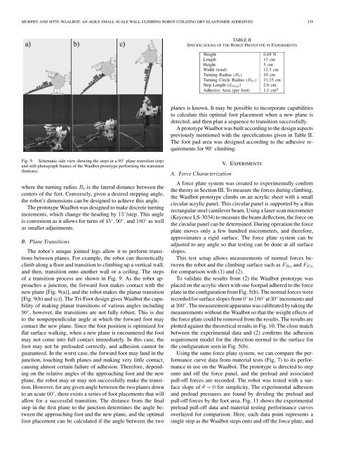
TABLE II<br />
SPECIFICATIONS OF THE ROBOT PROTOTYPE IN EXPERIMENTS<br />
planes is known. It may be possible to incorporate capabilities<br />
to calculate this optimal foot placement when a new plane is<br />
detected, and then plan a sequence to transition successfully.<br />
A prototype <strong>Waalbot</strong> was built according to the design aspects<br />
previously mentioned with the specifications given in Table II.<br />
The foot pad area was designed according to the adhesive requirements<br />
for 90 ◦ climbing.<br />
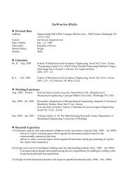
Fig. 9. Schematic side view showing the steps in a 90 ◦ plane transition (top)<br />
and still-photograph frames of the <strong>Waalbot</strong> prototype performing the transition<br />
(bottom).<br />
where the turning radius R t is the lateral distance between the<br />
centers of the feet. Conversely, given a desired stepping angle,<br />
the robot’s dimensions can be designed to achieve this angle.<br />
The prototype <strong>Waalbot</strong> was designed to make discrete turning<br />
increments, which change the heading by 15 ◦ /step. This angle<br />
is convenient as it allows for turns of 45 ◦ , 90 ◦ , and 180 ◦ as well<br />
as smaller adjustments.<br />
B. Plane Transitions<br />
The robot’s unique jointed legs allow it to perform transitions<br />
between planes. For example, the robot can theoretically<br />
climb along a floor and transition to climbing up a vertical wall,<br />
and then, transition onto another wall or a ceiling. The steps<br />
of a transition process are shown in Fig. 9. As the robot approaches<br />
a junction, the forward foot makes contact with the<br />
new plane [Fig. 9(a)], and the robot makes the planar transition<br />
[Fig. 9(b) and (c)]. The Tri-Foot design gives <strong>Waalbot</strong> the capability<br />
of making planar transitions of various angles including<br />
90 ◦ , however, the transitions are not fully robust. This is due<br />
to the nonperpendicular angle at which the forward foot may<br />
contact the new plane. Since the foot position is optimized for<br />
flat surface walking, when a new plane is encountered the foot<br />
may not come into full contact immediately. In this case, the<br />
foot may not be preloaded correctly, and adhesion cannot be<br />
guaranteed. In the worst case, the forward foot may land in the<br />
junction, touching both planes and making very little contact,<br />
causing almost certain failure of adhesion. Therefore, depending<br />
on the relative angles of the approaching foot and the new<br />
plane, the robot may or may not successfully make the transition.<br />
However, for any given angle between the two planes down<br />
to an acute 60 ◦ , there exists a series of foot placements that will<br />
allow for a successful transition. The distance from the final<br />
step in the first plane to the junction determines the angle between<br />
the approaching foot and the new plane, and the optimal<br />
foot placement can be calculated if the angle between the two<br />
V. EXPERIMENTS<br />
A. Force Characterization<br />
A force plate system was created to experimentally confirm<br />
the theory in Section III. To measure the forces during climbing,<br />
the <strong>Waalbot</strong> prototype climbs on an acrylic sheet with a small<br />
circular acrylic panel. This circular panel is supported by a thin<br />
rectangular steel cantilever beam. Using a laser scan micrometer<br />
(Keyence LS-3034) to measure the beam deflection, the force on<br />
the circular panel can be determined. During operation the force<br />
plate moves only a few hundred micrometers, and therefore,<br />
approximates a rigid surface. The force plate system can be<br />
adjusted to any angle so that testing can be done at all surface<br />
slopes.<br />
This test setup allows measurements of normal forces between<br />
the robot and the climbing surface such as F Rn and F Fn<br />
for comparison with (1) and (2).<br />
To validate the results from (2) the <strong>Waalbot</strong> prototype was<br />
placed on the acrylic sheet with one footpad adhered to the force<br />
plate in the configuration from Fig. 5(b). The normal forces were<br />
recorded for surface slopes from 0 ◦ to 180 ◦ at 30 ◦ increments and<br />
at 300 ◦ . The measurement apparatus was calibrated by taking the<br />
measurements without the <strong>Waalbot</strong> so that the weight effects of<br />
the force plate could be removed from the results. The results are<br />
plotted against the theoretical results in Fig. 10. The close match<br />
between the experimental data and (2) confirms the adhesion<br />
requirement model for the direction normal to the surface for<br />
the configuration seen in Fig. 5(b).<br />
Using the same force plate system, we can compare the performance<br />
curve data from material tests (Fig. 7) to its performance<br />
in use on the <strong>Waalbot</strong>. The prototype is directed to step<br />
onto and off the force panel, and the preload and associated<br />
pull-off forces are recorded. The robot was tested with a surface<br />
slope of θ =0for simplicity. The experimental adhesion<br />
and preload pressures are found by dividing the preload and<br />
pull-off forces by the foot area. Fig. 11 shows the experimental<br />
preload pull-off data and material testing performance curves<br />
overlayed for comparison. Here, each data point represents a<br />
single step as the <strong>Waalbot</strong> steps onto and off the force plate, and