Waalbot - NanoRobotics Lab - Carnegie Mellon University
Waalbot - NanoRobotics Lab - Carnegie Mellon University
Waalbot - NanoRobotics Lab - Carnegie Mellon University

You also want an ePaper? Increase the reach of your titles
YUMPU automatically turns print PDFs into web optimized ePapers that Google loves.
334 IEEE/ASME TRANSACTIONS ON MECHATRONICS, VOL. 12, NO. 3, JUNE 2007<br />
It can be shown that the preload converges to the intersection<br />
preload (L ∗ ) through an iterative proof using the update rule<br />
( a<br />
L i+1 = L<br />
m)<br />
( 1 n )<br />
i (6)<br />
which mathematically represents a single step, where L i is the<br />
preload for step number i. The steady-state operating preload<br />
(L ∞ ) is given by<br />
( a<br />
) A<br />
(<br />
L ∞ = lim L 1 n )<br />
n→∞<br />
0 (7)<br />
m<br />
A =1+ 1 (<br />
1+ 1 (1+ 1 ))<br />
n n n (...) = n<br />
n − 1 . (8)<br />
Therefore,<br />
( a<br />
n<br />
n −1<br />
L ∞ = = L<br />
m) ∗ . (9)<br />
The steady-state operating preload (L ∞ ) converges to the<br />
preload at the intersection of the two lines (L ∗ ) from (5). The<br />
steady-state operating adhesion (F ∞ ) is then equal to mL ∞ .<br />
These two values define a steady-state operating point, point S<br />
in Fig. 7. There is also a minimum safe adhesion value (F safe ),<br />
which is a function of the area of the footpads and the surface<br />
slope angle θ, and can be calculated from (2) and foot size. The<br />
steady state operating adhesion (F ∞ ) must be greater than the<br />
minimum safe adhesion value (F safe ) to prevent the robot from<br />
detaching from the climbing surface. The margin between the<br />
steady-state operating adhesion and the minimum safe adhesion<br />
is the margin of safety (M s ). Since the robot will not always<br />
have ideal force transfer on every step, it is important to have a<br />
large margin of safety so that the robot can recover from a problematic<br />
step, or continue to operate if the adhesives become<br />
contaminated and function with degraded performance.<br />
It is possible to increase the margin of safety by increasing<br />
the area of the adhesives (foot pad size), which lowers the<br />
minimum adhesion pressure requirement. However, there is a<br />
tradeoff because the motors then need to provide more torque to<br />
peel the larger feet. This causes an increased power requirement,<br />
which leads to larger batteries, and also necessitates a larger and<br />
heavier motor.<br />
C. Robot Fabrication<br />
A printed circuit board (PCB) acts as the chassis for the robot<br />
instead of using an additional body frame in order to keep the<br />
mass low. The leg and feet assemblies are fabricated via 3-D<br />
printing (Z-Corp. ZPrinter and 3-D Systems Invision HR). The<br />
heaviest components of the system are the leg assemblies, motors,<br />
and batteries. In order to move the center of gravity as close<br />
as possible to the surface and balanced around the motor axes, all<br />
these parts are located close to the shaft axes with the batteries<br />
beneath the PCB, nearly in contact with the climbing surface.<br />
The robot is controlled by a PIC microcontroller<br />
(PIC16F737), and is able to perform preprogrammed actions<br />
such as climbing and turning without instructions from the user.<br />
Gait is controlled with feedback from foot position sensors.<br />
Limit switches are triggered when the legs are aligned so that<br />
only one foot on each side is in contact with the surface. This<br />
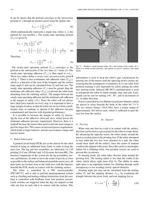
Fig. 8. <strong>Waalbot</strong>’s small turning radius (R t ) and turning circle radius (R tc )<br />
allow it to climb around obstacles, and operate in narrow corridors with sharp<br />
bends.<br />
information is used to keep the robot’s gait synchronized by<br />
pausing one of the motors until the opposing motor catches up,<br />
assuring that the assumptions of symmetry in (1) are valid. Foot<br />
position tracking is also important for safely putting the robot<br />
into steering mode. Infrared (IR) RC5 communication is used<br />
to teleoperate the robot to climb straight, stop, and turn. Commands<br />
can be sent for turning 180 ◦ , 90 ◦ , and in increments of<br />
15 ◦ in either direction.<br />
Power is provided by two lithium ion polymer batteries which<br />
are placed in series beneath the body of the robot for 7.4 V.<br />
The two motors (Sanyo 12GA-N4s) have a torque output of<br />
approximately 400 mN.m each, which is sufficient to peel the<br />
rear feet from the surface.<br />
IV. AGILITY<br />
A. Steering<br />
When only one foot on a side is in contact with the surface,<br />
that foot can be used as a pivot point for the robot to rotate about.<br />
By advancing the opposite motor, the robot rotates around the<br />
passive revolute joint in the pivoting foot. If the robot attempted<br />
to turn while the two feet were attached on a side, the robot<br />
would shear itself off the surface, since the center of rotation<br />
would not be aligned with a joint. Since this can be a catastrophic<br />
failure for a climbing robot, foot position sensors are used to<br />
prevent this occurrence.<br />
In steering mode, the robot takes discrete steps around the<br />
pivoting foot. The turning radius is less than the width of the<br />
robot, which allows tight turns (Fig. 8). The ability to make<br />
tight turns is an important feature for climbing through small<br />
passageways or for avoiding closely spaced obstacles.<br />
Steering angle per step can be calculated from the turning<br />
radius R t and the stepping distance d step by examining the<br />
triangle between the pivot, front, and rear stepping feet as<br />
( )<br />
θ =cos −1 1 − d2 step<br />
2Rt<br />
2 (10)