Waalbot - NanoRobotics Lab - Carnegie Mellon University
Waalbot - NanoRobotics Lab - Carnegie Mellon University
Waalbot - NanoRobotics Lab - Carnegie Mellon University

Create successful ePaper yourself
Turn your PDF publications into a flip-book with our unique Google optimized e-Paper software.
MURPHY AND SITTI: WAALBOT: AN AGILE SMALL-SCALE WALL-CLIMBING ROBOT UTILIZING DRY ELASTOMER ADHESIVES 331<br />
By means of compliant micro/nanoscale high-aspect-ratio<br />
beta-keratin structures on their feet, geckos and spiders manage<br />
to adhere to almost any surface with a controlled contact area<br />
[15]. It has been shown that adhesion is mainly due to molecular<br />
forces such as van der Waals forces [16] (from which <strong>Waalbot</strong><br />
draws its name). Tiny fibers on the animals’ feet form weak attractive<br />
bonds with the surface, and the combination of billions<br />
of contacting fibers creates a large adhesion (up to 100 kPa).<br />
Since dry adhesion does not rely heavily on the surface material<br />
or atmospheric pressure, it allows climbing on a wide variety of<br />
surfaces, and is uniquely suitable for use in the vacuum of space.<br />
Synthetic fibrillar dry adhesive technology is not currently<br />
mature enough to be used for climbing robots, however, <strong>Waalbot</strong><br />
is designed with the intention of eventually utilizing this<br />
technology. While efforts to develop the synthetic fibrillar dry<br />
adhesive continue [17]–[21], the robot uses polymer adhesive<br />
material (Smooth-On Vytaflex 10), which shares many performance<br />
characteristics with the envisioned dry adhesive material.<br />
Both the dry adhesive and the elastomer adhesive must be<br />
pressed to the surface with a preload force in order to provide an<br />
adhesive force on detachment. Like fiber-based biological adhesives,<br />
compliant elastomers gain their adhesion performance by<br />
deforming into the microscale surface features of any smooth<br />
surface and creating a large contact area. V10 is highly compliant<br />
with a Shore-A hardness rating of 10, and exhibits tack while<br />
leaving no residue. Using these adhesives as substitutes until the<br />
fiber-based dry adhesives have suitable performance for this application<br />
allows testing and improvements to the robot design.<br />
The adhesive elastomer is characterized for its adhesion through<br />
testing on a custom system. A sample is moved into contact with<br />
a substrate that is connected to a high-resolution load cell by an<br />
automated stage. When the pressing force reaches a specified<br />
preloading value the sample is retracted. The adhesive force is<br />
recorded as the maximum force before separation, and force<br />
values are converted to pressures by dividing the area of the<br />
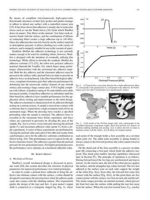
sample. Fig. 2(a) is a force versus time plot showing the preload<br />
(point P 1 ) and maximum adhesion value (point P 2 ) from a single<br />
experiment. A series of these experiments are performed by<br />
varying the preload value and a plot of the adhesion results form<br />
a performance curve for the adhesive–substrate combination as<br />
shown in Fig. 2(b). This performance curve is typical for the adhesive<br />
elastomer tested. The adhesion is greater than the preload<br />
pressure for low preload pressures. For higher preload pressures<br />
the performance curve saturates at a maximum adhesion value.<br />
III. ROBOT DESIGN<br />
A. Mechanical Design<br />
<strong>Waalbot</strong>’s overall mechanical design is discussed in previous<br />
work [20]; this section describes the selection of physical<br />
parameters for improved performance over initial prototypes.<br />
In order to create a preload force sufficient to bring the adhesive<br />
into intimate contact with the surface, a robot should be<br />
designed to maximize the pressing force when the adhesive pads<br />
come into contact with the climbing surface. This requirement<br />
guides the design of the legs and feet. A gear motor’s output<br />
shaft is connected to a triangular shaped leg (Fig. 3), where<br />
Fig. 2. (a) Typical force versus time data plot for a single adhesion test where<br />
P 1 corresponds to the preload and P 2 corresponds to the adhesion. (b) Performance<br />
curve for a flat V10 elastomer on a smooth acrylic surface.<br />
Fig. 3. CAD model of the Tri-Foot design (left) and a photograph of the<br />
assembled prototype components (right). Each foot pad has two degrees of<br />
freedom enabling climbing and steering. Axis A allows the foot to rotate to<br />
maintain contact with the surface. Axis B allows for footpad rotation.<br />
each point of the triangle holds a foot assembly on a revolute<br />
ankle joint (A). The ankle joint assembly is spring loaded to<br />
always return to the forward position (the robot cannot travel in<br />
reverse).<br />
On the distal end of the foot assembly is a passive revolute<br />
joint (B) connecting a foot pad, which holds the adhesive material.<br />
This distal joint enables steering capabilities (discussed<br />
later in Section IV). The principle of operation is as follows.<br />
During forward travel the two legs are synchronized and step in<br />
unison. As the motors turn, the tail of the robot presses against<br />
the surface, and the triangular legs rotate forward. The two feet<br />
adhered to the surface (one on each side) support the weight<br />
of the robot [Fig. 4(a)]. Soon after, the forward feet come into<br />
contact with the surface [Fig. 4(b)]. At this point there are five<br />
contact points with the surface: two feet on each side and the tail.<br />
The motor torque provides an internal moment, which presses<br />
the front feet onto the surface while pulling the rear feet away<br />
from the surface. When the rear foot normal force F Rn reaches