View - NanoRobotics Lab - Carnegie Mellon University
View - NanoRobotics Lab - Carnegie Mellon University
View - NanoRobotics Lab - Carnegie Mellon University

Create successful ePaper yourself
Turn your PDF publications into a flip-book with our unique Google optimized e-Paper software.
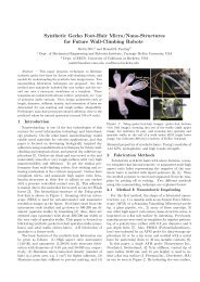
Biologically Inspired Polymer Microfibers with<br />
Spatulate Tips as Repeatable Fibrillar Adhesives<br />
Seok Kim and Metin Sitti *<br />
<strong>NanoRobotics</strong> <strong>Lab</strong>oratory, Department of Mechanical Engineering,<br />
<strong>Carnegie</strong> <strong>Mellon</strong> <strong>University</strong>, Pittsburgh, PA 15213, USA<br />
ABSTRACT. Being inspired by gecko foot-hairs, microfibers with flat spatulate tips are<br />
proposed as repeatable adhesives. They are fabricated by molding a master template<br />
fabricated using deep reactive ion etching and the notching effect. Fabricated<br />
polyurethane fiber arrays with 4.5 μm fiber and 9 μm tip diameter demonstrated<br />
macroscale adhesion pressures up to 18 N/cm 2 and overall work of adhesion up to 11<br />
J/m 2 on a 6 mm diameter glass hemisphere for a preload pressure of 12 N/cm 2 . These<br />
results show around 4 times higher adhesion and 5 times higher overall work of adhesion<br />
with compared to the flat polyurethane surface.<br />
KEYWORDS. Fibrillar adhesives, microscale contact mechanics, compliant<br />
microstructures, biological adhesion.<br />
* E-Mail: sitti@cmu.edu<br />
1
Geckos are exceptional in their ability to climb up smooth vertical surfaces because<br />
their hierarchical micro/nanoscale foot-hairs with their spatulate tips can attach to almost<br />
any smooth or micro/nanoscale rough surface repeatedly with a controllable adhesion<br />
pressure up to around 10 N/cm 2 (100 kPa) 1 . Recent findings have shown that van der<br />
Waals and possibly capillary forces play a dominant role in their fibrillar adhesion 1-4 .<br />
Many adhesion and contact mechanics models for the microfibrillar interfaces have been<br />
developed 5-10<br />
and synthetic fibrillar adhesives have been attempted to be fabricated.<br />
Fabrication methods for recent micro/nanoscale synthetic dry adhesives consist of<br />
electron-beam lithography 11 , replication of templates using molding or casting 12 ,<br />
drawing 13 , printing 14 , growing 18 , and more complex microfabrication combined with selfassembly<br />
15 . These works focused on fabricating micro/nanoscale high aspect ratio and<br />
high density polymer or carbon nanotube fibers on a flat substrate. However, these<br />
methods can not fabricate spatulate tips at the end of these fibers.<br />
Flat and larger diameter spatulate tips are postulated to enhance the adhesion and<br />
work of adhesion significantly due to the increased tip contact area at the fiber-surface<br />
interface 5 . In order to model the work of adhesion enhancement approximately, a single<br />
polymer fiber is assumed to be stretched while its volume is conserved. In addition, if<br />
pull-off of each fiber tip is assumed to happen simultaneously where overall pull-off<br />
force per unit area is a constant value (<br />
c 1<br />
) and the elastic deformation is assumed to<br />
happen at the fiber stem only where the polymer Young’s modulus ( E ) is assumed to be<br />
constant. Then, the maximum stretched length (<br />
single fiber during separation can be computed as<br />
x c<br />
) and work of adhesion (W ) of a<br />
2
x c<br />
2<br />
Ed0<br />
= x<br />
(1)<br />
0<br />
2<br />
Ed − c D<br />
2<br />
0<br />
1<br />
W<br />
x c<br />
2<br />
2<br />
2<br />
d ⎡<br />
⎤<br />
0<br />
x0<br />
c1D<br />
Ed0<br />
= ∫ Fdx = π E ⎢ − ln<br />
2 2<br />
2 2 ⎥ (2)<br />
4 ⎣ Ed0<br />
− c1D<br />
Ed0<br />
− c1D<br />
x<br />
⎦<br />
0<br />
where is the initial stem length, D is the fiber spatulate tip diameter, and d is the<br />
x0<br />
0<br />
fiber stem diameter. From (1) and (2), elastomer fibers with larger diameter tips elongate<br />
and dissipate energy significantly, and thus the work of adhesion per fiber is increased.<br />
Moreover, adhesion is also increased by a fiber array with larger flat spatulate tips since:<br />
(1) The fracture mechanics of the microfibers is flaw insensitive<br />
19 (the stress at the<br />
interface is uniform and equal to the intrinsic adhesion strength at the instant of pull-off)<br />
and thus enables the maximum possible adhesion pressure; (2) Flat and compliant<br />
spatulate tips enable easier contact to a smooth surface with almost no alignment<br />
problem; (3) Fiber stretching enables larger number of fibers staying in contact with a<br />
smooth surface during pull-off. Therefore, this paper is focused on fabrication of polymer<br />
microfibers with flat and larger spatulate tips for fibrillar adhesives with improved<br />
adhesion capability.<br />
The fabrication process of polymer microfibers with flat and larger diameter<br />
spatulate tips is explained in Fig. 1. A silicon-on-insulator (SOI) wafer (Addison<br />
Engineering) is used as a substrate which has 20 μm thick top silicon layer and 0.5 μm<br />
thick SiO 2 layer. After the optical lithography step in Fig. 1(a), the negative fiber array<br />
template is formed in Fig. 1(b). The required fiber profile shape is obtained in two steps.<br />
At first, isotropic etching is used for forming the circular supporting shape of the base of<br />
each fiber to reduce the stress concentration for preventing the fracture of fibers at their<br />
bases. Next, deep reactive ion etching (DRIE) is followed for forming vertical high<br />
3
aspect ratio microchannels. Isotropic etching and DRIE were carried out consecutively in<br />
STS ® Multiplex ICP RIE with 20 mT pressure, 130 sccm SF 6 , 20 sccm O 2 , 600 W coil<br />
power, and 120 W platen power. When the vertical etching reaches to the silicon oxide<br />
layer, it can not proceed vertically any more and then starts to expand laterally on the<br />
oxide interface. This effect is called the notching effect 17 . By controlling the lateral<br />
etching time, spatulate tip diameter is determined. Then, in Fig. 1(c), the template is<br />
filled with a liquid polymer under vacuum to remove not only the trapped air but also the<br />
native gas in the liquid polymer, and then the polymer is cured. Here, any polymer (e.g.<br />
Parylene ® C) or any other fiber material can be also gas phase deposited inside to the<br />
template. In Fig. 1(d), the polymer fiber array with a backing layer is released by three<br />
step etching: At first, the bottom silicon layer is etched away by XeF 2 dry etching; Thin<br />
oxide layer is removed by buffered oxide etching (BOE); Finally, the 20 μm thick top<br />
silicon layer is etched away by XeF 2 etching in around 30 minutes to release the fibers<br />
with a backing layer. Here, the final etching step is critical. Since using a wet etching<br />
technique such as KOH etching would result in clumped fibers due to capillary forces<br />
during drying, XeF 2 dry etching is used to prevent any clumping issues. Moreover, since<br />
the DRIE process natively creates Teflon® like thin submicron film on the template<br />
microchannel side walls during the process 16 , each released polymer fiber is expected to<br />
be coated with this hydrophobic thin film on their side walls (not at the spatulate tip<br />
surface). This very low surface energy coating could reduce the cohesion of microfibers<br />
significantly, and thus it could minimize any clumping during the mechanical contact of<br />
neighboring fibers.<br />
4
Besides forming the flat spatulate tips, above fabrication process has other<br />
advantages with respect to previous fibrillar adhesive fabrication methods: (1) Fiber<br />
material can be fabricated from any polymer which can be in a liquid solution form or<br />
can be gas phase deposited; (2) Array of fibers can be fabricated in large areas up to 8<br />
inch wafer size cost effectively using a single mask; (3) The yield is almost 100%; (4)<br />
This method can be extended to the fabrication of 100s of nanometer diameter fibers by<br />
using a higher resolution lithography step in Fig. 1(a), e.g. using phase masks. As the<br />
only drawback of this and all other previous methods, only vertical fibers can be<br />
fabricated while the biological foot-hairs mostly have an angle which enables an<br />
anisotropic friction property for the hairs 14 . Fabrication of angled microfibers with<br />
spatulate tips is a future work.<br />
High tensile strength elastomer polyurethane (ST-1060, BJB Enterprise) with<br />
Young’s modulus of around 3 MPa was selected as the fiber adhesive material. Scanning<br />
electron microscope (SEM) (Hitachi 2460N) image of the resulting microfiber array with<br />
4.5 μm fiber diameter, 9 μm tip diameter, 4.5 μm base supporter diameter, 20 μm length,<br />
and 12 μm spacing between each fiber center (44% fiber tip area density) is displayed in<br />
Fig 2. These geometries are held by 80 sec isotropic etching for the fiber base supporter<br />
structures and by 21 min 20 sec vertical etching for the fiber and spatulate tips.<br />
Performance of a fibrillar adhesive is characterized by its macroscale adhesion (P)<br />
and overall work of adhesion (W). To characterize these parameters for the fabricated<br />
fiber arrays during adhering to a glass hemisphere, a custom tensile macroscale adhesion<br />
measurement setup was built. Here, a glass hemisphere instead of a flat glass surface is<br />
selected as the test surface in order to have no alignment errors during the measurements.<br />
5
A 6 mm diameter very smooth glass hemisphere (ISP Optics, QU-HS-6) attached to a<br />
load cell (Transducer Techniques, GSO-25) was moved vertically by a motorized stage<br />
(Newport, MFA-CC) with 100 nm resolution. The hemisphere was contacted to and<br />
retracted from the fiber array sample with a pre-specified preload force and a very slow<br />
speed (1 μm/s) to minimize any viscoelastic effects. The maximum tensile force during<br />
the glass hemisphere and fiber array separation (pull-off force) gave the adhesion, and the<br />
hysteresis area between the loading and unloading curves gave the dissipated energy<br />
between the loading and unloading of the fiber array. Dividing this dissipated energy by<br />
the maximum circular contact area during loading gave W 10 . During the force<br />
measurements, an inverted microscope (Nikon Eclipse TE200) is used to measure the real<br />
circular maximum contact area between the hemisphere and the fiber array.<br />
Adhesion and overall work of adhesion of 15x15 mm 2 area and 1 mm thick ST-<br />
1060 polyurethane fiber array samples and a 1 mm thick flat and smooth ST-1060 surface<br />
were measured on the glass hemisphere using the above setup. Here, the flat<br />
polyurethane surface was used as a control substrate to show the relative enhancement of<br />
P and W by structuring the same material as a cylindrical microfiber with flat spatulate<br />
tips. Since ST-1060 is also etched slightly during the final XeF 2 dry etching step in Fig<br />
1(d), flat sample was also exposed to XeF 2 for about 30 minutes to have the same surface<br />
roughness with the flat spatulate tip surface.<br />
Using the above setup, the fiber array and the glass hemisphere interface adhesion<br />
and overall work of adhesion are measured as shown in Fig. 3. Plots show the error bars<br />
measured from the force-distance data at two different locations on the fiber array for<br />
preloads up to 25 mN. Adhesion values saturate as preload increases, and the array of<br />
6
fibers has around 4 times higher adhesion than the flat surface. Dividing the adhesion to<br />
the optically measured maximum circular contact area during loading, maximum<br />
adhesion pressure for the fiber array can be computed as 18 N/cm 2 at a preload pressure<br />
of 12 N/cm 2 . Overall work of adhesion of the fibers is 5 times higher than the one from<br />
the flat elastomer surface. This energy dissipation enhancement is due to the lost energy<br />
during separating the elastic and highly stretched fibers from the adhered glass surface as<br />
given in (2). ST-1060 fibers stretched up to 500% strain in the experiments (observed by<br />
profile view optical imaging) which would show the reason of the enhancement of the<br />
elastic energy loss during unloading the fibers.<br />
Macroscale adhesion data from the fiber array in this work are compared with the<br />
previous works as given in Table 1. The polymer fibers with spatulate tips show better<br />
adhesion pressure than other synthetic gecko inspired fibrillar adhesives with no spatulate<br />
tips although the single fiber in this work is over 20 times thicker than the single fibers<br />
which are fabricated in other works. In order to even increase the adhesion performance<br />
in this work, microfibers with tips will be scaled down to 100s of nanometers in diameter<br />
using phase mask type of sub-micron lithography techniques. Here,<br />
N<br />
times self-similar<br />
scaling down in fiber diameter will generate<br />
N times higher adhesion 20 , and smaller<br />
fibers will need less preload than larger fibers to obtain the same adhesion.<br />
In conclusion, polyurethane elastomer microfiber arrays with flat spatulate tips<br />
are proposed as biologically inspired repeatable fibrillar adhesives in this work. For a<br />
preload pressure of around 12 N/cm 2 , adhesion pressures up to 18 N/cm 2 and overall<br />
work of adhesion up to 11 J/m 2 are demonstrated for polyurethane fibers with 4.5 μm<br />
fiber diameter, 9 μm tip diameter, 20 μm length, and 44% fiber tip area density on a 6<br />
7
mm diameter glass hemisphere. These repeatable fibrillar adhesives would have wide<br />
range of applications as space, biomedical, sports, etc. adhesives.<br />
8
REFERENCES<br />
1 K. Autumn, Y. A. Liang, S. T. Hsieh, W. Zesch, W. P. Chan, T. W. Kenny, R. Fearing,<br />
and R. J. Full, Nature, 405, 681 (2000)<br />
2 K. Autumn, M. Sitti, Y. A. Liang, A. M. Peattie, W. R. Hansen, S. Sponberg, T. W.<br />
Kenny, R. Fearing, J. N. Israelachvili, and R. J. Full, PNAS, 99, 12252 (2002)<br />
3 G. Huber, H. Mantz, R. Spolenak, K. Mecke, K. Jacobs, S. N. Grob, and E. Artz, PNAS,<br />
102(45), 16293 (2005)<br />
4 G. Huber, S. N. Grob, R. Spolenak, and E Artz, Biology Letters, 1, 2 (2005)<br />
5 H. Gao and H. Yao, PNAS, 101, 7851 (2004)<br />
6 T. Tang, C. Hui, and N. J. Glassmaker, J. Roy. Soc. Interface, 2, 505 (2005)<br />
7 N. J. Glassmaker, A. Jagota, C. Hui, and J. Kim, J. Roy. Soc. Interface, 1, 1 (2004)<br />
8 C. Hui, N. J. Glassmaker, T. Tang, and A. Jagota, J. Roy. Soc. Interface, 1, 35 (2004)<br />
9 B. N. J. Persson, J. Chemical Physics, 118, 7614 (2003)<br />
10 A. J. Crosby, M. Hageman, and A. Duncan, Langmuir, 21, 11738 (2005)<br />
11 A. K. Geim, S. V. Dubnos, I. V. Grigorieva, K. S. Novoselov, A. A. Zhukov, and S. Y.<br />
Shapoval, Nature Materials, 2, 461 (2003)<br />
12 D. Campolo, S. Jones, and R. S. Fearing, Proc. of the IEEE Nanotechnology Conf., 12<br />
(2003)<br />
13 H. E. Jeong, S. H. Lee, P. Kim, and K. Y. Suh, Nano Letters, 6, 1508 (2004)<br />
14 M. Sitti and R. S. Fearing, J. Adhesion Science and Technology, 17(5), 1055 (2003)<br />
15 M. T. Northen and K. L. Turner, Nanotechnology, 16, 1159 (2005)<br />
16 A. A. Ayon, R. Braff, C. C. Lin, H. H. Sawin, and M. A. Schmidt, J. of<br />
Electrochemical Society, 146(1), 339 (1999)<br />
9
17 M. E. McNie, D. O. King, V. Nayar, M. C. L. Ward, J. S. Burdess, C. Quinn, and S.<br />
Blackstone, Proc. of IEEE International SOI Conference, 60 (1997)<br />
18 Y. Zhao, T. Tong, L. Delzeit, A. Kashani, M. Meyyappan, and A. Majumdar, J. Vac.<br />
Sci. Techno. B, 24(1), 331 (2006)<br />
19<br />
M. Murphy, B. Aksak, and M. Sitti, Langmuir, under review (2006)<br />
20 E. Arzt, S. Gorb, and R. Spolenak, PNAS, 100, 10603 (2003)<br />
10
TABLE CAPTIONS<br />
Table 1. Comparison of adhesive strength among various natural and synthetic gecko<br />
inspired micro/nanofibers 18 .<br />
11
FIGURE CAPTIONS<br />
FIG. 1. Schematic process flow steps for the fabrication of polymer microfiber arrays<br />
with flat spatulate tips: (a) An SOI wafer top surface is patterned using optical<br />
lithography; (b) Negative fiber array template is formed using a two-step deep reactive<br />
ion etching process; (c) The template is filled with a liquid polymer under vacuum and<br />
the polymer is cured, or it is filled by gas phase deposition of a polymer; (d) Polymer<br />
fiber arrays with spatulate tips and a backing layer are released.<br />
FIG. 2. SEM image of the isometric view of a polyurethane elastomer microfiber array<br />
with 4.5 μm fiber diameter, 9 μm tip diameter, 20 μm length, and 44% fiber density<br />
(Scale bar: 50 μm).<br />
FIG. 3. Macroscale adhesion (upper plot) and overall work of adhesion (lower plot) of<br />
polyurethane microfibers and flat polyurethane flat control surface on a 6 mm diameter<br />
glass hemisphere for varying preloads.<br />
12