Assembly and Disassembly of Magnetic Mobile Micro-Robots ...
Assembly and Disassembly of Magnetic Mobile Micro-Robots ...
Assembly and Disassembly of Magnetic Mobile Micro-Robots ...

You also want an ePaper? Increase the reach of your titles
YUMPU automatically turns print PDFs into web optimized ePapers that Google loves.
y<br />
z<br />
H m<br />
x<br />
M1<br />
T ec +T i<br />
m 1<br />
L m<br />
F s,i<br />
W b<br />
F ec + F i<br />
m 2<br />
M2<br />
P c1<br />
c o<br />
Surface<br />
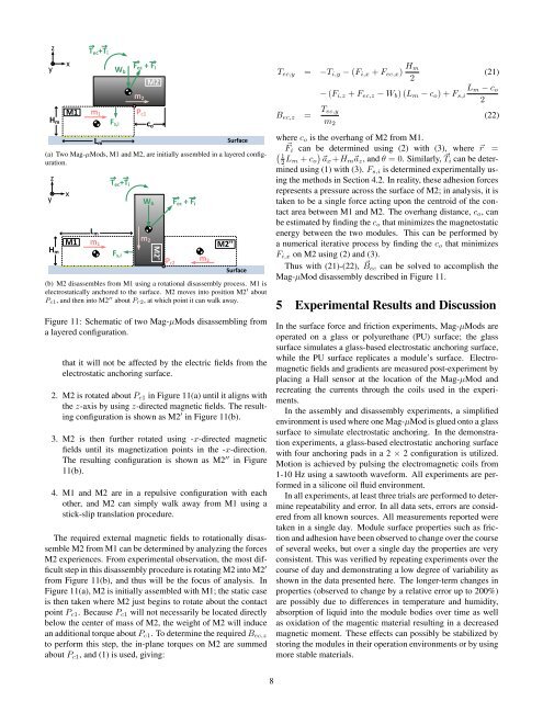
(a) Two Mag-µMods, M1 <strong>and</strong> M2, are initially assembled in a layered configuration.<br />
y<br />
z<br />
x<br />
L m<br />
m 1<br />
T ec +T i<br />
W b<br />
M1<br />
m 2<br />
H m<br />
F s,i<br />
M2'<br />
F ec + F i<br />
P r2<br />
m 2<br />
M2''<br />
Surface<br />
(b) M2 disassembles from M1 using a rotational disassembly process. M1 is<br />
electrostatically anchored to the surface. M2 moves into position M2 ′ about<br />
P c1 , <strong>and</strong> then into M2 ′′ about P r2 , at which point it can walk away.<br />
Figure 11: Schematic <strong>of</strong> two Mag-µMods disassembling from<br />
a layered configuration.<br />
that it will not be affected by the electric fields from the<br />
electrostatic anchoring surface.<br />
2. M2 is rotated about P c1 in Figure 11(a) until it aligns with<br />
the z-axis by using z-directed magnetic fields. The resulting<br />
configuration is shown as M2 ′ in Figure 11(b).<br />
3. M2 is then further rotated using -x-directed magnetic<br />
fields until its magnetization points in the -x-direction.<br />
The resulting configuration is shown as M2 ′′ in Figure<br />
11(b).<br />
4. M1 <strong>and</strong> M2 are in a repulsive configuration with each<br />
other, <strong>and</strong> M2 can simply walk away from M1 using a<br />
stick-slip translation procedure.<br />
The required external magnetic fields to rotationally disassemble<br />
M2 from M1 can be determined by analyzing the forces<br />
M2 experiences. From experimental observation, the most difficult<br />
step in this disassembly procedure is rotating M2 into M2 ′<br />
from Figure 11(b), <strong>and</strong> thus will be the focus <strong>of</strong> analysis. In<br />
Figure 11(a), M2 is initially assembled with M1; the static case<br />
is then taken where M2 just begins to rotate about the contact<br />
point P c1 . Because P c1 will not necessarily be located directly<br />
below the center <strong>of</strong> mass <strong>of</strong> M2, the weight <strong>of</strong> M2 will induce<br />
an additional torque about P c1 . To determine the required B ec,z<br />
to perform this step, the in-plane torques on M2 are summed<br />
about P c1 , <strong>and</strong> (1) is used, giving:<br />
T ec,y = −T i,y − (F i,x + F ec,x ) H m<br />
2<br />
(21)<br />
− (F i,z + F ec,z − W b ) (L m − c o ) + F s,i<br />
L m − c o<br />
2<br />
B ec,z = T ec,y<br />
m 2<br />
(22)<br />
where c o is the overhang <strong>of</strong> M2 from M1.<br />
⃗F i can be determined using (2) with (3), where ⃗r =<br />
( 1<br />
2 L m + c o<br />
)<br />
⃗ax +H m ⃗a z , <strong>and</strong> θ = 0. Similarly, ⃗ T i can be determined<br />
using (1) with (3). F s,i is determined experimentally using<br />
the methods in Section 4.2. In reality, these adhesion forces<br />
represents a pressure across the surface <strong>of</strong> M2; in analysis, it is<br />
taken to be a single force acting upon the centroid <strong>of</strong> the contact<br />
area between M1 <strong>and</strong> M2. The overhang distance, c o , can<br />
be estimated by finding the c o that minimizes the magnetostatic<br />
energy between the two modules. This can be performed by<br />
a numerical iterative process by finding the c o that minimizes<br />
F i,x on M2 using (2) <strong>and</strong> (3).<br />
Thus with (21)-(22), ⃗ Bec can be solved to accomplish the<br />
Mag-µMod disassembly described in Figure 11.<br />
5 Experimental Results <strong>and</strong> Discussion<br />
In the surface force <strong>and</strong> friction experiments, Mag-µMods are<br />
operated on a glass or polyurethane (PU) surface; the glass<br />
surface simulates a glass-based electrostatic anchoring surface,<br />
while the PU surface replicates a module’s surface. Electromagnetic<br />
fields <strong>and</strong> gradients are measured post-experiment by<br />
placing a Hall sensor at the location <strong>of</strong> the Mag-µMod <strong>and</strong><br />
recreating the currents through the coils used in the experiments.<br />
In the assembly <strong>and</strong> disassembly experiments, a simplified<br />
environment is used where one Mag-µMod is glued onto a glass<br />
surface to simulate electrostatic anchoring. In the demonstration<br />
experiments, a glass-based electrostatic anchoring surface<br />
with four anchoring pads in a 2 × 2 configuration is utilized.<br />
Motion is achieved by pulsing the electromagnetic coils from<br />
1-10 Hz using a sawtooth waveform. All experiments are performed<br />
in a silicone oil fluid environment.<br />
In all experiments, at least three trials are performed to determine<br />
repeatability <strong>and</strong> error. In all data sets, errors are considered<br />
from all known sources. All measurements reported were<br />
taken in a single day. Module surface properties such as friction<br />
<strong>and</strong> adhesion have been observed to change over the course<br />
<strong>of</strong> several weeks, but over a single day the properties are very<br />
consistent. This was verified by repeating experiments over the<br />
course <strong>of</strong> day <strong>and</strong> demonstrating a low degree <strong>of</strong> variability as<br />
shown in the data presented here. The longer-term changes in<br />
properties (observed to change by a relative error up to 200%)<br />
are possibly due to differences in temperature <strong>and</strong> humidity,<br />
absorption <strong>of</strong> liquid into the module bodies over time as well<br />
as oxidation <strong>of</strong> the magentic material resulting in a decreased<br />
magnetic moment. These effects can possibly be stabilized by<br />
storing the modules in their operation environments or by using<br />
more stable materials.<br />
8