Assembly and Disassembly of Magnetic Mobile Micro-Robots ...
Assembly and Disassembly of Magnetic Mobile Micro-Robots ...
Assembly and Disassembly of Magnetic Mobile Micro-Robots ...

Create successful ePaper yourself
Turn your PDF publications into a flip-book with our unique Google optimized e-Paper software.
70<br />
60<br />
Experiment<br />
Simulation<br />
Simulation µ i<br />
=0<br />
7<br />
6<br />
Experiment<br />
Simulation<br />
50<br />
5<br />
B ec,z<br />
(mT)<br />
40<br />
30<br />
B ec,z<br />
(mT)<br />
4<br />
3<br />
20<br />
2<br />
10<br />
1<br />
0<br />
MR1 MR2 MR3 MR4 MR5 MR6<br />
Module Species #<br />
0<br />
MR1 MR2 MR3<br />
Module Species #<br />
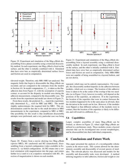
Figure 19: Experiment <strong>and</strong> simulation <strong>of</strong> the Mag-µMods disassembling<br />
from a planar assembly using a rotational disassembly<br />
method. In each experiment, one Mag-µMod is fixed on the<br />
surface, <strong>and</strong> the other is initially combined with it. Simulated<br />
data have error bars as empirically determined surface forces<br />
<strong>and</strong> friction are used in computation.<br />
tilevered weight. Therefore, only MR1-MR3 are analyzed. The<br />
magnetic fields that begin to disassemble the Mag-µMods are<br />
recorded, <strong>and</strong> are compared to the estimates from the models<br />
in Section 4.6. In model computations, F s,i is taken as the flatadhesion<br />
data from Figure 13, with the assumption <strong>of</strong> asperity<br />
contact, to account for the disparity in module area during the<br />
adhesion measurement, compared to the disassembly case. The<br />
results from the experiment <strong>and</strong> model are shown in Figure 21.<br />
From these results, the predicted B ec,z match the experimentally<br />
determined B ec,z well for MR1 <strong>and</strong> MR2. The model<br />
slightly underestimates the required field for MR3. This underestimation<br />
could be due due to the small deviation in MR3<br />
measurements in the experiment, compared to MR1 or MR2.<br />
One possibility for this result is that insufficient disassembly<br />
attempts were performed, <strong>and</strong> a very particular case was being<br />
Figure 20: Frames from a movie showing two Mag-µMods<br />
(species MR2), M1 (anchored) <strong>and</strong> M2 (unanchored), disassembling<br />
from a layered configuration (video available in Extension<br />
2). (a) Initial configuration. (b) M2 rotates into a vertical<br />
orientation with magnetization into the page, <strong>and</strong> rotates<br />
further in (c) until it is in a repulsive orientation with M1. Direction<br />
<strong>of</strong> magnetization is shown on each module.<br />
Figure 21: Experiment <strong>and</strong> simulation <strong>of</strong> the Mag-µMods disassembling<br />
from a layered assembly using a rotational disassembly<br />
method. In each experiment, one Mag-µMod is fixed<br />
on the surface, <strong>and</strong> the other is initially combined with it. Simulated<br />
data have error bars as empirically determined surface<br />
forces <strong>and</strong> friction are used in computation. Only MR4-MR6<br />
were not capable <strong>of</strong> being assembled in a layered fashion, <strong>and</strong><br />
are not shown.<br />
repeated, which may not be entirely representative. For example,<br />
this disassembly method depends on the adhesion between<br />
modules, which acts as a torque. The location <strong>of</strong> this adhesive<br />
force is taken to be at the center <strong>of</strong> the overlap <strong>of</strong> the two modules<br />
(as in Figure 11(a)), however in reality, will depend on the<br />
positions <strong>of</strong> the asperities, an unknown. If in the experiment,<br />
the location <strong>of</strong> the asperities that were in contact between the<br />
two modules happened to be in the same place in all trials, then<br />
the deviation in the result can be low. However, if the modules<br />
were flipped so that different surfaces <strong>of</strong> the modules were in<br />
contact, then the location <strong>of</strong> the asperities is likely to be different,<br />
<strong>and</strong> will result in a different B ec,z .<br />
5.6 Capabilities<br />
Larger, complex assemblies <strong>of</strong> many Mag-µMods can be<br />
formed, as shown in Figure 22, where eight Mag-µMods are<br />
utilized in a preliminary study. These modules create a layered<br />
structure that can be reconfigured into several morphologies,<br />
<strong>and</strong> be disassembled into their individual components.<br />
6 Conclusions <strong>and</strong> Future Work<br />
This paper presented the analysis <strong>of</strong> a reconfigurable robotic<br />
system at the micro-scale. This system allowed for the deterministic<br />
assembly <strong>and</strong> disassembly <strong>of</strong> several species <strong>of</strong> modules.<br />
The relevant physics was discussed <strong>and</strong> models for the<br />
assembly <strong>and</strong> disassembly tasks were developed. A method<br />
utilizing magnetics to infer adhesion, friction <strong>and</strong> weight in-situ<br />
12