Assembly and Disassembly of Magnetic Mobile Micro-Robots ...
Assembly and Disassembly of Magnetic Mobile Micro-Robots ...
Assembly and Disassembly of Magnetic Mobile Micro-Robots ...

Create successful ePaper yourself
Turn your PDF publications into a flip-book with our unique Google optimized e-Paper software.
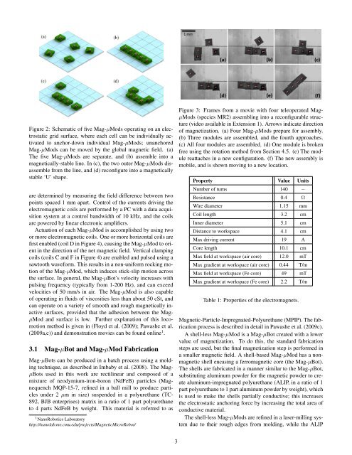
Figure 2: Schematic <strong>of</strong> five Mag-µMods operating on an electrostatic<br />
grid surface, where each cell can be individually activated<br />
to anchor-down individual Mag-µMods; unanchored<br />
Mag-µMods can be moved by the global magnetic field. (a)<br />
The five Mag-µMods are separate, <strong>and</strong> (b) assemble into a<br />
magnetically-stable line. In (c), the two outer Mag-µMods disassemble<br />
from the line, <strong>and</strong> (d) reconfigure into a magnetically<br />
stable ‘U’ shape.<br />
are determined by measuring the field difference between two<br />
points spaced 1 mm apart. Control <strong>of</strong> the currents driving the<br />
electromagnetic coils are performed by a PC with a data acquisition<br />
system at a control b<strong>and</strong>width <strong>of</strong> 10 kHz, <strong>and</strong> the coils<br />
are powered by linear electronic amplifiers.<br />
Actuation <strong>of</strong> each Mag-µMod is accomplished by using two<br />
or more electromagnetic coils. One or more horizontal coils are<br />
first enabled (coil D in Figure 4), causing the Mag-µMod to orient<br />
in the direction <strong>of</strong> the net magnetic field. Vertical clamping<br />
coils (coils C <strong>and</strong> F in Figure 4) are enabled <strong>and</strong> pulsed using a<br />
sawtooth waveform. This results in a non-uniform rocking motion<br />
<strong>of</strong> the Mag-µMod, which induces stick-slip motion across<br />
the surface. In general, the Mag-µBot’s velocity increases with<br />
pulsing frequency (typically from 1-200 Hz), <strong>and</strong> can exceed<br />
velocities <strong>of</strong> 50 mm/s in air. The Mag-µMod is also capable<br />
<strong>of</strong> operating in fluids <strong>of</strong> viscosities less than about 50 cSt, <strong>and</strong><br />
can operate on a variety <strong>of</strong> smooth <strong>and</strong> rough magnetically inactive<br />
surfaces, provided that the adhesion between the Mag-<br />
µMod <strong>and</strong> surface is low. Further explanation <strong>of</strong> this locomotion<br />
method is given in (Floyd et al. (2009); Pawashe et al.<br />
(2009a,c)) <strong>and</strong> demonstration movies can be found online 1 .<br />
3.1 Mag-µBot <strong>and</strong> Mag-µMod Fabrication<br />
Mag-µBots can be produced in a batch process using a molding<br />
technique, as described in Imbaby et al. (2008). The Mag-<br />
µBots used in this work are rectilinear <strong>and</strong> composed <strong>of</strong> a<br />
mixture <strong>of</strong> neodymium-iron-boron (NdFeB) particles (Magnequench<br />
MQP-15-7, refined in a ball mill to produce particles<br />
under 2 µm in size) suspended in a polyurethane (TC-<br />
892, BJB enterprises) matrix in a ratio <strong>of</strong> 1 part polyurethane<br />
to 4 parts NdFeB by weight. This material is referred to as<br />
1 NanoRobotics Laboratory<br />
http://nanolab.me.cmu.edu/projects/<strong>Magnetic</strong><strong>Micro</strong>Robot/<br />
Figure 3: Frames from a movie with four teleoperated Mag-<br />
µMods (species MR2) assembling into a reconfigurable structure<br />
(video available in Extension 1). Arrows indicate direction<br />
<strong>of</strong> magnetization. (a) Four Mag-µMods prepare for assembly.<br />
(b) Three modules are assembled, <strong>and</strong> the fourth approaches.<br />
(c) All four modules are assembled. (d) One module is broken<br />
free using the rotation method from Section 4.5. (e) The module<br />
reattaches in a new configuration. (f) The new assembly is<br />
mobile, <strong>and</strong> is shown moving to a new location.<br />
Property Value Units<br />
Number <strong>of</strong> turns 140 −<br />
Resistance 0.4 Ω<br />
Wire diameter 1.15 mm<br />
Coil length 3.2 cm<br />
Inner diameter 5.1 cm<br />
Distance to workspace 4.1 cm<br />
Max driving current 19 A<br />
Core length 10.1 cm<br />
Max field at workspace (air core) 12.0 mT<br />
Max gradient at workspace (air core) 0.44 T/m<br />
Max field at workspace (Fe core) 49 mT<br />
Max gradient at workspace (Fe core) 2.2 T/m<br />
Table 1: Properties <strong>of</strong> the electromagnets.<br />
<strong>Magnetic</strong>-Particle-Impregnated-Polyurethane (MPIP). The fabrication<br />
process is described in detail in Pawashe et al. (2009c).<br />
A shell-less Mag-µMod is a Mag-µBot created with a lower<br />
value <strong>of</strong> magnetization. To do this, the st<strong>and</strong>ard fabrication<br />
steps are used, but the final magnetization step is performed in<br />
a smaller magnetic field. A shell-based Mag-µMod has a nonmagnetic<br />
shell encasing a ferromagnetic core (the Mag-µBot).<br />
The shells are fabricated in a manner similar to the Mag-µBot,<br />
substituting aluminum powder for the magnetic powder to create<br />
aluminum-impregnated polyurethane (ALIP, in a ratio <strong>of</strong> 1<br />
part polyurethane to 1 part aluminum powder by weight), which<br />
is used to make the shells partially conductive; this increases<br />
the electrostatic anchoring force by increasing the total area <strong>of</strong><br />
conductive material.<br />
The shell-less Mag-µMods are refined in a laser-milling system<br />
due to their rough edges from molding, while the ALIP<br />
3