an orthotropic continuum model for the analysis of masonry structures
an orthotropic continuum model for the analysis of masonry structures
an orthotropic continuum model for the analysis of masonry structures

Create successful ePaper yourself
Turn your PDF publications into a flip-book with our unique Google optimized e-Paper software.
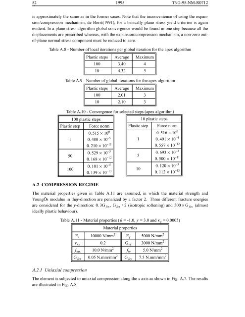
52 1995 TNO-95-NM-R0712is approximately <strong>the</strong> same as in <strong>the</strong> <strong>for</strong>mer cases. Note that <strong>the</strong> inconvenience <strong>of</strong> using <strong>the</strong> exp<strong>an</strong>sion/compressionmech<strong>an</strong>ism, de Borst(1991), <strong>for</strong> a basically pl<strong>an</strong>e stress yield criterion is againevident. In a pl<strong>an</strong>e stress algorithm global convergence would be found in one step because all <strong>the</strong>displacements are prescribed whereas, with <strong>the</strong> exp<strong>an</strong>sion/compression mech<strong>an</strong>ism, a non-zero out<strong>of</strong>-pl<strong>an</strong>enormal stress component must be reduced to zero.Table A.8 - Number <strong>of</strong> local iterations per global iteration <strong>for</strong> <strong>the</strong> apex algorithmPlastic steps Av erage Maximum100 3.40 410 4.32 5Table A.9 - Number <strong>of</strong> global iterations <strong>for</strong> <strong>the</strong> apex algorithmPlastic steps Av erage Maximum100 2.01 310 2.10 3Table A.10 - Convergence <strong>for</strong> selected steps (apex algorithm)100 plastic steps10 plastic stepsPlastic step1Force norm0. 515 × 10 00. 480 × 10 −50. 210 × 10 −11Plastic step1Force norm0. 516 × 10 00. 491 × 10 −40. 557 × 10 −1250100A.2 COMPRESSION REGIME0. 529 × 10 −50. 168 × 10 −120. 101 × 10 −50. 139 × 10 −135100. 693 × 10 −30. 500 × 10 −110. 120 × 10 −30. 112 × 10 −13The material properties given in Table A.11 are assumed, in which <strong>the</strong> material strength <strong>an</strong>dYoungÕs modulus in <strong>the</strong>y-direction are penalized by a factor 2. Three different fracture energiesare considered <strong>for</strong> <strong>the</strong> y-direction: 0. 3G fcx ,G fcx / 2 (isotropic s<strong>of</strong>tening) <strong>an</strong>d 500 × G fcx (almostideally plastic behaviour).Table A.11 - Material properties (β = -1.0, γ = 3.0 <strong>an</strong>d κ p = 0.0005)Material propertiesE x 10000 N/mm 2 E y 5000 N/mm 2ν xy 0.2 G xy 3000 N/mm 2f mx 10.0 N/mm 2 f ty 5.0 N/mm 2G fcx 0.05 N.mm/mm 2 G fcy 7.5 N.mm/mm 2A.2.1 Uniaxial compressionThe element is subjected to uniaxial compression along <strong>the</strong> x axis as shown in Fig. A.7. The resultsare illustrated in Fig. A.8.
![Weibull [Compatibility Mode]](https://img.yumpu.com/48296360/1/190x134/weibull-compatibility-mode.jpg?quality=85)