Victaulic General Catalog
Victaulic General Catalog
Victaulic General Catalog
- No tags were found...

Create successful ePaper yourself
Turn your PDF publications into a flip-book with our unique Google optimized e-Paper software.
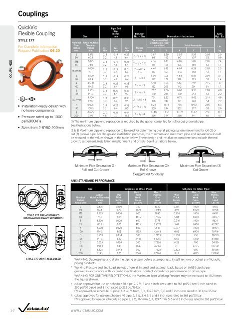
COUPLINGSCouplingsQuickVicFlexible CouplingSTYLE 177For Complete InformationRequest Publication 06.20• Installation-ready design withno loose components• Pressure rated up to 1000psi/6900kPa• Sizes from 2-8"/50-200mmNominalSizeInchesmmSizeActual OutsideDiameterInchesmm(1)MinPipe EndSep.Inchesmm(2)Max(3)MaxBolt/NutNo. – SizeInchesmmPre-assembled(Installation-readycondition)Dimensions – Inches/mmJoint AssembledX Y X Y ZAprx.Wgt. Ea.2 2.375 0.13 0.19 0.253.87 5.59 3.56 5.39 2.05 2.02 – 3⁄8 x 2 ½50 60.3 3.2 4.8 6.4 98 142 90 1.37 52 0.92½ 2.875 0.13 0.19 0.254.36 6.13 4.05 5.89 2.05 2.42 – 3⁄8 x 2 ½65 73.0 3.2 4.8 6.4 111 156 103 150 52 1.13.000 0.13 0.19 0.25 2 – M10 x 4.40 6.13 4.09 6.28 2.02 2.576.1mm76.1 3.2 4.8 6.4 2 ½ 112 160 104 160 51 1.13 3.500 0.13 0.19 0.255.00 7.05 4.68 6.81 2.04 3.12 – ½ x 380 88.9 3.2 4.8 6.4 127 179 119 173 52 1.44 4.500 0.13 0.25 0.385.98 8.24 5.61 7.92 2.15 3.72 – ½ x 3100 114.3 3.2 6.4 9.5 152 209 142 201 54 1.75 5.563 0.13 0.25 0.387.07 9.66 6.68 9.55 2.09 4.82 – ½ x 3125 141.3 3.3 6.4 9.7 180 245 170 243 53 2.25.500 0.13 0.25 0.387.01 9.52 6.71 9.42 2.14 4.9139.7mm2 – M12 x 3139.7 3.2 6.4 9.5 178 242 171 240 54 2.26 6.625 0.13 0.25 0.388.23 11.18 7.95 10.92 2.09 6.32 – 5⁄8 x 3 ¼150 168.3 3.2 6.4 9.5 209 284 202 277 53 2.98 8.625 0.19 0.31 0.4410.48 13.56 10.09 13.42 2.56 10.52 – 5⁄8 x 4200 219.1 4.8 7.9 11.2 266 344 256 341 65 4.7(1) The minimum pipe end separation as required by the gasket center leg for roll or cut grooved pipe.See illustrations below.(2 & 3) Maximum pipe end separation to be used for determining overall piping system movement for roll (2) orcut (3) groove pipe. For design and installation purposes, the minimum and maximum pipe end separations shouldbe reduced to the values shown in the table below. These design and installation considerations include thermalgrowth, settlement, installation misalignment and offsets. See illustrations below.Lbs.kgMinimum Pipe Separation (1)Roll and Cut GrooveANSI STANDARD PERFORMACEMaximum Pipe Separation (2)Roll GrooveExaggerated for clarityMaximum Pipe Separation (3)Cut GrooveSTYLE 177 PRE-ASSEMBLED(INSTALLATION-READY CONDITION)STYLE 177 JOINT ASSEMBLEDNominalInchesActual mmSize Schedule 10 (Steel Pipe) Schedule 40 (Steel Pipe)Max. *ŧ Max. *Max. *§ActualWallJointPermis.WallJointOutside Diameter Thick.Work.EndThick.Work.InchesInchesPress.LoadInchesPress.mmmmpsi/kPa Lbs./Nmmpsi/kPaMax. *Permis.EndLoadLbs./N2 2.375 0.109 750 3322 0.154 1000 443050 60.3 2.77 5170 14780 3.91 6900 197062½ 2.875 0.120 600 3895 0.230 1000 649260 73.0 3.05 4135 17326 5.84 6900 288773 3.500 0.120 600 5773 0.216 1000 962175 88.9 3.05 4135 25678 5.49 6900 427974 4.500 0.120 600 9543 0.237 1000 15904100 114.3 3.05 4135 42448 6.02 6900 707465 5.563 0.134 500 12153 0.258 750 18229125 141.3 3.40 3445 54059 6.55 5170 810886 6.625 0.134 500 17236 0.28 700 24130150 168.3 3.40 3445 76669 7.11 4825 1073368 8.625 0.148 300 17528 0.322 600 35056200 219.1 3.76 2065 77968 8.18 4135 155936WARNING: Depressurize and drain the piping system before attempting to install, remove or adjust any <strong>Victaulic</strong>piping products.* Working Pressure and End Load are total, from all internal and external loads, based on (ANSI) steel pipe,grooved in accordance with <strong>Victaulic</strong> specifications. Contact <strong>Victaulic</strong> for performance on other pipe.WARNING: FOR ONE TIME FIELD TEST ONLY, the Maximum Joint Working Pressure may be increased to 11/2 timesthe figures shown.ŧ cULus approved for use on schedule 10 pipe: 2, 2 ½, 3 and 4 inch sizes rated to 363 psi/25 bar; 5 inch rated to290 psi/20 bar; 6 and 8 inch rated to 232 psi/16 bar.FM approved on schedule 10 pipe: 2, 2 ½, 76.1mm, 3, 4, 139.7 mm, 5, 6 and 8 inch sizes rated to 363 psi/25 bar.§ cULus approved for use on schedule 40 pipe: 2, 2 ½, 3, 4, 5, 6 and 8 inch sizes rated to 363 psi/25 bar.FM approved for use on schedule 40 pipe: 2, 2 ½, 76.1mm, 3, 4, 139.7 mm, 5, 6 and 8 inch sizes rated to 363 psi/25 bar.1-7WWW.VICTAULIC.COM