Datatrac 400 Operations Manual - Aeroflex
Datatrac 400 Operations Manual - Aeroflex
Datatrac 400 Operations Manual - Aeroflex
- No tags were found...

Create successful ePaper yourself
Turn your PDF publications into a flip-book with our unique Google optimized e-Paper software.
OPERATION MANUALDATATRAC <strong>400</strong>ARINC 429 DATABUS ANALYZERMANUAL NUMBER: 06-1403-01 (Hard Copy)E6-1403-01 (CD-ROM)REVISION: 0DATE: 09/26/2006WARNING: INFORMATION SUBJECT TO EXPORT CONTROL LAWSThis manual may contain information subject to the International Traffic in Arms Regulation (ITAR) or the ExportAdministration Regulation (EAR) which may not be exported, released, or disclosed to foreign nationals inside oroutside of the United States without first obtaining an export license. A violation of the ITAR or EAR may besubject to a penalty of imprisonment and/or fines under 22 U.S.C.2778 of the Arms Export Control Act or section2410 of the Export Administration Act. Include this notice with any reproduced portion of this document.This document is proprietary to <strong>Aeroflex</strong>, and is not to be reproduced or otherwisedisseminated without the written consent of <strong>Aeroflex</strong>.<strong>400</strong> New Century Parkway – New Century, Kansas – 66031Telephone: (800) 237-2831 / (913) 764-2452 Fax: (913) 782-5104www.aeroflex.com
Safety and Regulatory InformationReview this product and related documentation to familiarize yourself withsafety markings and instructions before you operate this equipment.WARNINGThe WARNING notice denotes a hazard. It calls attention to a procedure,practice, or the like, that, if not correctly performed or adhered to, could result inpersonal injury. Do not proceed beyond a WARNING notice until the indicatedconditions are fully understood and met.CAUTIONThe CAUTION notice denotes a hazard. It calls attention to an operatingprocedure, practice, or the like, which, if not correctly performed or adhered to,could result in damage to the product or loss of important data. Do not proceedbeyond a CAUTION notice until the indicated conditions are fully understood andmet.Caution (refer to accompanying documents). Attention – refer to the manual.This symbol indicates that information about usage of a feature is contained inthe manual.IMPORTANT!WARNINGThe mains (ac) fuse holder and the dc fuse holder are located on the Rear Panel.An accessory kit of fuses and fuse carriers (caps) is provided, see item ACC4.For international requirements for JPN 01-1403-00 and 01-1403-02 units thefollowing fuses must be used: Install an IEC style, 5 mm X 20 mm, 1.6 A, 250 V,Type F fuse (ACC4F3) into the ac fuse holder, A12XF2 (fuse A12F2), with theproper fuse carrier (ACC4MP2). Also install an IEC style, 5 mm X 20 mm, 1.6 A,250 V, Type F fuse (ACC4F3) into the dc fuse holder, A12XF1 (fuse A12F1), withthe proper fuse carrier (ACC4MP2).For the USA: Install a ¼ X 1 ¼ inch, 1.5 A, 250 V, slow-blow fuse (ACC4F2) intothe ac fuse holder, A12XF2 (fuse A12F2), with the proper fuse carrier(ACC4MP1). Also install a ¼ X 1 ¼ inch, 1.5 A, 250 V, fast-blow fuse (ACC4F1)into the dc fuse holder, A12XF1 (fuse A12F1), with the proper fuse carrier(ACC4MP1).For all other markets check with the proper authorities for which of these kinds offuses to use.
Caution, hot surface. Danger – high temperature surface.Caution (refer to accompanying documents). Attention – refer to the manual.This symbol indicates that information about usage of a feature is contained inthe manual.In-position of a bistable push control. This symbol indicates the in (on)position of a bistable push control.Out-position of a bi stable push control. This symbol indicates the out (off)position of a bi stable push control.CE Mark. of the European Community.Fuse Symbol. To indicate a fuse.WarningsWARNINGWARNINGWARNINGDo not use the equipment in a manner not specified in this manual!Equipment should only be serviced by authorized personnel.To avoid fire hazard, use only a fuse identical in type, voltage rating, and currentrating as specified in this manual.Do Not Operate in Explosive AtmospheresTo avoid explosion, do not operate the equipment in an atmosphere of explosivegas.Do Not Attempt to Operate if Protection may be Impaired.If the equipment appears damaged or operates abnormally, protection may beimpaired. Do not attempt to operate it. When in doubt, have the equipmentserviced.WARNINGKeep the equipment dry to avoid electrical shock to personnel or damage to theequipment. To prevent damage, never apply solvents to the equipment housing.For cleaning, wipe the equipment with a cloth that is lightly dampened with water,mild detergent, or alcohol. Do not use aromatic hydrocarbons, chlorinatedsolvents, or methanol-based fluids.
Ventilation RequirementsFor proper ventilation do not block openings in bottom cover or back panel.WARNINGWARNINGWARNINGWARNINGThis is a Safety Class 1 Product (provided with a protective earthing groundincorporated in the power cord). The mains plug shall only be inserted in asocket-outlet provided with a protective earth contact. Any interruption of theprotective conductor inside or outside of the product is likely to make the productdangerous. Intentional interruption is prohibited.Equipment has recharging circuit for a rechargeable battery. Use only a sealedlead-acid battery as specified by JcAIR Test Systems.Equipment contains a sealed lead-acid rechargeable battery not replaceable byan operator. Replace only with a sealed lead-acid battery as specified by JcAIRTest Systems. Observe polarity of battery when reconnecting.Equipment is not intended for wet locations. Miscellaneous liquids on or in theequipment could cause hazardous conditions.Safety Maintenance.The operator should check the detachable power supply cord condition. Theequipment should not be operated if the appliance inlet is cracked or broken.Any obvious damage to the case (from a drop or fall) should be checked byservice personnel for loose or damaged parts inside. See individual parts lists forapproved replacement parts.WARNINGWARNINGWARNINGCAUTIONWARNINGThe ON/OFF switch (A12S1) only controls dc voltage to the switch mode powersupply (A2) that sources the operating circuitry. The battery (A13A2BT1) isalways charging when there is mains power or dc power applied.To effect primary (mains) disconnect unplug the detachable power supply cordat the appliance coupler or the mains plug.Connect unit to only one external source at a time, either mains power supply ordc power supply.Connection to the dc power supply input dual banana jack (A12J10) shall bewith a dual plug so that both conductors can be disconnected at the same time.If this equipment is used in a manner not specified by the manufacturer, theprotection provided by the equipment may be impaired.
ELECTROSTATIC DISCHARGE GENERAL WARNINGS FOR ALL EQUIPMENTCAUTION:THIS EQUIPMENT MAY CONTAIN ELECTROSTATIC DISCHARGE (ESD) SENSITIVECOMPONENTS. TO PREVENT ESD SENSITIVE EQUIPMENT FROM POSSIBLEDAMAGE, OBSERVE THE FOLLOWING PRECAUTIONS WHEN HANDLING ANY ESDSENSITIVE COMPONENTS, OR UNITS CONTAINING ESD SENSITIVECOMPONENTS:a. Maintenance or service personnel must be grounded though a conductive wrist strap, or a similargrounding device, using a 1 MΩ series resistor for equipment protection against static discharge,and personal protection against electrical shock.b. All tools must be grounded (including soldering tools) that may come into contact with theequipment. Hand contact will provide sufficient grounding for tools that are not otherwisegrounded, provided the operator is grounded through an acceptable grounding device such as awrist strap.c. Maintenance or service of the unit must be done at a grounded, ESD workstation.d. Before maintenance or service of the equipment, disconnect all power sources, signal sources,and loads connected to the unit.e. If maintenance or service must be performed with power applied, take precautions againstaccidental disconnection of equipment components. Specifically, do not remove integratedcircuits or printed circuit boards from equipment while the equipment has power applied.f. All ESD sensitive components are shipped in protective tubes or electrically conductive foam.The components should be stored using the original container/package when not being used ortested. If the original storage material is not available, use similar or equivalent protectivestorage material.g. When ESD sensitive components are removed from a unit, the components must be placed on aconductive surface, or in an electrically conductive container.h. When in storage or not being repaired, all printed circuits boards must be kept in electricallyconductive bags, or other electrically conductive containers.i. Do not unnecessarily pick up, hold, or directly carry ESD sensitive devices.Failure to comply with these precautions may cause permanent damage to ESD sensitive devices. Thisdamage can cause devices to fail immediately, or at a later time without apparent cause.05-0035-00 Rev 03
<strong>Aeroflex</strong> Maintenance <strong>Manual</strong>REVISION HISTORY BY DRAWING NUMBERMANUAL: DATATRAC <strong>400</strong> ARINC 429 Databus Analyzer OperationREVISION: 0 – September 26, 2006REV.REV.DRAWING NO. LEVEL DRAWING NO. LEVELSection I 00Section II 00Section III 00Section IV 00Section V 00Section VI 00Section VII 00Section VIII 00Appendix A 00Appendix B 00Appendix C 00Appendix D 00Appendix E 00Appendix F 00DRAWING REVISION HISTORY – DATATRAC <strong>400</strong> – SEPTEMBER 26, 2006 – PAGE 1 OF 1
<strong>Aeroflex</strong> Operation <strong>Manual</strong>SECTION IV4. Transmit Mode .............................................................................4-14.1 Primary Transmit Setup Screen ...................................................4-14.1.1 Transmitter Channel Selection .....................................................4-24.1.2 Transmitter Channel On/Off .........................................................4-24.1.3 Transmitter Bus Speed Selection.................................................4-34.1.4 Transmitter Mode Selection .........................................................4-34.1.5 Equipment ID Codes ....................................................................4-44.2 Transmitter Default Setup Options ...............................................4-44.2.1 Transmitter Data Format ..............................................................4-54.2.2 Transmit Display On/Off...............................................................4-54.2.3 Transmit Display Lines Selection .................................................4-74.2.4 Transmit Word Bit Gap Selection .................................................4-74.3 Static Transmit Data Keyboard Entry And Display .......................4-74.3.1 Real Time Data Display Screen ...................................................4-84.3.2 Alternate Transmit Edit Screen ....................................................4-104.3.3 Transmit Data Editing...................................................................4-114.3.4 Sample Transmit Data Screens ...................................................4-134.3.5 Burst Mode Transmission.............................................................4-154.3.6 Framing Label Transmissions ......................................................4-154.4 Dynamic Data Transmission ........................................................4-204.4.1 Label And Control Information Setup ...........................................4-204.4.2 Waveform Definitions ...................................................................4-214.4.3 Transmit Data Display..................................................................4-214.5 Prestored Transmit Tables...........................................................4-22SECTION V5.0 Record Mode................................................................................5-15.1 Primary Record Setup Screen......................................................5-15.1.1 Function Setup .............................................................................5-15.1.2 Channel Selection ........................................................................5-25.1.3 Record Interval.............................................................................5-25.1.4 Bus Speed....................................................................................5-25.1.5 Equipment ID Codes ....................................................................5-25.1.6 Label-SDI .....................................................................................5-25.2 Active Recording Screen..............................................................5-25.3 Record Capacity...........................................................................5-35.4 Recorded Data Protection............................................................5-35.5 Recorded Data Review ................................................................5-35.5.1 Numerical Data Review................................................................5-35.5.2 Graphic Display of Recorded Data...............................................5-55.5.2.1 Graphics Screen Setup ................................................................5-55.5.2.2 Time Scale ...................................................................................5-65.5.2.3 Vertical Scale ...............................................................................5-65.5.2.4 Utility Functions............................................................................5-6DATATRAC <strong>400</strong> – REV 0 - PAGE - ii
<strong>Aeroflex</strong> Operation <strong>Manual</strong>SECTION V (Con’t)5.5.3 DAC Download of Recorded Data................................................5-75.5.4 RS-232C Download of Recorded Data.........................................5-8SECTION VI6. Breakpoint Mode ..........................................................................6-16.1 Breakpoint Setup..........................................................................6-16.1.1 Function Setup .............................................................................6-16.1.2 Break Sequence...........................................................................6-26.1.3 Break History................................................................................6-26.1.4 Relative Time ...............................................................................6-36.1.5 Selected History Labels................................................................6-36.1.6 Event Count .................................................................................6-46.1.7 Label/Data Setup .........................................................................6-46.2 Breakpoint Review .......................................................................6-46.3 RS-232 Download of Break History Data .....................................6-76.4 Break History Transmit Function ..................................................6-8SECTION VII7.0 Bite Mode.....................................................................................7-17.1 Bite Setup Menus.........................................................................7-17.2 CFDS Operation...........................................................................7-37.2.1 CFDS Normal Mode.....................................................................7-37.2.2 CDFS Menu Mode .......................................................................7-57.3 CMC Bite Operation .....................................................................7-77.3.1 Ground Test .................................................................................7-97.3.2 Shop Fault Menus ........................................................................7-107.4 737-Bite Mode..............................................................................7-107.5 Bite Screen Recording And Review .............................................7-137.6 RS232 Download of Saved Screens ............................................7-14SECTION VIII8.0 BILLS OF MATERIALS, ASSEMBLY DRAWINGS, AND SCHEMATICSAppendix A...................................................................................................A-1Appendix B...................................................................................................B-1Appendix C...................................................................................................C-1Appendix D...................................................................................................D-1Appendix E...................................................................................................E-1Appendix F ...................................................................................................F-1DATATRAC <strong>400</strong> – REV 0 - PAGE - iii
1.0 INTRODUCTION TO THE DATATRAC <strong>400</strong><strong>Aeroflex</strong> Operation <strong>Manual</strong>SECTION IThis manual is furnished to customers of <strong>Aeroflex</strong> to provide detailed instructions for the operation ofthe DATATRAC <strong>400</strong> ARINC 429 bus analyzer. It contains all necessary illustrations and informationto allow the unit to be properly interfaced with appropriate electronic equipment. The generalcapabilities of the DATATRAC <strong>400</strong> are discussed in the paragraphs below.1.1 SUMMARY OF FEATURESDATATRAC <strong>400</strong> is a four receiver channel and four transmit channel ARINC 429 bus analyzer(Channels 3 & 4 are optional for both receive and transmit functions).The primary modes are Receive, Transmit, Record, Break, and BITE. Also available is an optionalWilliamsburg Protocol Analyzer mode. This option is addressed in a separate user manual.The Receive mode allows data to be read from all installed channels at either low (12.5 kHz) or high(100 kHz) speed. All labels on the bus will be received. The data may be viewed in nine differentformats: hex, binary, engineering (standard and user defined). ASCII. And graphic time plots. Datacan be downloaded via an RS-232C port and a D/A converter port.The Transmit mode allows up to 128 labels per channel to be transmitted at either low or high speed.Other modes supported are dynamic data, prestored tables, burst, and retransmission of recordeddata.The Record mode allows up to 16 labels to be recorded at a selected sample interval between 1 msto 10 s. Up to 120 kbytes of memory are available for storage.The Break mode permits intermittent conditions to be trapped and history data to be collected inmemory. Multi-level break conditions can be defined for trapping data.The BITE mode, supports systems on 737-300/<strong>400</strong>/500, 747-<strong>400</strong>, MD-11, and A320-330/340 aircraft.Up to 240 BITE screens can be saved for later viewing or downloading. ARINC 604 normal andinteractive modes are supported.Product specification is in Appendix B.A database corresponding to ARINC 429-16 is prestored in the DATATRAC <strong>400</strong> EPROM memory.This defines range, scaling, units, etc. to be used in displaying data for various modes. Also includedin the database are special Boeing labels used by equipment in Boeing aircraft. A complete list ofdefinitions for these labels is included in Appendix D.DATATRAC <strong>400</strong> – REV 0 – PAGE 1-1
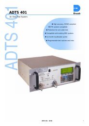
<strong>Aeroflex</strong> Operation <strong>Manual</strong>1.2 REFERENCE DOCUMENTSThe following is a list of references referred to in this manual:1. ARINC 429-16 SPECIFICATION2. SPECIAL BOEING LABEL DEFINITIONS FOR ARINC 4293. DATATRAC <strong>400</strong> WILLIAMSBURG PROTOCOL ANALYZER USER’S MANUAL -VERSION B1.3 PHYSICAL DESCRIPTION1.3.1 GENERALThe DATATRAC <strong>400</strong> is packaged in an aluminum enclosure complete with handle, front panel, rearpanel, and an internal card cage configuration consisting of mother board and plug-in applicationboards. Units may be configured with optional front acrylic cover and rear plastic cover.1.3.2 FRONT PANEL DESCRIPTIONThe front panel configuration shown in Figure 1 contains a LCD, a keyboard area, display contrastcontrol, and the receiver/transmitter connectors.LCDThe liquid crystal display (LCD) provides 16 lines x 40 characters in the character mode. It can alsobe operated in a graphics mode to display time plots of data, with a resolution of 240 dots by 128dots.The contrast control for the display is located to the lower right of the display. This may be adjustedat any time to optimize the viewing of the display.KeyboardThree key areas are located to the right of the display. The first is a vertical column of four functionkeys (RCV, XMT, RCD, and BRK). The next key area consists of a 4 x 4 hexadecimal keypad forgeneral data entry. The third key area consists of the six keys to the far right. Four buttons containup, down, left, and right arrows and are used for various utility functions dependent on mode.Generally, the up/down keys are used to increment vertically through data lists. The left and rightbuttons are used to move the cursor laterally, sequence through setup options, or call help menusappropriate to the existing mode of screen. Located below the arrow keys are the clear (CLR) andenter (ENT) buttons.DATATRAC <strong>400</strong> – REV 0 – PAGE 1-2
<strong>Aeroflex</strong> Operation <strong>Manual</strong>DATATRAC <strong>400</strong> FRONT PANEL OVERVIEWFIGURE 1DATATRAC <strong>400</strong> – REV 0 – PAGE 1-3
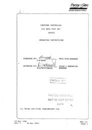
<strong>Aeroflex</strong> Operation <strong>Manual</strong>Databus ConnectorsTwo rows of four BNC connectors provide the databus interfaces for the input receive and outputtransmit channels. The inner conductor on each BNC connector is the A signal (High), of the ARINC429 bus. The outer conductor is the B signal (Low). The channels are labeled appropriately.1.3.3 REAR PANEL DESCRIPTIONThe rear panel shown in Figure 2 contains the ON/OFF switch, power connector for dc power, powerconnector for mains power, the fuse holders, RS-232C connector, the DAC port connectors, and theunit serial number tag.ON/OFF SwitchThe ON/OFF switch applies power to the display and all electronic circuits.Dc Power InputThe red and black banana jacks can be used to apply an input of 28 V dc. The power source shouldbe capable of supplying up to 21 W.Mains Power InputMains power can be applied to the three prong connector. The range of this input is 115 to 230 V ac,50 to <strong>400</strong> Hz, at a maximum of 350 mA.Internal Battery PowerThe unit may also be operated from the internal battery. The battery is a 12 V, 7 Ah sealed lead-acidbattery. A fully charged battery will normally provide up to 6 h of operation. This battery is also usedto retain RAM memory for an indefinite period. RAM memory will be retained even when the batteryhas discharged below the level required to operate the unit. The internal battery can be charged withthe application of either dc or mains power. The charge function employs three levels for rapid andefficient charging. The lower maintenance level may be left on indefinitely.DATATRAC <strong>400</strong> – REV 0 – PAGE 1-4
<strong>Aeroflex</strong> Operation <strong>Manual</strong>DATATRAC <strong>400</strong> REAR PANEL OVERVIEWFIGURE 2DATATRAC <strong>400</strong> – REV 0 – PAGE 1-5
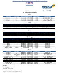
<strong>Aeroflex</strong> Operation <strong>Manual</strong>FusesTwo power input fuses (dc and ac) are located on the rear panel. These fuses should be checkedafter any failure of the unit to power up properly.RS-232 ConnectorAn RS-232 connector is located on the rear panel and can be configured by the operator to outputreceived or recorded data. Appendix A contains detailed information on interfacing this output toother RS-232 devices.DAC ConnectorTwo BNC connectors are located on the rear panel and each provides a DAC (digital to analogconverter) channel that can be configured by the operator to output converted data or a trigger pulse(refer to sections 3-7 for more detail). The inner conductor is the signal side. The outer conductor isconnected to ground. DAC channel 1 is available when Receive Board 1 (RCV channel 1 and 2) ispresent. DAC channel 2 is available when Receive Board 2 (RCV channels 3 and 4) is present.1.3.4 INTERNAL ARCHITECTUREInternally, the unit contains a card cage, and the battery assembly. The card cage arrangementconsists of a front plane and the following plug in cards:- Power supply- CPU/memory- Receiver Ch. 1/2- Transmitter Ch. 1/2- Receiver Ch. 3/4 (optional)- Transmitter Ch. 3/4 (optional)The internal configuration is illustrated in Figure 3.DATATRAC <strong>400</strong> – REV 0 – PAGE 1-6
<strong>Aeroflex</strong> Operation <strong>Manual</strong>DATATRAC <strong>400</strong> INTERNAL CONFIGURATIONFIGURE 3DATATRAC <strong>400</strong> – REV 0 – PAGE 1-7
<strong>Aeroflex</strong> Operation <strong>Manual</strong>2.0 INSTALLATION INFORMATION2.1 UNPACKING AND INSPECTIONSECTION IIThe DATATRAC <strong>400</strong> has been carefully packed to survive all normal shipping and handlingconditions. It is important that the customer immediately inspect the received shipment to ensure thatall items are present and undamaged.Contents:1. DATATRAC <strong>400</strong> unit2. RS Read program for data download to a PC3. Power Cord4. <strong>Manual</strong>WARNINGInspect all items thoroughly for physical damage. If no damage is evident,apply mains or dc power to the unit and change on/off switch to ON. A poweron screen should appear on the display (see section 2.2). If a problem isencountered at this point, contact an <strong>Aeroflex</strong> representative for assistance.DO NOT OPEN THE UNIT AND ATTEMPT REPAIRS AS THIS WILL VOIDTHE WARRANTY.CAUTION2.2 GENERAL POWER ON PROCEDURESThe internal battery should be in a charged state when it is received.However, as a precaution it is recommended that the unit be connected toexternal power overnight before attempting to operate from the internalbattery.External power (dc or mains) can be applied or the unit can be operated on the internal battery. If aunit fails to operate properly on power up, the fuses located on the rear panel should be checked.Upon initial power up of the unit, the various mode setup values will be in indeterminate states. Toreset these values to their defaults, first press the CLR key, then the 0 key. This initialization mayalso be necessary if an erroneous data condition is suspected during real-time operation of the unit,possibly caused by an inadequate battery backup.After turning the on/off switch to the ON position, the following screen will appear on the display (areminder: the contrast control may be adjusted at any time to optimize the viewing of the display).DATATRAC <strong>400</strong> – REV 0 – PAGE 2-1
<strong>Aeroflex</strong> Operation <strong>Manual</strong>** DATATRAC <strong>400</strong> ** S/W Version 025 **Configuration: 2 RCV, 2 XMT ChannelsRCV : Receive DataXMT : Transmit DataRCD : Record DataBRK : Break on Receive DataB : Display BITE DataD : Recall System SetupsSelect function : RCVPress :ENT to continue(Copr. 1991-97 Atlantic Instruments, Inc.)The version number of the current software package contained in the DATATRAC <strong>400</strong> unit is alwaysdisplayed on the first line of the power on menu. This information may be useful when reportingproblems experienced in the field.The configuration of the DATATRAC <strong>400</strong> unit is given on the second line of the menu. The number ofreceived channels and the number of transmit channels contained on the unit and available foroperation are listed.The desired function can be selected from the list of options by pressing one of the four keys, the Bkey (for BITE mode operation), or the D key (for recalling system table) from the hexadecimal keypad.When the desired selection is displayed on the screen, the user “enters” the choice by pressing theENT key. Control will proceed to the appropriate setup screen based on the function selected.DATATRAC <strong>400</strong> – REV 0 – PAGE 2-2
<strong>Aeroflex</strong> Operation <strong>Manual</strong>SECTION III3.0 RECEIVE MODEThe receive mode consists of a primary setup screen, a secondary setup screen (referred to as the"Defaults" screen) and a real-time data display screen. There are also various help screensassociated with each setup parameter. Depending on the system setup, the real-time screen mayalso be shared by one or more transmit channels. Additional setup screens are provided for specialmodes that may be selected.3.1 PRIMARY RECEIVE SETUPAfter a receive mode selection (RCV), the following receive setup screen will appear.Channel: 1* RECEIVER SETUP *On/Off: : OFF Select Lbls: ALLBus Speed: 12.5 Equipment ID: 002> To step through options< To see Help screen for each line^ v To move to next/previous lineD To edit defaultsPress ENT to continue or anyfunction key to change functionsEach setup parameter will initially contain its default value unless changed by a previous setupsession. Before the operator can proceed to the real-time data display screen, a receive channelmust be enabled by setting On/Off to ON. If the user does not wish to change the other defaultsettings, the ENT key may be pressed to continue to the data display (real-time) screen.At any time while in the setup screens, pressing the CLR key will reset all the parameters to theirdefault values. The unit will ask for a confirmation (the C key confirms the action) before continuingwith the reset.Another function of the CLR key is to return to the Main Menu screen. This permits accessing thesystem setup recall function (since there is no dedicated key for this function). After pressing theCLR key, the unit will ask for a confirmation. Pressing F at this point will cancel the initialization andreturn to the Main Menu.DATATRAC <strong>400</strong> – REV 0 – PAGE 3-1
<strong>Aeroflex</strong> Operation <strong>Manual</strong>To change the current settings, the arrow keys should be pressed as instructed on the setup screen.The right arrow sequentially steps through the setup options. The left arrow presents a HELP menuwith information pertinent to the particular parameter selection. The user may return from a helpmenu at any time by pressing ENT.There is an additional list of parameters, accessible in the Receiver Default menu (section 3.2), thatcontrol aspects of the receive function.The following sections describe each parameter listed in the Receiver Setup screen along with thehelp screens associated with each. The help screens are invoked by pressing the HELP key.3.1.1 RECEIVER CHANNEL SELECTIONThis setup line allows the user to select channels 1 or 2 (1-4 if the additional receiver card is installed)for setting up that channel. The channel number may be selected by typing the value directly or byusing the > (right arrow) key to step through the options. Once a channel has been selected, all otherparameter selections will apply only to that channel. This allows each individual channel to beuniquely configured. The help screen for this setup line is shown below (assuming a single receiveboard is installed) :* RECEIVER HELP SCREEN *Receiver Channel Selection:1 - To select channel 12 - To select channel 23 – Not installed4 – Not installedPress ENT to return to setup screen3.1.2 RECEIVER CHANNEL ON/OFFThis setup line is used to enable the currently selected channel for receiving and displaying data.The help screen for this parameter is shown here:* RECEIVER HELP SCREEN *Receiver Channel On/Off Options:ON - To enable the channel forreceiving data.OFF - To disable the channel.Press ENT to return to setup screenDATATRAC <strong>400</strong> – REV 0 – PAGE 3-2
<strong>Aeroflex</strong> Operation <strong>Manual</strong>Turning a channel OFF will not affect the other setup parameters for that channel. However, sincethe channel is disabled, it will not be displayed on the real-time screen. The remaining active channelwindows (receive and transmit, if any) on the real-time screen will be resized to their default values.This will insure that the full screen is always utilized. Consequently, any non-standard displayconfiguration that was defined will need to be redefined if the new real-time screen layout isundesirable.3.1.3 RECEIVER BUS SPEED SELECTIONThis setup line allows the user to select the bus speed for the receiver bus. The proper bus speedmust be selected for the receiver to correctly display data. The help screen for this parameterappears below:* RECEIVER HELP SCREEN *Receiver Bus Speed Selection:12.5 - To select 12.5 KHz low speedbus100 - To select 100 KHz high speedbusPress ENT to return to setup screenThe current bus speed is always displayed on the respective channel header line in the real-timescreen.DATATRAC <strong>400</strong> – REV 0 – PAGE 3-3
<strong>Aeroflex</strong> Operation <strong>Manual</strong>3.1.4 RECEIVE SELECT LABELSThis setup parameter allows the user to control which labels will be displayed on the real time screen.ALL mode causes every label being received on the bus (up to 256 labels x 4 SDI's) to be displayedin numerical order. Common labels with different SDIs are displayed on separate lines. SEL modecauses only the selected labels (up to 16 labels per channel) to be displayed in any desired order.The help screen for this parameter is:* RECEIVER HELP SCREEN *Receive Select Labels Selections:ALL - Display all incoming labelsfor current channel.SEL - Display previously selectedlabels for current channel.EDIT - Setup/edit selected labels.Press ENT to return to setup screenEDIT is selected when the operator needs to access the list of labels being selected either to reviewthem or to make changes to the list. The next section details this operation.3.1.4.1 SELECT LABEL SETUPThe select-labels facility permits the operator to filter out any unnecessary labels that would otherwiseclutter up the real time display screen. It also enables the operator to organize the displaying forsome order other than numeric by label (which is the case in ALL mode). This permits the viewing oftwo related labels next to each other and eliminates the inconvenience of scrolling the display fromone label to the other.DATATRAC <strong>400</strong> – REV 0 – PAGE 3-4
<strong>Aeroflex</strong> Operation <strong>Manual</strong>To utilize this feature, the operator must first define which labels are to be displayed and their order.This is accomplished in the Select Label Setup screen. This screen is accessed by selecting EDIT asthe Select Lbls option and pressing ENT. The following menu then allows the user to enter newlabels or edit previously entered labels. The arrow keys ( ^ , < , > , v) are used to move the cursorposition to the desired label field. The cursor cannot move beyond an undefined label field. The Akey is used to add (insert) at the current cursor position. The E key is used to erase the label at thecurrent cursor position. The CLR key is used to clear all labels for the currently selected channel only(the unit will request a confirmation of this action). Up to 16 label/SDI combinations can be selectedfor each channel.* SELECT LABEL SETUP *Format: Lbl-S (Lbl = Octal, S = 0, 1, 2, 3,or D for don't care)Keys: A = Add label, E = Erase label,CLR = Clear all entriesChannel: 1____ - ___ ____ - ___ ____ - ___ ____ - _______ - ___ ____ - ___ ____ - ___ ____ - _______ - ___ ____ - ___ ____ - ___ ____ - _______ - ___ ____ - ___ ____ - ___ ____ - ___Press ENT to continueWhen EDIT is selected at the Receiver Setup screen, the unit will automatically set the Select Lblsparameter back to SEL after the above screen is exited. The user is not required to return to theReceiver Setup screen to change this parameter from EDIT to SEL.3.1.5 EQUIPMENT ID CODESThe equipment ID code should be entered for the unit to select the proper scaling for each ARINC429 label. The DATATRAC-<strong>400</strong> contains a full implementation of the ARINC 429-16 specification forstand alone words. Some labels may have multiple interpretations when displayed in engineeringunits and the equipment ID determines the correct interpretation. A help menu provides a referencelist of all equipment ID's supported. Equipment ID codes are three-digit hexadecimal values. A newvalue is directly entered using the 0-F keys.DATATRAC <strong>400</strong> – REV 0 – PAGE 3-5
<strong>Aeroflex</strong> Operation <strong>Manual</strong>A portion of the help menu listing of all currently defined equipment ID codes that are supported bythe DATATRAC <strong>400</strong> appears below. The full listing is contained in Appendix D. The user may scrollthrough the list one line at a time using the up and down arrows. The F (forward) and B (back) keysmove the list 10 lines at a time and may be used to scroll more rapidly. It may be more convenient forthe operator to have the list organized alphabetically rather than numerically. This may beaccomplished by pressing A as noted in the help screen header message.* HELP SCREEN * Equipment ID Codes *Press ^,v,B,F to scroll list,A for alphabetic order, 0 for numericPress ENT to return to setup screen001 Flight Control Computer002 Flight Management Computer003 Thrust Control Computer004 Inertial Reference System005 Attitude and Heading Ref System006 Air Data System007 Radio Altimeter008 Airborne Weather Radar009 Airborne DME00A FAC (A310)00B Global Positioning System00D AIDS Data Management Unit010 Airborne ILS Receiver3.1.6 LABEL DATA DEFINITIONSSince the user may not always be familiar with label assignments for parameters he is viewing, a helpmenu gives label data definitions based on equipment ID. This menu is accessed from the Receive,Transmit, Record or break data review screens by pressing the D key. The following example showsthe label definitions for equipment ID 004.Label Definitions * Equipment ID = 004Inertial Reference SystemLbl Parameter Definition010 Present Position-Latitude011 Present Position-Longitude012 Ground Speed013 Track Angle-True014 Magnetic Heading015 Wind Speed016 Wind Direction-True041 Set Latitude042 Set Longitude043 Set Magnetic Heading044 True HeadingPress ^,v.F,B to scroll, ENT to returnDATATRAC <strong>400</strong> – REV 0 – PAGE 3-6
<strong>Aeroflex</strong> Operation <strong>Manual</strong>3.2 DEFAULT RECEIVER SETUP OPTIONSIf the D key is pressed on the primary receiver setup menu, the following menu will appear, allowingthe user to edit additional defaults of the receive mode. (Note: pressing D at the equipment ID fieldwill be interpreted as a data entry.) These receive parameters are listed in a separate screen sincethey typically will be left in their default settings.* RECEIVER SETUP *Channel 1 Default SettingsData Format : ENG Display Lines : 14Interval : INST Bus Monitor : 4Rcv Download : NONE> To step through options< To see HELP screen for each line^ v To move to next/previous linePress ENT to return to main setup menuDATATRAC <strong>400</strong> – REV 0 – PAGE 3-7
<strong>Aeroflex</strong> Operation <strong>Manual</strong>The following sections describe the settings of the various parameters above.3.2.1 RECEIVER DATA FORMAT SELECTIONThis setup line selects the format to be used initially by the receiver real-time display screen. Theformat may also be changed in the display screen by pressing the right arrow (>) key. Two optionsfor this parameter that are not accessible from the real-time screen are EDIT and GRAPH. EDIT isused to create or modify a user-defined data format (see next section). GRAPH enables the real timegraphic time plots of specified labels in lieu of the numerical display. The help screen for thisparameter gives examples of data lines displayed in each format:* RECEIVER HELP SCREEN *Data Display Format Options:ENG - Engineering unitsHEX19L - 19 bit data field-hex-LSB 1stHEX19M - 19 bit data field-hex-MSB 1stHEX32 - 32 bit hexadecimalBIN19L - 19 bit data field-bin-LSB 1stBIN19M - 19 bit data field-bin-MSB 1stBIN32 - 32 bit binaryUSER - Previously defined user formatEDIT - Define/edit user formatGRAPH - Realtime graphic plotPress v for examplesPress ENT to return to setup screen* RECEIVER HELP SCREEN *Examples of Display Format Selectionsgiven the following sample ARINC word:Data: Label 210 Equip. ID = 06Bit 32 24 16 9 8 101010100 11011001 10100010 00010001ENG - Engineering unitsLbl SDI 11 ----- Eng Data --- * SSM Par msec210 10 -1427.19 Kts 10 1 0062Press v for more examplesPress ENT to return to setup screenDATATRAC <strong>400</strong> – REV 0 – PAGE 3-8
<strong>Aeroflex</strong> Operation <strong>Manual</strong>* RECEIVER HELP SCREEN *HEX19L - 19 bit data field - hex - LSB 1stLbl SDI 11-Hex Data-29 SSM Par msec210 10 166CA 10 1 0062HEX19M - 19 bit data field - hex - MSB 1stLbl SDI 29-Hex Data-11 SSM Par msec210 10 A6CD0 10 1 0062HEX32 - 32 bit hexadecimalLbl SDI 32-Hex Data-1 SSM Par msec210 10 54 D9 A2 11 10 1 0062Press v for more examplesPress ENT to return to setup screen* RECEIVER HELP SCREEN *BIN19L - 19 bit data field - bin - LSB 1stLbl SDI 11- -Binary Data - -29 SSM Par msec210 10 0001011001101100101 10 1 0062BIN19M - 19 bit data field - bin - MSB 1stLbl SDI 29- -Binary Data- -11 SSM Par msec210 10 1010011011001101000 10 1 0062BIN32 - 32 bit binaryLbl 32- * --- * --- * Bin * Data --- * --- * --- 1msec210 01010100110110011010001000010001 062Press ENT to return to setup screenThe up and down-arrow keys page through the different help screens above. The USER formatpresents data as ENG unless a different "sub-format" was defined for that label (see next section).The ENG format (and USER format, if so defined) has the capability of displaying discrete bits if thelabel definition in the ARINC 429-16 document specifies it. Note above that the ENG header linecontains an "11" just to the left of the data field. A discrete bit in the data word (bit 11) would bedisplayed in this column as a 0 or 1. Additional discretes -from bit 12 and up are displayed to theright.DATATRAC <strong>400</strong> – REV 0 – PAGE 3-9
<strong>Aeroflex</strong> Operation <strong>Manual</strong>In the BIN32 format, the asterisks (*) on the header line are intended as a reference to a bit's positionin the data word. The asterisks mark the boundaries between nibbles (every four bits), namely, bit 5,9, 13, 17, 21, 25, and 29. Also note that in the BIN32 data display format, the receive interval (msec)displays only three digits instead of four in other formats. The most significant digit is not displayedon the data line due to screen width limitations. If the receive interval is greater than 999 msec, thevalue will be displayed as 999. The operator should switch to another display format to see the fullrate value.3.2.1.1 USER DEFINED DATA FORMAT SETUPThe user-defined format facility gives the operator the ability to bypass the standard ARINC 429 datainterpretation for a particular label and equipment. Up to 16 different format definitions can beentered and stored at a time. When the data display format is set to USER DATA in the header of theactive receive channel window of the real time screen, the incoming labels and selected equipmentIDs for that channel are scanned for any labels that match those stored in the user-defined scalingmemory. If a match is found, the ARINC 429 scaling information is replaced with the user-definedformat.The data types available within a user definition are the two engineering types, BNR and BCD, aswell as the direct data display formats HEX19L, HEX19M, HEX32, BIN19L, BIN19M, and BIN32.When the operator selects EDIT at the Data Format setup line of the Receive Defaults menu, thefollowing screen is presented for defining the data format:* USER DEFINED DATA FORMAT *Format Number: 00Equipment ID: 000Label: - - -Format: HEX19LPress ENT to return to setup screenThe format number is a value between 00 and 15 to be entered by the user. It serves as an index tothe sixteen format definitions.If the equipment ID is left at 000, then all occurrences of the specified label will be processedregardless of the equipment ID selected in the channel's setup screen.DATATRAC <strong>400</strong> – REV 0 – PAGE 3-10
<strong>Aeroflex</strong> Operation <strong>Manual</strong>An octal label must be entered before the cursor can advance to the format line. The > key is used tostep through the format options. If the engineering formats, BNR or BCD, are selected, additionallines are displayed to enable the user to fully specify the bit format of the data word. For a BCD datatype, the format screen appears as follows:* USER DEFINED DATA FORMAT *Format Number: 00Equipment ID: 00Label: 377Format:Max Digit (1, 3, 7, 9): 7Number of Digits (0-6): 5Number of Discretes (0-7): 0Press ENT to return to setup screenBCDRange: 1234560Units: USRThe Max Digit parameter is used to determine how many bits will de dedicated to the most significantdigit (MSD). The MSD always starts with bit 29 and occupies 1, 2,3, or 4 bits for a max digit of 1, 3, 7,and 9, respectively. Thus for a max digit of 7, the MSD will occupy 3 bits, namely bits 27, 28, and 29.This parameter controls the alignment of the other digits in the data word. See the ARINC 429specification for the complete explanation of the BCD and BNR data formats.Beyond the MSD, all remaining digits are packed contiguously with 4 bits per digit. If the number ofdigits is set to less than 6, the remainder of the field is packed with zeros on the right. The position ofthe decimal point is specified by the range parameter. The > key is used at the range line to adjustthe magnitude of the number. The choices for range are the following:1234560123456.12345.61234.56123.45612.34561.23456.123456If the number of digits is less than 6, the undefined digits are set to 0. A 0 in the range indicates adummy place holder and not a decoded digit.DATATRAC <strong>400</strong> – REV 0 – PAGE 3-11
<strong>Aeroflex</strong> Operation <strong>Manual</strong>Discretes can be defined beginning with bit 11 as the first discrete. If, for instance, three discretesare desired, entering a 3 for this parameter would decode bits 11, 12, and 13 and display these asbinary digits. The Units parameter allows the user to specify a three character string to either indicatethe units of the decoded value, or to simply identify the format definition. When the cursor is movedto this line, the DATATRAC <strong>400</strong> will print keystroke instructions for incrementing or decrementingthrough the ASCII table using the F and B keys. The > key is used to step to the next character whenthe current character has been set.The BNR format screen displays a slightly different set of parameters:* USER DEFINED DATA FORMAT *Format Number: 00Equipment ID: 00Label: 377Format:Full Scale Value: 4Number of Bits (6-20): 18Number of Discretes (0-7): 0Press ENT to return to setup screenBNRRange: 1234560Units: USRFull Scale Value specifies the magnitude (+ and -) of the decoded value. The full scale values arediscrete values that are predefined in the DATATRAC. They include all the full scale values currentlylisted in the ARINC 429 specification. The > key is used to step through the options until the desiredfull scale value is displayed. The choices currently defined are (in order they are stored):4 8 32 64 128180 256 512 1024 20484096 8192 16384 32768 131072360 65536 262144 16Beyond the last defined value (16), the unit will display integers followed by a question mark (?), suchas "19?", "20?", and so on up to "31?". These are full scale value storage areas yet to be defined.The operator should avoid selecting one of these as the scaling will be unpredictable.The number of bits specifies the number of significant bits (excluding the sign bit) to utilize in thedecode. The sign bit is always bit 29, and the most significant bit of data is 28. Refer to the ARINCspecification for a complete description.DATATRAC <strong>400</strong> – REV 0 – PAGE 3-12
<strong>Aeroflex</strong> Operation <strong>Manual</strong>Another user-defined format that may be specified is the ASCII format. This format is provided tosupport character-oriented data encoding. There are actually two slightly different schemes incommon use for encoding 7-bit ASCII character data, namely PADDED and UNPADDED, asillustrated below.PADDED ASCII Encoding:3 2 2 2 1 1 12 5 4 3 7 6 5 9 8|P | |P | |P | | ||A | Char 3 |A | Char 2 |A | Char 1 | Label ||R | |D | |D | | |UNPADDED ASCII Encoding:3 3 3 2 2 1 12 1 0 3 2 6 5 9 8|P | | | | | ||A | SSM | Char 3 | Char 2 | Char 1 | Label ||R | | | | | |When the user selects ASCII as the user-format, the screen will appear as follows:* USER DEFINED DATA FORMAT *Format Number: 00Equipment ID: 00Label: 377Format: ASCIICharacter Boundaries: PADDEDPress ENT to return to setup screenDATATRAC <strong>400</strong> – REV 0 – PAGE 3-13
<strong>Aeroflex</strong> Operation <strong>Manual</strong>3.2.1.2 RECEIVE MODE GRAPHICS FORMATInstead of viewing the received data numerically, the operator has the option of displaying incominglabels as graphic time plots. To view graphics data, select GRAPH data format option in the defaultmenu. When the ENT button is pressed twice, the following screen is displayed:TR1CH1_ _ _ _ _ _ _ _ _ _ _ _ _ _ __L001-0x1 _ _ _ _ _ _ _ _ _ _ _ _ _ _ __+00%_ _ _ _ _ _ _ _ _ _ _ _ _ _ __TR2CH0_ _ _ _ _ _ _ _ _ _ _ _ _ _ __Four fields can be edited to achieve the desired graph. These are:CH# - Channel Number. The options are 0, 1, and 2, 3, or 4(assuming 4 receive channels are available). This is thereceive channel that contains the data to be displayedgraphically. A selection of 0 on trace 2 will turn the secondtrace off, enabling the entire screen to be used for trace 1 only(this is the default).L001-0 - Label/SDI. Enter the octal Arinc 429 label and SDI to be displayedgraphically.x1 - Data scaling. The options are 1, 2, 4, 8, 16, 32, 64, and 128.An option of 1 means that the full scale value of the word iscontained within the vertical height of the display, an option of 2means that +/-50% of the full scale word is displayed, and soforth. The > key steps through the options.+00% - Data offset. This is a percentage of full scale that becomes thezero point when the data is graphed. The data offset is appliedbefore the data scaling is applied. Any number from 00% to99% (+/-) may be entered using the 0-9 keys. The > key can beused to step to the next character.DATATRAC <strong>400</strong> – REV 0 – PAGE 3-14
<strong>Aeroflex</strong> Operation <strong>Manual</strong>The horizontal resolution of the graph is 200 dots. Therefore, for a receive interval of 100 ms it willtake 20 s to complete one sweep. When it reaches the end, the display will clear and the plot willresume at the beginning. The relative time from the beginning of the sweep is displayed in secondson the display.The vertical resolution of the graph is 64 dots for dual trace mode and 128 dots for single trace mode.In addition to the keystrokes described above, other keystrokes that are active while in the graphmode are:^,v - Moves the cursor up or down through the setup fields.ENT - Freezes the graphic plot. Toggle to unfreeze. HOLD will bedisplayed in the upper right hand corner of the display. Theelapsed time continues to tick off internally when data is onHOLD.CLR - Data trace clears and starts over.RCV, XMT, RCD, or BRK - Control is passed to the setup screen of the selectedfunction.It is possible to display two separate plots simultaneously by enabling trace 2. The default is trace 2off. This is indicated by the channel number of 0. To enable the trace, move the cursor down to thechannel of trace 2 and select the desired receive channel. The remaining setup lines will appear,prompting the operator to define the plot parameters:TR1CH1L001-0x1_+00%TR2CH0L001-0x1_+00%_ _ _ _ _ _ _ _ _ _ _ _ _ _ __ _ _ _ _ _ _ _ _ _ _ _ _ _ _ _ _ _ __ _ _ _ _ _ _ _ _ _ _ _ _ _ __ _ _ _ _ _ _ _ _ _ _ _ _ _ __ _ _ _ _ _ _ _ _ _ _ _ _ _ _ _ _ _ __ _ _ _ _ _ _ _ _ _ _ _ _ _ _DATATRAC <strong>400</strong> – REV 0 – PAGE 3-15
<strong>Aeroflex</strong> Operation <strong>Manual</strong>When two plots are enabled, the two sweeps will run at the same speed to permit time responsecomparisons. The speed is dictated by the receive time interval of trace 1. The vertical position ofthe trace 2 plot will remain at its last value received.3.2.2 INTERVAL (RECEIVE RATE) FORMAT SELECTIONThe receive rate is the time interval between successive receipts of a particular label for a givenchannel. It is computed in milliseconds and displayed on the real time display line along with thedata. The user may select the format of this receive interval to be the instantaneous, minimum, ormaximum interval. The help menu below is available by pressing < at the setup line.* RECEIVER HELP SCREEN *Receive Interval Format Selections:INST - To display instantaneousinterval in msMIN - To display minimum intervalMAX - To display maximum intervalPress ENT to return to setup screen3.2.3 RECEIVE DATA DOWNLOAD SELECTIONThe user may select one of two modes for downloading received data in real time for furtherevaluation, processing, or archiving. The DAC option allows the user to select a real time conversion(12 bit) of digital data to an analog signal. The RS232 option allows the real time download of data tothe RS-232C port. The help screen for this parameter is:* RECEIVER HELP SCREEN *Receive Data Download Selections:NONE - Data Download is disabled.DAC - Realtime digital to analogconversion of one data word.RS232 - Realtime download of receiveddata on RS-232C port.Press ENT to return to setup screenDATATRAC <strong>400</strong> – REV 0 – PAGE 3-16
<strong>Aeroflex</strong> Operation <strong>Manual</strong>The following sections detail the two download utilities available.3.2.3.1 DIGITAL TO ANALOG CONVERSION SETUPThe DATATRAC <strong>400</strong> is configured with at least one digital-to-analog converter port. A second port isincluded with an optional second receive board. The DAC is a 12-bit converter with a range of +/-10V.The real-time download function of the DAC utilizes the most significant 12 bits of a specifiedlabel/SDI combination. The DAC download function is selected from the Receiver Defaults menu.The following screen for setting up the DAC port will then appear just before control is passed to thereal time data display screen:* DIGITAL TO DC CONVERSION SETUP *DAC Port: 1Channel: 1 Data Offset: +00Label-SDI: 000-0 Scaling: 1> To step through options< To see HELP screen for each line^ v To move to next/previous linePress ENT to continueIt is possible to enter a "don't care" for the SDI (using the D key). The data offset is expressed as apercentage of full scale from 0% to +/-99%. The F key is used to toggle the sign. There are discretesettings for the scaling (data multiplier) of 1 (data left unchanged), 2, 4, 8, 16, 32, 64, and 128. The >key is used to step through these values and select the desired scaling.3.2.3.2 DIGITAL TO RS-232 DATA CONVERSIONReal time download of received data through the RS-232C port is enabled when the operator selectsRS-232 at the Receiver Defaults menu. The download is channel specific, i.e., only the datapertaining to the channel under which the RS-232 was enabled will be downloaded. However, it ispossible to enable the RS-232C port for more than one channel at a time. Each data record (labelreceipt) is transmitted over the RS-232C with the channel number as part of the data, so a hostcomputer receiving the data can distinguish which channel the data line pertains to.DATATRAC <strong>400</strong> – REV 0 – PAGE 3-17
<strong>Aeroflex</strong> Operation <strong>Manual</strong>There are different modes which utilize the RS-232C download, namely, recorded data download andreal time data download described here. In both cases, the bit format of a transmitted byte is thesame. These are:1 start bit8 data bits1 parity bit (odd)0 stop bitsBaud rate = 9600 bpsJust before control passes to the real time data display, the unit will display the following messageprompting the user to verify that the host is ready to receive data:Make sure the RS232 port is connected properly andthat the RS232 receive port is ready to accept data.Press ENT to begin download or any other key toabort the transferThe receiving program on the host should be invoked at this time to insure that no data is lost.Because this is a real-time operation, the DATATRAC <strong>400</strong> is unable to wait for the host. If theDATATRAC <strong>400</strong> detects that the host is not ready, it will simply skip the transmission of the recordpending. To abort the download, any key other than ENT is pressed at the screen above and theDATATRAC <strong>400</strong> will return to the Receiver Setup screen. Note, however, that RS-232 download isstill selected in the default screen. An attempt to proceed to the real-time display will again presentthe above message. To cancel the download, the operator must return to the Receiver Default menuand select a download of "NONE."The unit will only download data while control remains in the real time data display screen. If afunction keystroke causes control to pass to another screen, the RS-232C download will cease untilcontrol passes back to the real time screen via the Receive Setup. That is, only when the operatorpresses ENT from the Receiver Setup screen to proceed to the real time screen will the DATATRAC<strong>400</strong> check to see if the RS-232 download is enabled. If the operator enters the real time screen fromthe Transmit Setup screen, the RS-232 port will stay in a standby mode and not transmit any data.For real time data download, a total of eight bytes are sent over the RS-232 port per label received.The structure of the record as it is transmitted on the RS-232C is defined as follows:DATATRAC <strong>400</strong> – REV 0 – PAGE 3-18
<strong>Aeroflex</strong> Operation <strong>Manual</strong>ByteDescription0 Channel # (1, 2, 3, or 4)1 Label2 Data 1 (bits 9-16)3 Data 2 (bits 17-24)4 Data 3 (bits 25-32)5 Time 06 Time 17 Time 2Label, Data 1, Data 2, and Data 3 are the four bytes of the ARINC word received. The bit order of thelabel byte is already swapped to read directly as the octal ARINC label.Time 0, Time 1, and Time 2 are the BCD encoded values for the relative time the label was received.Time 0 is the least significant byte, Time 2 is the most significant byte. The timer is a countdowntimer such that subsequent label receipts will have a smaller time value. The range is 999,999 ms to000,000 ms, or roughly 17 minutes. Upon reaching a time value of 000000, the timer will wraparound to 999999 and resume counting down. All values are transmitted as binary numbers, not theirASCII representation.When the receiver is operating in the ALL mode, all incoming labels will be downloaded to the RS-232C port. When the receiver is operating in SELECT mode, only the selected labels will bedownloaded.NOTE: Due to the finite baud rate (9600), the user must be careful not to overload the RS-232C port with real-time data at an average rate that exceeds the capacity of the bus. Sincethere are eight bytes per record, it takes the RS-232C port approximately 9 ms per record.Thus for a single label, a transmit interval less than 9 ms would cause an RS-232 overflowresulting in incorrect data being downloaded.3.2.4 RECEIVE DATA DISPLAY LINES SELECTIONThis setup line allows the user to customize the receiver display screen when multiple channels arebeing displayed. The user may select the number of labels (one label per line) to be displayed foreach channel. The size of the display windows on the real time screen are set automatically by theunit each time a receive or transmit channel is enabled (or disabled). The default values are (as afunction of the number of channels enabled):1 channel on - 14 lines per channel2 channels on - 6 lines per channel (or 12 lines total)3 channels on - 3 lines per channel (or 9 lines total)4 channels on - 2 lines per channel (or 8 lines total)DATATRAC <strong>400</strong> – REV 0 – PAGE 3-19
<strong>Aeroflex</strong> Operation <strong>Manual</strong>As an example, the user may choose to display one label for one channel and 11 labels for a secondchannel.It is possible to have more than four channels enabled at one time if an optional second transmit orreceive board is installed. In this case, the receive channels take priority over the transmit channelsfor allocating space in the real-time screen. Any transmit channels that are omitted from the real-timedisplay are handled just as if the DISPLAY parameter for that channel was set to OFF (see TransmitDefaults menu description).Before the Display Lines parameter value for a channel can be increased (assuming multiple channeloperation), space must be freed from another channel. The operator must decrease the DisplayLines value of another enabled channel(s) (receive or transmit) by an equal amount so as to maintainthe maximum total for the number of enabled channels listed above. The help screen for this setupline follows.* RECEIVER HELP SCREEN *Display Line Count Selection:Selects the number of data lines to display for thischannel. This parameter permits the channeldisplay window sizes to be tailored toaccommodate special viewing requirements. Thetotal number of lines cannot exceed 14, 12, 9 or 8for 1, 2, 3, or 4 channels active, respectively.Press ENT to return to setup screen3.2.5 RECEIVE BUS MONITOR SENSITIVITY SELECTIONThe DATATRAC <strong>400</strong> continuously monitors each label that is being displayed for activity. If the unitdetects that a label receipt is overdue, it will flag this inactivity to the operator. An asterisk (*) isdisplayed next to the rate value for that label on the real time screen until the label is detected again.The Bus Monitor setup line allows the user to select the sensitivity of this monitor or to disable themonitor completely. The sensitivity is defined in terms of multiples of the last receive intervalmeasured for a particular label. The options are described in the help screen:DATATRAC <strong>400</strong> – REV 0 – PAGE 3-20
<strong>Aeroflex</strong> Operation <strong>Manual</strong>* RECEIVER HELP SCREEN *Bus Activity Monitor Selection:OFF – Bus Activity Monitor is disabled2, 4, 8, 16, 32, 64 - Specifies the timeperiod, in multiples of most recent receiverate, that the unit waits before flagging alabel as overdue. An * appears next to thelast rate value.Press ENT to return to setup screenThe > key is used to step through the options.3.3 REAL-TIME DATA DISPLAY SCREENThe real-time data display screen is invoked any time the operator presses ENT from the receivesetup or transmit screens and there is at least one channel enabled. If a DAC or RS-232 downloadwas enabled, an intermediate screen will be displayed first before control is passed to this screen.Also, if the user selected EDIT as a Select Lbls parameter value, the Select Label Setup screen willappear first. The real time screen will not be invoked if the user chooses GRAPH as a receive dataformat.The following sections describe the layout of the display screen, the active keys that take advantageof the display features, and other information necessary for proper operation. This sectionconcentrates on the receive function, although the real time display supports transmit channels also.For a description of the transmit data editing features on the real time screen, refer to section 4.3.3.3.1 DATA DISPLAYThe real-time screen consists of channel "windows." There are up to four windows for the enabledreceive and/or transmit channels. If more than four channels have been enabled (with an optionalreceive or transmit board), the receive channels will take priority.The windows consist of a channel header, a format header, and the data area. The following is anexample of the real time screen with one channel active:DATATRAC <strong>400</strong> – REV 0 – PAGE 3-21
<strong>Aeroflex</strong> Operation <strong>Manual</strong>- - - - - - - - - RCV CHANNEL 1 (ALL) - - - - - - - - 12.5Lbl SDI 29 - - Binary Data - - 11 SSM Par ms270 10 1001110101001001001 11 1 0350302 10 1010010010101001001 11 1 0035320 10 1000101010101010000 11 1 0035324 10 0000010001000100100 11 1 0035325 10 0101010101001010010 11 1 0035326 10 0000000000000010000 11 1 0035327 10 0100000100100100100 11 1 0035330 10 0001010001010111100 11 1 0350331 10 1111111111100011010 11 1 0350332 10 1101010100001110000 11 1 0350The channel header line contains channel specific information. The solid box at the left extreme istermed the "active window indicator". When more than one channel is enabled, the active windowindicator indicates which window is being affected by the operator's keystrokes. Note that eventhough a window is not "active", it is still receiving and displaying data in real time. It is only theoperator's keystrokes that are confined to one channel so that other channels are not affected.In this example, the channel's Select Lbls parameter was set to ALL as is indicated on the header.This parameter is displayed to avoid confusion that might arise if the operator has selected SELmode. In SEL mode, the window will only display the selected labels. If the user had inadvertentlyleft SEL mode active, labels might be missing from the list. By referring to the header, the user willknow immediately which mode is active.The bus speed setting (in KHz) is displayed at the right extreme of the header. Upon entering thereal-time screen, the user should check the bus speed on each channel window to verify that they arecorrect.Below is an example of multiple channel operation, in this case with three receive channels enabled(with the optional second receive board installed).DATATRAC <strong>400</strong> – REV 0 – PAGE 3-22
<strong>Aeroflex</strong> Operation <strong>Manual</strong>- - - - - - - - - - - - RCV CHANNEL 1 (ALL) - - - - - - - - - - - 12.5Lbl SDI 29 - - Binary Data - - 11 SSM Par ms270 10 1001110101001001100 11 1 0350302 10 1010010010101001100 11 1 0035320 10 1000101010101010000 11 1 0035- - - - - - - - - - - RCV CHANNEL 2 (SEL) - - - - - - - - - - - - 100Lbl SDI 29 – Hex Data - - 11 SSM Par Tmin. . .no data present . . .HOLD - - - - - - - - RCV CHANNEL 4 (ALL) - - - - - - - - - - - - - - 100Lbl SDI 11 - - Hex Data - - 29 SSM Par Tmax040 01 78889 11 1 *0050041 01 45CBB 11 *0 0050350 01 6ABCD 11 1 ( )In the example above, channel 4 is the active window. Any keystrokes affect only this window. TheHOLD utility is currently active, as indicated in the header. This is described in the next section.Channels 2 and 4 above have in the format header Tmin and Tmax.This appears when the operator selects MIN (in channel 2) and MAX (in channel 4) under Interval inthe Receiver Default menu. In the case of channel 2.,the DATATRAC <strong>400</strong> will latch the minimumreceive interval for each label and display them. In channel 4, the maximum interval is latched anddisplayed. When the instantaneous rate is being displayed, the format header will simply display “ms”(see channel 1).The bus inactivity marker (*) is visible next to the rate of channel 4's label 040. If the bus monitor wasset to 4 for this channel, the asterisk indicates that at least 200 ms have elapsed since the last receiptof label 040-01. See the next section for relevant keystrokes that affect this interval display.If only one data word for a label is received and the unit is unable to compute an interval, an infinity( ) sign is displayed in the rate field (see label 350 in the example).Another feature illustrated in this example is the parity error flag. Label 041 indicates an even parityon the last receipt. This is highlights by the adjacent asterisk. In a typical application, a parity errormight occur once in a stream of data for a particular label. When is does, the unit will display theasterisk for about three seconds, even though the parity returns to “odd”. The “0” alone would flashtoo quickly for the operator to detect that an error has occurred. In this way, the operator can catchparity errors that would otherwise go unnoticed.DATATRAC <strong>400</strong> – REV 0 – PAGE 3-23
<strong>Aeroflex</strong> Operation <strong>Manual</strong>3.3.2 REAL TIME SCREEN KEYSTROKESThe following is a list of all the keystrokes defined for use in the real time display while in a receivechannel window.1, 2, 3, 4 - Change active receive channel. To change the channel affected by keystrokes (shown bythe solid box or "active window indicator"), the operator simply presses the key of the desiredchannel. Of course, the channel must have been enabled in the setup and thus present in the realtime screen. If the channel is not enabled, the keystroke is ignored.^, v - Scroll data up/down. The up/down arrows allow a long list of labels to be scrolled on the activedisplay window. Note: if Tmax or Tmin interval display is active for the window, scrolling will reset thevalues currently displayed.CLR - Clear/reset data. At any time, the CLR key may be used to remove all data from the activedisplay window. The rates are reset (any latched min or max interval is cleared). This might beuseful if spurious transmissions from an external source cluttered the display, and the user wished torefresh the display with current input data.ENT - Freeze (hold) data. When this key is pressed, data in the current active window ceases to beupdated. This state is indicated by the "HOLD" on the channel header (see previous example). Thisutility permits the operator to examine rapidly changing or noisy data. During the hold, the receiverdoes not scan the intervals for minimum or maximum, parity error are ignored, and there is nomonitoring for inactivity. Toggling ENT releases the hold and resumes normal operation.> - Change data format. The data display format for the active channel window can be changed atthe real time screen by pressing the right arrow key. The formats will cycle through the sequence inthe following order: ENG, HEX19L, HEX19M, HEX32, BIN19L, BIN19M, BIN32, & USER. Note thatfor BIN32 format, a limitation on screen width forces the most significant digit (1000 ms) to bedropped. If USER format is selected, the unit will scan the incoming labels on that channel to see ifany match the list of user-defined data format labels defined earlier by the operator. If there is nomatch, the label is displayed in ENG format using standard ARINC 429-16 decode for thatlabel/equipment. See section 3.2.1.1 for a complete explanation of user-defined data types.RCV - Return to the receiver setup screen. This keystroke will exit the real time display and presentthe receive setup screen for the last active receive channel. If an RS-232 download was beingperformed, it will be disabled until control is returned to the real time screen. If the active windowindicator had been in a transmit window, the first push of RCV would move the active windowindicator to a receive window and the second push of RCV would invoke the receive setup screen.DATATRAC <strong>400</strong> – REV 0 – PAGE 3-24
<strong>Aeroflex</strong> Operation <strong>Manual</strong>XMT - Make transmit window the active window. If the transmit channel is enabled and is beingdisplayed on the real time screen, this keystroke will move the active window indicator to the transmitwindow. Any subsequent keystrokes will affect the transmit window. The receive channels willcontinue displaying real time data. Control is passed back to the receive channel window by pressingRCV. If no transmit channel is present in the real time screen, control is passed to the transmit setupscreen and any RS-232C download is terminated.RCD, BRK - Record, Break functions. These keystrokes will cause control to pass out of the real timescreen and to the respective setup screen. Any current RS-232 download is terminated. Theoperator can return to the real time screen by pressing RCV or XMT and then ENT.> - Help menu. The help key calls up the help screen for the real time receive display as shownbelow:* RECEIVER HELP SCREEN *Symbol at header indicatescurrent active channel.* KEY DEFINITIONS *1,2,3,4 Change the active RCV channel.^, v Scrolls data in active channel.> Steps through data formats inactive channel.ENT Holds (freezes) data in activechannel. Toggle to release.CLR Clears receive buffer of activechannel.Press ENT to continueDATATRAC <strong>400</strong> – REV 0 – PAGE 3-25
<strong>Aeroflex</strong> Operation <strong>Manual</strong>4.0 TRANSMIT MODESECTION IVThe transmit mode is invoked by pressing XMT and ENTER from the main power-on menu, or bypressing XMT from any other screen. The transmitter setup features are much like the receiversetup, consisting of a setup screen, various optional menus and help screens, and the real-time datadisplay screen. The transmit setup parameters commonly edited are presented on the primary setupscreen and lesser used function are displayed on the transmit default screen. The default options areaccessed from the primary screen by pressing D for default setups.4.1 PRIMARY TRANSMIT SETUP SCREENThe primary transmit setup screen is shown below:*TRANSMITTER SETUPChannel : 1On/Off : ON Transmit Mode :KEYBus Speed : 12.5 Equipment ID : 002> To step through options< To see help screen for each line^v To move to next/previous lineD To edit defaultsPress ENT to continue or anyfunction key to change functionsEach setup parameter will initially contain its default value unless changed by a previous setupsession. Before the operator can proceed to the real-time display screen (or in special cases thealternate transmit edit Screen), a transmit channel must be enabled by setting On/Off to ON. TheENT key can then be pressed to proceed to the data display and edit screen (either real-time screenof alternate edit screen).At any time while in the setup screens, pressing the CLR key will reset all the parameters to theirdefault values. The unit will ask for a confirmation before continuing with the reset. The user canreturn to the main (power on) menu from the setup screen by pressing CLR then F. This sequencewill not reset the transmit setup.The following sections detail the function of each setup parameter.DATATRAC <strong>400</strong> – REV 0 - PAGE 4-1
<strong>Aeroflex</strong> Operation <strong>Manual</strong>4.1.1 TRANSMITTER CHANNEL SELECTIONThis setup line allows the user to select channels 1 or 2 (1-4 if the additional transmitter card isinstalled) for setting up that channel. The channel number is selected by typing the channel numberdirectly of by using the > key to step through the options. Once a channel has been selected, allsubsequent parameter edits will apply only to that channel. Below is the help menu for thisparameter ( assuming a single transmit board is installed) :*TRANSMITTER HELP SCREENTransmitter Channel Selection :1 - To select channel 12 - To select channel 23 - Not installed4 - Not installedPress ENTER to return to setup screen4.1.2 TRANSMITTER CHANNEL ON/OFFThis setup line is used to enable the currently selected channel for editing and transmitting data. Thehelp screen for this parameter is :*TRANSMITTER HELP SCREENTransmitter Channel On/Off OptionsON - To enable the channel for transmitting data.OFF - To disable the channel.Press ENTER to return to setup screen.DATATRAC <strong>400</strong> – REV 0 - PAGE 4-2
<strong>Aeroflex</strong> Operation <strong>Manual</strong>4.1.3 TRANSMITTER BUS SPEED SELECTIONThe transmitter bus speed setup is explained by the following setup help screen.*TRANSMITTER HELP SCREENTransmitter Bus Speed Selection Options :12.0 - To select 12.0 KHz lowspeed bus.12.5 - To select 12.5 KHz lowspeed bus.14.5 - To select 14.5 KHz lowspeed bus.100 - To select 100KHZ highspeed bus.Press ENTER to return to setup screenThe current bus speed is displayed on the channel headers of the real-time display screen.4.1.4 TRANSMITTER MODE SELECTIONThere are three modes of data transmission available, namely, static data (termed KEY because it isentered on the keyboard in the real-time screen), dynamic data, and data prestored in tables.With static data, the operator enters the four ARINC bytes in any of the available formats. The unitwill then repeatedly transmit (unless burst mode is enabled, see section 4.3.5) that same data patternuntil it is changed, of halted by the operator.Dynamic data mode allows the operator to define a waveform to be transmitted for a specified label.Section 4.4 details this function.Prestored table transmission causes a predefined list of data to be transmitted. This is particularlyuseful when a test application requires several different and extensive transmit setups with long listsof labels. TBL mode permits the user to simply reference a table number in lieu of entering all of thedata associated with a setup. Section 4.5 details this function.DATATRAC <strong>400</strong> – REV 0 - PAGE 4-3
<strong>Aeroflex</strong> Operation <strong>Manual</strong>Below is the help screen for this parameter.*TRANSMITTER HELP SCREENTransmitter Mode Selection :KEY - Keyboard entered data.DYN - Dynamic data.TBL - Prestored transmit tables.Press ENTER to return to setup screen4.1.5 EQUIPMENT ID CODESAs with the receive mode, the equipment ID must be set up to support the engineering format option.See section 3.1.5 for a list of the equipment supported.4.2 TRANSMITTER DEFAULT SETUP OPTIONSThe transmitter default screen is accessed by pressing the D key while in the primary setup screen.This menu allows the user to edit additional transmit setup parameters these transmit parametersare listed in a separate screen since they typically will be left in their default settings.*TRANSMITTER SETUPChannel : 1 Default SettingsData Format : ENG Display Lines : 14Display : ON Bit Gap : 4> To step through options< To see help screen for each line^v To move to next/previous linePress ENT to return to main setup menuDATATRAC <strong>400</strong> – REV 0 - PAGE 4-4
<strong>Aeroflex</strong> Operation <strong>Manual</strong>The following sections describe the functions of the different parameters above.4.2.1 TRANSMITTER DATA FORMATThis parameter determines the format of the data when editing static data. The operator can enterdata in any of the eight formats provided. The same format options used in the receive mode arealso available in the transmit mode, with the exception of the graphic data format. The format canalso be selected at the data editing screen by pressing the > key when the cursor is on the channelheader. An explanation of the different formats is detailed in section 3.2.1. Section 3.2.1.1 describesthe user-defined formatting that also applies to the transmitter. Editing of static data in the differentformats is covered in section 4.3.Note : The user defined format storage area is common between the receiver and thetransmitter. Any formats defined while in the receive setup (of any channel) will apply equallyto all enabled transmit channels. Thus if the operator types a label for editing while the userformatis enabled, and a label/equipment ID match is found with a record in the commonstorage area (even receiver), the format information in the user format record will be usedinstead of the standard ARINC 429 format information.4.2.2 TRANSMIT DISPLAY ON/OFFNormally, when an operator enables a transmit screen, the real-time display screen will contain awindow for that channel to provide a means of editing the data to be transmitted. Unlike receivingdata in real-time, however, it is sometimes not necessary to view transmit data in the real-time screenafter it has been defined. The unit can be directed to transmit data in the background while thedisplay is dedicated to other tasks. This permits the user to free up needed display space on thereal-time screen for displaying receiver data or for providing additional lines to another transmitchannel. The “display” parameter specifies whether of not the particular channel is to appear on thereal-time display screen.If the parameter is set to OFF, the unit will first present the alternate transmit edit screen beforeproceeding on to the real-time screen. The alternate edit screen is very similar to the real-timescreen. However, only the transmit channels that have displayed set to OFF, or transmit channelsthat were omitted from the real-time screen for lack of space, are displayed.Any previously defined data can be reviewed or new data specified on this screen before controlpasses to the real-time screen. Section 4.3.2 discusses the alternate transmit edit screen. Section4.3.3 details the editing of static data, which is the same on this screen as in the real-time screen.When the display parameter is set to ON, space is allocated on the real-time screen for displayingand editing data for the transmit channel selected.DATATRAC <strong>400</strong> – REV 0 - PAGE 4-5
<strong>Aeroflex</strong> Operation <strong>Manual</strong>Note : A limit of four receive and/or transmit channels can be displayed onthe real-time screen at a time. If more than four channels are enabled, theoverflow transmit channels are deferred to the alternate edit screen just as ifthe display was set to OFF (when this occurs, the display lines parameter isset to 0).There are certain limitations in using the alternate edit screen with which the operator must befamiliar :• Since the channels defined in this screen are to be transmitted in the background, there is nomeans of toggling transmit on and off as is possible on the real-time screen. The alternateedit screen windows are always defaulted to ON. Any edits terminated by the ENT keystrokebegin transmitting immediately. They continue transmitting until the channel is turned off atthe setup screen.• The burst mode of transmission is not functional since it requires access to the channelwindow in the real-time screen for sending a burst of data. See section 4.3.5 for thedescription of burst mode.• Since all edits to a channel are performed outside the real-time screen, it is difficult to monitorthe immediate reaction of a receive channel to a transmit edit. If it is necessary to monitorchanges in the received data as a function of changes in the transmitted data, it isrecommended that the display parameter be set to ON so that edits can be performed on thereal-time screen with the received data being displayed.Section 4.3.2 describes the alternate transmit edit screen in more detail. Below is the help screen forthe display parameter :* TRANSMITTER HELP SCREEN *Transmitter Display On/Off Options :ON - This enables the transmit data to beedited or viewed on the display.OFF - This only disables the displaying oftransmit data. It does not affect thestate of the transmitter.Press ENT to return to setup screenDATATRAC <strong>400</strong> – REV 0 - PAGE 4-6
<strong>Aeroflex</strong> Operation <strong>Manual</strong>4.2.3 TRANSMIT DISPLAY LINES SELECTIONThis setup parameter gives the user the capability of customizing the layout of the real-time screenwhen multiple channels are enabled. This is similar to the display lines parameter for the receivesetup. See section 3.2.4 for a complete explanation of this parameter. The help screen is the samefor the receive setup. Setting display lines to 0 is equivalent to setting display to OFF.4.2.4 TRANSMIT WORD BIT GAP SELECTIONThe operator can specify with this parameter the spacing between adjacent transmissions of words.The value is expressed as a multiple of a bit interval or width. The default bit gap is 4 bits, but theoperator can adjust the gap to be any of the integers : 2, 3, 4, 5, 6, 8, or 12. Either direct keypadentry to the > key can be used to select the bit gap. The help screen associated with this parameteris shown below :* TRANSMITTER HELP SCREEN *Transmit Word Bit Gap SelectionSelects the number of bits between words beingtransmitted.Options : 2, 3, 4, 5, 6, 8, 12Make selection by direct keyboard entry or > toscroll through options.Press ENT to return to setup screen4.3 STATIC TRANSMIT DATA KEYBOARD ENTRY AND DISPLAYThis section describes the utilities available for editing and controlling the transmission of data.Transmit data editing (of static, i.e. non-dynamic, Data) can be performed from two logically differentyet very similar screens. These are real-time data display screen and the alternate transmit editscreen. Both screens are described below.DATATRAC <strong>400</strong> – REV 0 - PAGE 4-7
<strong>Aeroflex</strong> Operation <strong>Manual</strong>4.3.1 REAL-TIME DATA DISPLAY SCREENWhen the setup of the transmitter is complete and the operator pressed ENT, control passes to thereal-time data display screen unless one of the following is true :• One of the transmit channels has the “display” default parameter set to OFF,• One of the transmit channels has the display lines parameter set to 0,• More than 4 channels are enabled, causing the real-time screen to omit one or morechannels.If any of the above are true, control passes first to the alternate edit screen to give the operator achance to review and/or edit the channel(s) before proceeding to the real-time screen.Below is an example of the real-time screen with one receive and one transmit channel enabled:----------------------------- RCV CHANNEL 1 (ALL) ------------------12.5Lbl SDI :11-Eng Data-: SSM Par MsNo data present: 0N ----------------------- XMT CHANNEL 1 -------------------------- 12.5Lbl SDI 11 ---- ENG Data-----* SSM Par ms100 00 +123.442 Deg 01 1 0100034 00 0000 100.00 Mhz + 1 0100001 00 +5432.1 NM + 1 0500. . . 00 1 0100DATATRAC <strong>400</strong> – REV 0 - PAGE 4-8
<strong>Aeroflex</strong> Operation <strong>Manual</strong>Section 3.3 describes the general aspects of the real-time screen and will serve as a reference forterms used throughout this section.When the transmit window is made active, a cursor appears at the channel number (in the header).Certain keystrokes only apply when the cursor is at the header. These are :1, 2, 3, 4 – Change active transmit channel. If more than one transmit channel is being displayed onthe real-time screen, the active window indicator (and thus key control) can be moved from onewindow to another by typing the channel number. If the channel selected is not on the real-timescreen, the keystroke is ignored.ENTER - Toggle transmit on/off. This keystroke halts (or resumes) the active channel's transmissionof data. The current status of the channel is displayed on the header (ON in the example above).> - Change data format. The data display format for the active channel’s is changed to the nextformat in the sequence. The formats available are ENG, HEX19L, HEX19M, HEX32, BIN19L,BIN19M, BIN 32, and USER. Note that for BIN32, a limitation on screen width forces the mostsignificant digit of the rate to be dropped.v (down arrow) - Enter data edit field. When this key is pressed, the cursor leaves the header andmoves into the first position of the data area. At this point the unit is ready to accept edit keystrokes.Since the data editing is the same in the real-time and alternate edit screens, it is described in aseparate section (4.3.3).B - Channel burst command. Causes a burst of all burst-mode labels defined to be transmitted. Seesection 4.3.5 for a complete explanation of burst mode.There are other keystrokes (aside from editing keystrokes described in section 4.3.3) that apply whilein the transmit window of the real-time screen whether the cursor is at the header or in the data field :XMT - Return to the transmit setup screen. Any edits that were performed are implemented in thetransmit data fields for the active channel and control passes to the transmit setup screen. If an RS-232C real-time received data download was being performed by a receive channel, it will be disabled.RCV - Make receive window the active window. If a receive window is present on the real-timescreen, key control is passed to it. If more than one receive channel is enabled, control is passed tothe receive channel that was last active. If no receive channel is enabled, control passes to thereceive setup screen. Data transmission continues uninterrupted for all enabled transmitterregardless of whether control is in the real-time screen of not.DATATRAC <strong>400</strong> – REV 0 - PAGE 4-9
<strong>Aeroflex</strong> Operation <strong>Manual</strong>RCD, BRK, - Record, Break, function. Any edits that were performed are implemented in the transmitstream for the active channel and control passes to the corresponding setup screen. If an RS-232Creal-time received data download was being performed by a receive channel, it will be disabled. Datatransmission will continue uninterrupted.Note that the header for each transmit channel display contains an indication of the bus speedpreviously selected for that channel.4.3.2 ALTERNATE TRANSMIT EDIT SCREENThis screen is invoked automatically by the unit when any of the following conditions are true :• One of the transmit channels has the DISPLAY default parameter set to OFF,• One of the transmit channels has the display lines parameter set to 0,• More than 4 channels are enabled, causing the real-time screen to omit one or morechannels.The alternate edit screen uses the same keystrokes for editing (when the cursor is in the data field,not the header) as the real-time screen. These are described in the next section. However, somehearer keystrokes are interpreted differently. Furthermore, only one channel is displayed at a time forreviewing and/or editing. Here is a sample of a alternate edit screen :-ON ----------------------------- XMT CHANNEL 1 ------------------12.5Lbl SDI 11--------ENG Data-------* SSM PAR Rate. . . 00 1 0100It is essentially identical to the real-time screen except for the missing active window indicator (solidblock at the left extreme of the header). The keystrokes that are active when the cursor is at theheader are :1, 2, 3, 4 – Edit new channel. If more than one transmit channel was allocated to the alternate editscreen, typing the channel number causes the corresponding channel to be displayed on thealternate edit screen. The alternate edit screen always uses all 14 display lines for each channel.ENT – Proceed to real-time display screen. This keystroke terminates the alternate edit screen andpasses control to the real-time screen. The transmit data just defined (or reviewed) will continue totransmit in the background.DATATRAC <strong>400</strong> – REV 0 - PAGE 4-10
<strong>Aeroflex</strong> Operation <strong>Manual</strong>4.3.3 TRANSMIT DATA EDITINGEditing transmit data (whether from the real-time screen of the alternate edit screen) commenceswhen the operator presses the down arrow key to move the cursor from the header to the data field.At this point, the octal label can be typed at the first line. When the label is typed, a set of zerodefault values appear for each bit position. The user moves the cursor to desired locations and editsthe contents. Pressing the down arrow increments the cursor to a blank line for a new label. Thecursor can be returned to a previously entered label and the contents edited by using the up andright/left arrows. Transmission being (with the new edited data replacing the existing data) after theENT key is pressed for a given channel.Before a label is entered :------------------------------ XMT CHANNEL 1------------------- 12.5Lbl SDI 11--------Eng Data-------* SSM Par Rate. . . 00 1 0100After a label is entered :--------------------------------- XMT CHANNEL 1------------------------------ 12.5Lbl SDI 11--------Eng Data-------* SSM Par Rate320 00 +000.000 Deg 00 1 0100DATATRAC <strong>400</strong> – REV 0 - PAGE 4-11
<strong>Aeroflex</strong> Operation <strong>Manual</strong>The data field will display dependent on the data format that has been selected for editing. If ENGdata format is selected, the data field will be displayed appropriately for the given label andequipment ID. At this point, the user should use the cursor keys to move to the fields to be edited.Up to 128 labels may be entered on each of the active transmit channels.Key Definitions : - Move cursor left or right to edit data^, v - Move to previous, next label for current channel for editing or adding label.CLR - Clear all data for current channel (must be confirmed with C entry).ENT - Begin transmission of current channel. Cursor will move into header field. At thispoint, 1, 2, 3, or 4 may be entered to move to channel 1, 2, 3, or 4 respectively.When the cursor is in the header field, the v key will move to first line to start dataediting.XMT - Go to transmit setup screen.The following help screen is available when the cursor is at the transmit header line.* KEY DEFINITIONS *For cursor on the channel header line> Step through data formats.ENT Toggle transmit on/off.XMT Return to transmit setup screen.For cursor on a data line - Move cursor left or right to valid edit fields.^ v Move to previous or next label.A Add new label.E Erase current label.CLR Clear channel of all labels.Press ENT to continueDATATRAC <strong>400</strong> – REV 0 - PAGE 4-12
<strong>Aeroflex</strong> Operation <strong>Manual</strong>4.3.4 SAMPLE TRANSMIT DATA SCREENSTransmit channel active : ON --------------------- XMT CHANNEL 1 ---------------------------------- 12.5Lbl SDI 11 ---- Eng Data-----* SSM Par ms210 10 -1427.12 Kts 10 1 0062320 10 +123.456 Deg 10 1 0020324 10 +001.010 Deg 10 1 00202 Transmit Channels active: ON --------------------- XMT CHANNEL 1 -------------------- 12.5Lbl SDI 11 ---- Eng Data-----* SSM Par ms210 10 -1427.12 Kts 10 1 0062320 10 +123.456 Deg 10 1 0020324 10 +001.010 Deg 10 1 0020-ON --------------------- XMT CHANNEL 2 -------------------------100Lbl 32 - * - - - * - - - * Bin * Data - - - * - - - * - - - - - - 1ms322 01010100110110011010001000010001 020323 11000010110010110101110111010011 020324 11111111100001001110101101110010 020325 00001001111110001011101110000000 020DATATRAC <strong>400</strong> – REV 0 - PAGE 4-13
<strong>Aeroflex</strong> Operation <strong>Manual</strong>3 Transmit channels active : ON ---------------------- XMT CHANNEL 1 -------------------- 12.5Lbl SDI 11 ---- Eng Data----- SSM Par ms210 10 -1427.12 Kts 10 1 0062320 10 +123.456 Deg 10 1 0020324 10 +001.010 Deg 10 1 0020- ON ---------------------- XMT CHANNEL 2 --------------------- 100Lbl 32 - * - - - * - - - * Bin * Data - - - * - - - * - - - - - - 1ms322 01010100110110011010001000010001 020323 11000010110010110101110111010011 020324 11111111100001001110101101110010 020325 00001001111110001011101110000000 020- ON ---------------------- XMT CHANNEL 3 --------------------- 100322 01010100110110011010001000010001 020323 11000010110010110101110111010011 020323 11111111100001001110101101110010 0204 Transmit Channels active : ON ---------------------- XMT CHANNEL 1 ----------------------12.5Lbl SDI 11 ---- Eng Data----- SSM Par ms320 10 +123.456 Deg: 10 1 0020324 10 +001.010 Deg 10 1 0020- ON ---------------------- XMT CHANNEL 2 ---------------------- 100Lbl 32 - * - - - * - - - * Bin * Data - - - * - - - * - - - - - - 1ms324 11111111100001001110101101110010 020325 00001001111110001011101110000000 020- ON ---------------------- XMT CHANNEL 3 ------------------------ 100322 01010100110110011010001000010001 020323 11000010110010110101110111010011 020- OFF ---------------------- XMT CHANNEL 4 ----------------------- 12.5Lbl SDI 11 ---- Eng Data----* SSM Par ms210 10 -1427.12 Kts 10 1 0062320 10 -123.456 Deg 10 1 0020DATATRAC <strong>400</strong> – REV 0 - PAGE 4-14
<strong>Aeroflex</strong> Operation <strong>Manual</strong>4.3.5 BURST MODE TRANSMISSIONBurst mode is usually associated with such functions as radio tuning and is a technique involvingtransmitting a label for a limited number of times and at a specified rate before ceasing transmission.The DATATRAC <strong>400</strong> provides the capability of defining a burst mode condition for a label as analternative to the normal transmit rate selection.To set up a burst transmission, enter the label and edit the transmit data field normally. When thecursor is moved to the rate (ms) field, press a B and observe that the B is immediately followed by 16.This is the default number of transmissions of the label that will occur. This number can be edited (avalue between 01 and 99) or the cursor simply moved to the right to edit the transmit rate. Anynumber of burst mode labels may be set up and entered. The burst transmission will occur each timethe user presses B while cursor control is on the transmit window.4.3.6 FRAMING LABEL TRANSMISSIONSThe DATATRAC <strong>400</strong> provides a transmit framing feature that permits the operator to control thetiming of multiple label transmissions. This is useful for simulating LRU's that output several labels atdifferent time intervals.A brief explanation of the DATATRAC's method of framing labels of varying transmit periods is helpfulfor taking full advantage of this powerful feature. Figure 4 illustrates the relation between a frame anda cycle. There are always 60 frames in each cycle. The frame, and thus the frame period is definedby the fastest label on the channel. For example, if label 100 was set up with a 50 ms interval, and allother labels were 200 ms, the frame period for this channel would be 50 ms. If a new label is definedwith an interval of 10 ms, the frame period would change to 10 ms.Given the base (minimum) interval, all other labels' intervals must be one of the following multiples ofthe base: 1, 2, 3, 4, 5, 6, 10, 12, 15, 20, 30, or 60. For example, if the minimum interval is 50 ms,other labels in the channel are permitted to have only the following periods :50, 100, 150, 200, 250,300, 500, 600, 750, 1000, 1500, and 3000 ms. If a label is specified with an interval that does not fallon one of the allowed multiples, its interval will be adjusted to the nearest allowed rate. Note that thedisplay will still indicate the rate entered by the user but will transmit at a different rate. Say, in theabove example, that a label is defined with a rate of 80 ms, since only certain multiples of 50 ms arepermitted, that label will transmit at 100 ms even though the display will still indicate 80 ms.As mentioned before, the minimum interval will define the frame period. At some arbitrary point intime, frame 0 will begin. The transmitter will check all defined labels to see which ones are to betransmitted in this frame. After the minimum interval has elapsed, frame 1 begins, and the transmitteragain scans through the list to transmit the labels of this frame, and so on to frame 59. The cyclerepeats with frame 0 after frame 59.DATATRAC <strong>400</strong> – REV 0 - PAGE 4-15
<strong>Aeroflex</strong> Operation <strong>Manual</strong>Figure 5 gives an example of how to specify which frames will contain which labels. In this example,five labels are defined :Interval StartingLabel (ms) Frame100 0100 01101 0050 00102 0200 02103 0100 00104 0500 12The interval and starting frame number are the two parameters that the operator sets to control thetiming of the label transmissions. The base interval is 50 ms due to label 101. Thus, each frameperiod will be 50 ms, and a complete cycle will take 3 seconds (50 ms X 60 frames) to elapse.The figure shows the order in which each label will be transmitted. Beginning with frame 0, label 101will be transmitted first, then label 103, since the latter's start frame is given to be frame 0. Sincelabel 101 is the minimum interval, it will be transmitted on every frame (this is true regardless of whatits starting frame is). Note, however, in frame 1, that label 100 (with starting frame = 1) is transmittedbefore 101 on the list. When several labels are scheduled to transmit the same frame, the order inwhich they are transmitted is the same as the order in which they are listed on the screen.Frame 2 will contain label 101 first, then 102 with its starting frame = 2, then 103 since its interval of100 ms has elapsed since its last transmission in frame 0. Also, if this was not the first cycle of thetransmit list, label 104 would be transmitted at this point since 500 ms would have elapsed since itslast transmission in frame 52 of the previous cycle.In summary, given each labels transmit interval and starting frame number, a diagram similar to thefigure above can be constructed to illustrate the bus timing. Since all intervals, and these multiples ofthe minimum interval, and these multiples are factors of 20, the timing of every cycle (consisting of 20frames each) is the same.The interval and starting frame number are specified on the label data line of a transmit edit window.The rate is given under the "ms" column. The starting frame number field is off the screen to the rightof the rate value. To access it, the cursor is moved to the right from the last rate digit to skew thedata line and display the frame number (indicated by an "F") this number can be 00 to 19. The figurebelow illustrates a data line (above 101) that is skewed to reveal the starting frame number.Lbl SDI 29- -HEX - -11 SSM Par ms01 00000 00 1 0100 F00101 01 11110 00 1 0100102 01 22222 00 1 0100DATATRAC <strong>400</strong> – REV 0 - PAGE 4-16
<strong>Aeroflex</strong> Operation <strong>Manual</strong>The frame counter in the transmitter that continuously counts from 0 to 59 is reset to 0 to begin a newcycle each time a new minimum interval is specified.Otherwise, adding a new label and/or changing an existing interval of frame number will not affect thesequencing of other labels.For this reason, a delay may be experienced between entering a new data edit and observing thechange at the transmitter output. The delay is due to the transmitter waiting for the transmit count toequal the starting frame number of the new label before transmitting it. In any case, the delay will beno longer than 60 times the minimum interval.DATATRAC <strong>400</strong> – REV 0 - PAGE 4-17
<strong>Aeroflex</strong> Operation <strong>Manual</strong>RELATIONSHIP BETWEEN FRAMES AND CYCLES FIGURE 4DATATRAC <strong>400</strong> – REV 0 - PAGE 4-18
<strong>Aeroflex</strong> Operation <strong>Manual</strong>EXAMPLE OF TRANSMIT FRAMING WITHLABELS OF VARYING RATES AND STARTING FRAMESFIGURE 5DATATRAC <strong>400</strong> – REV 0 - PAGE 4-19
<strong>Aeroflex</strong> Operation <strong>Manual</strong>4.4 DYNAMIC DATA TRANSMISSIONIn addition to static value, the transmit mode allows the user to transmit a programmed dynamicpattern. This form of transmission is selected from the primary transmit setup screen by setting upDYN at the TRANSMIT MODE line and pressing ENT. The following secondary transmit screen thenappears and allows the user to enter up to 10 setups.* DYNAMIC DATA TRANSMIT SETUP *Setup Number : 0 Equipment ID : 002XMT Channel : 1Label : SDI __-_XMT On/Off : OFFXMT Interval : 0100|TR||| / \ A2\ | / | \A1 \ | / | \|| |TF|A1 : -1.000 A2 : +1.000T1 (sec) : 001.000 T2 (sec) : 001.000TR (sec) : 000.000 TF (sec) : 000.0004.4.1 LABEL AND CONTROL INFORMATION SETUPSetup number selection. Each setup (0-9) of a dynamic transmission is given a unique number. Insubsequent editing sessions, entering this number causes all associated selections to be displayedfor either review or editing purposes.Channel selection. The desired transmit channel is entered numerically or by incrementing with theright arrow.XMT ON/OFF Selection. This selection is toggled by using the right arrow. It allows a dynamictransmit setup to remain completely defined and turned on and off as desired.XMT Interval Selection. The transmit interval may be entered numerically or incremented with theright arrow.DATATRAC <strong>400</strong> – REV 0 - PAGE 4-20
<strong>Aeroflex</strong> Operation <strong>Manual</strong>Equipment ID Selection. The equipment ID is entered numerically using the 0-F keys.Label-SDI Selection. The transmit label and SDI are entered numerically.SSM Selection. A decimal number is entered for the SSM if a label corresponding to a BNR wordhas been selected. If a BCD label is selected, this setup line disappears. The SSM may be enterednumerically or by incrementing with the right arrow.4.4.2 WAVEFORM DEFINITIONSThe user moves the cursor through the A1, T1, TR, A2, T2, and TF setup lines using the up anddown arrows. Levels (A1 and A2) are set up as decimal values within the range of +/-1.000. Thevarious time segments may lie between 0.000 and 999.999 seconds. Numeric values are entered inthe usual way.4.4.3 TRANSMIT DATA DISPLAYAfter entering all setup selections, the following display will appear if the display option has been setto ON. ON ----------------- XMT Channel 1 ----------------- 12.5 KHzLbl SDI 11 -------- Eng Data -------* SSM Par ms100 00 +090.000 11 1 0100200 00 DYNAMIC 0100210 00 DYNAMIC 0100220 00 DYNAMIC 0100In this example, a single static label has been set up along with three dynamic labels.Note : When a transmit setup for channels 1 or 2 has already been defined and the user desires tochange the transmit channel number to 3 or 4. The XMT ON/OFF selection field must be toggled Onand OFF to load the setup to the new channel and delete it from the old channel.DATATRAC <strong>400</strong> – REV 0 - PAGE 4-21
<strong>Aeroflex</strong> Operation <strong>Manual</strong>4.5 PRESTORED TRANSMIT TABLESThe DATATRAC <strong>400</strong> has the capability of transmitting data tables that have been programmed intoROM. This feature makes it possible to enter long lists of data in a matter of seconds with a fewkeystrokes instead of manually entering data from the keypad. This is particularly useful in asystematic test environment where the user repeatedly performs a series of tests.Before this feature can be used, the transmit tables must have been programmed into theDATATRAC <strong>400</strong> ROM. <strong>Aeroflex</strong> provides a program called PCTOOLS-<strong>400</strong> that enables the operatorto define their own tables. The output is a binary file that can then be loaded onto a PROM. SeeAppendix C for a description of PCTOOLS-<strong>400</strong>.The table selection screen is shown below. It is accessed from the transmit setup screen byselecting Mode = TBL and pressing ENT.* ROM TRANSMIT TABLES SELECTION *Channel : 1 Table Index: 000IndexDescriptor000 AHRS 001001 AHRS 002002 AHRS 003003 ILS TST1004 ILS TST2005 SATCOM A006 SATCOM B007 MY TBL 0Press ENT to select table orCLR to cancel the table selectionThe mode will remain as TBL until it is changed by the operator. Thus, the table selection screen canalways be accessed quickly by simply pressing XMT then ENT. This is desirable in a testenvironment where the operator needs to call up different tables quickly. Although the channel maybe set to TBL mode, static labels can always be added to the table's data in the transmit edit window.DATATRAC <strong>400</strong> – REV 0 - PAGE 4-22
<strong>Aeroflex</strong> Operation <strong>Manual</strong>The table selection screen provides a directory of all the tables currently defined in ROM. It permitsthe operator to scan the names and indices of the ROM tables. The name, or descriptor, is an 8-character string used to identify a table. The operator can press the up and down cursor keys toscroll the list and change the index of the table to be selected. The index that is displayed at the topof the screen will always correspond to the first directory line displayed. It also indicates which tableis being selected when ENT is pressed. The right cursor key is used to move between the channeland index fields. The channel field allows the operator to select a target transmit channel. At theindex field, the 0-9 keys can be used to enter a table index directly instead of scrolling the list.When ENT is pressed, the selected table begins transmitting and the DATATRAC <strong>400</strong> proceeds tothe real-time data display and edit screen. If the user does not want the selected table to betransmitted, then the CLR key is pressed to exit the selection screen without reading the ROM table.When ENT is pressed to begin the tables transmission, any labels that may have been transmittingpreviously on the target channel will be deleted. On the real-time display screen (or the transmit editscreen if any of the enabled transmit channels has display set to OFF) the selected table's descriptoris displayed at the channel's header. The table's data appears on the screen exactly as if it had beenentered by hand. From this point on, the channel can be edited as before from the keypad.Any changes made to the original table will cause an asterisk (*) to appear to the left of thedescriptor. This serves to flag the user that the table has been corrupted by a manual edit. Theoriginal table can be restored (or a new one activated ) by pressing XMT to return to the transmitsetup, then ENT to pass to the table selection screen. The currently selected table will be displayedon the top line. Pressing ENT again at this point will restore the original table and delete any editsthat were done on the target channel.DATATRAC <strong>400</strong> – REV 0 - PAGE 4-23
<strong>Aeroflex</strong> Operation <strong>Manual</strong>SECTION V5.0 RECORD MODEThe record mode allows data from the various input channels to be saved at a user specified rate andthen played back on the screen or downloaded in various formats. The following sections describethe setup and operation of the record mode.5.1 PRIMARY RECORD SETUP SCREENSelection of record mode causes the display of the following primary setup screen. Up to 16 labelsselected from various channels may be recorded at an interval selected by the user.* RECORDER SETUP *Function : RECORD Channel : 1Rcd Interval : 0050 Bus Speed : 12.5Equipment ID : 002Label-SDI (SDI = 0-3 or D don't care):320-X 324-X 325-X 330-X210-X ___-_ ___-_ ___-____-_ ___-_ ___-_ ___-____-_ ___-_ ___-_ ___-_Press ENT to continue5.1.1 FUNCTION SETUPThree functions are available in addition to the RECORD function shown above. These are describedby this line's help screen presented below.* RECORD HELP SCREEN *RECORD - The memory is cleared and newdata is acquired.REVIEW - Directly displays the datapreviously acquired.DAC - Ports the data in the bufferto the DAC output.RS232 - Ports the data in the bufferto the RS232 port.Press ENT to return to setup screenDATATRAC <strong>400</strong> – REV 0 – PAGE – 5-1
<strong>Aeroflex</strong> Operation <strong>Manual</strong>5.1.2 CHANNEL SELECTIONThe channel setup line provides additional pages in which unique bus speed, label-SDI, andequipment ID entries may be made. The channel value may be entered numerically or incrementedwith the right arrow.5.1.3 RECORD INTERVALThe record interval is specified in milliseconds and can lie with the range of 1 to 9999 milliseconds.This interval will be used for all labels and channels. The interval value may be entered numericallyor incremented with the right arrow.5.1.4 BUS SPEEDThe right arrow should be used to toggle between 12.5 or 100 to set up the bus speed appropriate forthe recorded channel.5.1.5 EQUIPMENT ID CODESThe desired equipment ID is entered numerically using the 0-F hex keys.5.1.6 LABEL-SDIUp to 16 label-SDI's may be selected for recording. These are entered by moving the cursor to anempty position and entering the octal label and decimal value for the SDI. Pressing CLR clears alllabel-SDI setups.5.2 ACTIVE RECORDING SCREENIf the user has set up the RECORD function, pressing the ENT key initiates the recording of data andthe following screen is displayed.* RECORDING *Rcd Interval: 0050Record Count: xxxxCh Lbl SDI 29 - Hex Data - 11 SSM Par1 320 01 04A23 11 11 324 10 0966C 11 11 325 01 22218 11 11 330 01 9DFFF 11 11 210 01 A71D0 11 1Press F to toggle RECORD/STOP statusPress ENT to REVIEW dataDATATRAC <strong>400</strong> – REV 0 – PAGE – 5-2
<strong>Aeroflex</strong> Operation <strong>Manual</strong>Activity of the selected labels may be viewed while they are being recorded and the record countinteger increments up at the selected rate. When the available 32768 bytes of record memory arefilled, data recording and the record count halt. At any time prior to this, the user may elect to press Fto interrupt the recording process or press ENT to review data already recorded. While pressing Fhalts the record process, entering the review mode does not. The RCD key may also be pressed toreturn to the setup screen and restart the process.5.3 RECORD CAPACITYWhen the record mode is activated, data recording will continue until the entire 32768 available bytesof record memory are used. This means that a greater record time is possible when fewer labels areselected and/or a lower record rate is set up. The user may calculate this record capability with theknowledge that for every label receipt four bytes of storage are used. When a single label is recordedat once per second, 8192 seconds or 2.28 hours of record time are available. For four labels at twiceper second, the record time would be reduced by eight and so forth.5.4 RECORDED DATA PROTECTIONAfter data has been recorded, all mode selections which might overwrite the data are inhibited by thefollowing message.WARNING: Continuing with this functionwill overwrite data currently stored inRCD/BRK memory. Press C to continue orany other key to abort . . .This includes reinitiating the record mode or returning to receive mode.5.5 RECORDED DATA REVIEW5.5.1 NUMERICAL DATA REVIEWAt any time during the recording of data, the ENT key may be pressed to move to the data reviewscreen. The following screen allows the user to select channels, labels, initial count, and data formatand then view the appropriate recorded words. The user may move the cursor control (the solidsquare toggled by the ENT key) to either the SELECT (upper half of the screen) or the REVIEW(lower half of the screen).DATATRAC <strong>400</strong> – REV 0 – PAGE – 5-3
<strong>Aeroflex</strong> Operation <strong>Manual</strong>- - - - - - - - - - - RECORD DATA SELECT - - - - - - - - - - -Channel: 1Display: NUMERICLBL-SDI: 210-X Count: 0000- - - - - - - - - - - RECORD DATA REVIEW - - - - - - - - - - -Cnt Lbl SDI 32 - Hex Data - 1 SSM PAR0000 210 10 54 E3 A2 11 11 10001 210 10 54 D9 A2 11 11 10002 210 10 54 B0 A2 11 11 10003 210 10 54 09 A2 11 11 10004 210 10 54 D9 A2 11 11 10005 210 10 54 D0 A2 11 10 10006 210 10 54 D9 A2 11 10 10007 210 10 54 D9 A2 11 10 1Press ENT to toggle SELECT/REVIEWIn the SELECT area of the screen, the indicated selections may be made.Channel - May be selected by entering the channel number directly or using the > keyto scroll through the valid channels.Label-SDI -May be selected using the > key to scroll through the recorded labels for thecurrently selected channel.Display - Option may be selected using the > key to toggle between the options ofNUMERIC and GRAPHIC. NUMERIC is the normal list of data; GRAPHICallows data to be viewed as a time plot.Count - Setup allows the recorded data to be displayed beginning at any recordedcount. This is accomplished by entering a numerical value directly orpressing the > key to scroll the data list.When the cursor control is moved to the REVIEW area of the screen, displayed data may be scrolledby using the F (forward) and B (back) keys to step through eight count blocks of data (one full screen)or the up/down arrows to scroll one count at a time. The data format may be changed similar to thereal time receive data using the > key.In this record data review screen, the recorder may be restarted by pressing CLR and then C (toconfirm). Pressing the RCD key takes control back to the previous RECORDING screen. If datarecording is in process when the user elects to REVIEW data, recording will continue while data isbeing examined. Upon returning to the RECORDING screen, the current count will be displayed.DATATRAC <strong>400</strong> – REV 0 – PAGE – 5-4
<strong>Aeroflex</strong> Operation <strong>Manual</strong>5.5.2 GRAPHIC DISPLAY OF RECORDED DATATo view graphics data, select GRAPH as the data format in the above screen. When the ENT buttonis pressed, the following (example) screen will appear:TR1CH1L210-Xx1+00%C00000.050s_ _ _ _ _ _ _ _ _ _ _ _ _ _ _ _ __ _ _ _ _ _ _ _ _ _ _ _ _ _ _ _ _ _ _ _ __ _ _ _ _ _ _ _ _ _ _ _ _ _ _ _ _TR2 _ _ _ _ _ _ _ _ _ _ _ _ _ _ _ _ _CH1L320-X _ _ _ _ _ _ _ _ _ _ _ _ _ _ _ _ _ _ _ _ _x4+50% _ _ _ _ _ _ _ _ _ _ _ _ _ _ _ _ _C00005.5.2.1 GRAPHICS SCREEN SETUPIn this example the user has edited the set up options for the display of two labels simultaneously.Five fields can be edited to achieve the desired graph. These are:CH # -LXXX-X -x128 -Channel Number. The options are 0, 1, 2, 3, or 4. This is the receivechannel number that contains the data to be displayed graphically. Aselection of 0 turns the trace off (trace 2 only).Label. Toggle through valid record labels using > key.Data scaling. Options of 1, 2, 4, 8, 16, 32, 64 and 128 are available tomagnify the data. Use > key to step through options.+50% - Data offset. A number from 00% to +/-99% may be entered. This is apercentage of full scale that becomes the zero point when the data isgraphed. The data offset is applied before the data scaling is applied.C0001 -Data Counter. The F (forward) and B (back) keys may be used to scrollthrough an entire page at a time or a numerical value may be entered directlyto scroll to a precise point in the record memory. The cursor must be on thisline to scroll data.DATATRAC <strong>400</strong> – REV 0 – PAGE – 5-5
<strong>Aeroflex</strong> Operation <strong>Manual</strong>5.5.2.2 TIME SCALEThe horizontal resolution of the graph is 200 dots. The full scale value in seconds may be computedby simply multiplying 200 by the selected record interval displayed to the left of the plot.5.5.2.3 VERTICAL SCALEThe vertical resolution of the graph is 64 dots for dual trace mode and 128 dots for single trace mode.The data range is the full scale value of the label (defined by the ARINC 429 document) divided bythe scaling integer selected by the user. The value of each dot is then this range, divided by either 64or 128. For example, if the heading label 320 which has a scale factor of +/-180 deg is presented inone half of the display area, a scale factor of 1 would mean that the full +/-180 deg range occupiedhalf of the screen with each dot worth 360/64 = 5.62 deg. Likewise, a scale factor selection of 32would mean the graph range was +/-5.622 deg and the value of each dot, 0.17 deg.5.5.2.4 UTILITY FUNCTIONSThe following utility functions are available:^ , v- Moves up or down through the set up fields.> - Steps through the options for certain set up fields.CLR - Data trace clears and starts at a count of 0000.RCDRCV,XMT,BRK- Exit graphics mode and return to the Record Data Review screen.- Record mode will be turned off and the new mode will be selected.If trace 2 is turned off (by entering a 0 for the channel number), the active trace 1 will use the entiredisplay for graphing data.DATATRAC <strong>400</strong> – REV 0 – PAGE – 5-6
<strong>Aeroflex</strong> Operation <strong>Manual</strong>One trace active:TR1CH1 _ _ _ _ _ _ _ _ _ _ _ _ _ _ _ _ _L210-Xx1_ _ _ _ _ _ _ _ _ _ _ _ _ _ _ _ _+00%C0000 _ _ _ _ _ _ _ _ _ _ _ _ _ _ _ _ _0.050sTR2CH0_ _ _ _ _ _ _ _ _ _ _ _ _ _ _ _ __ _ _ _ _ _ _ _ _ _ _ _ _ _ _ _ __ _ _ _ _ _ _ _ _ _ _ _ _ _ _ _ _5.5.3 DAC DOWNLOAD OF RECORDED DATAIn the initial record mode set up screen, one of the four function options allows the downloading ofrecorded data via the DAC port. Pressing ENT with this function selected results in the DAC screenbelow. When the DAC function is selected, further set up is performed on the following screen:* DIGITAL TO DC CONVERSION SETUP *DAC Port : 1Channel : 1 Data Offset : +00LBL-SDI : 101-X Scaling : 1> To step through options< To see HELP screen for each line^ v To move to next/previous linePress ENT to continueThe set up options control the download of data through the DAC port which begins when theoperator presses ENT.DATATRAC <strong>400</strong> – REV 0 – PAGE – 5-7
<strong>Aeroflex</strong> Operation <strong>Manual</strong>DAC 2 may be selected only if a second receive board is installed. The desired channel and label-SDI selected by using the > key to step through valid selections. The data offset may be 00%through +/-99% and will cause the output electrical null to be positioned within the word's full scalerange as indicated. Scaling options are 1, 2, 4, 8, 16, 32, 64 and 128. These magnify the data withinthe output electrical range. The offset adjustment is applied first and then the scaling adjustment.The DAC performs a 12 bit to +/-10.0 VDC conversion.Pressing ENT after all set up options are selected will begin the download. Data is output at onerecord data point every 100 ms, regardless of the record interval.5.5.4 RS-232C DOWNLOAD OF RECORDED DATAIn the initial record mode set up screen, one of the four function options allow a download of recordeddata via the RS-232C port. Pressing ENT with this function selected causes all recorded memory tobe output immediately. The output format consists of data records each representing a singlelabel/data sample. The output begins with the first data sample for the first record word set up.Subsequent data samples for this label are output and after completing the output for a particularlabel, the next label in the selection sequence is output. The record structure consists of 8 bytesarranged as follows:ByteData1 Status = 0, 12 Channel = 1, 2, 3 or 43 Label4 Data 1 (bits 9-16)5 Data 2 (bits 17-24)6 Data 3 (bits 25-32)7 Sample Count (low byte)8 Sample Count (high byte)Status indicates if the label was actually received during the sample interval. If the label was notreceived, status = 0. This is indicated on the review screen as " . . . " on the data line. If the labelwas received, then status = 1. When status = 0, the data in Data 1-3 of the record is invalid andshould be disregarded.The sample count is a 16-bit unsigned binary word that specifies the record's relative position inmemory. The first sample of a recording session has a count of zero.When the RS-232 selection is entered, a message is displayed to remind the user to make sure theRS-232C port is connected properly, and then after pressing the ENT key the following screen isdisplayed:DATATRAC <strong>400</strong> – REV 0 – PAGE – 5-8
<strong>Aeroflex</strong> Operation <strong>Manual</strong>* RS232 DOWNLOAD *TRANSMITTING . . . Please wait while thedata is being downloaded on the RS232.Records remaining to transmit: 0100Press CLR to abort downloadSee Section 3.2.3.2 for the RS-232 interface format specification.DATATRAC <strong>400</strong> – REV 0 – PAGE – 5-9
<strong>Aeroflex</strong> Operation <strong>Manual</strong>SECTION VI6.0 BREAKPOINT MODEThe Breakpoint mode is a versatile tool for troubleshooting avionics equipment. It involves the use ofbreakpoints, history data, and trigger pulses. The breakpoint may be manually initiated by the user orconsist of a complex programmed condition involving one or more labels, event sequences, and datavalues.6.1 BREAKPOINT SETUPEntering a BRK function selection results in the following screen:* BREAK MODE/TRIGGER PULSE SETUP *Function : BREAK Real Time : OFFBrk Sequence : A History : ALLBrk Position : --*-- Event Cnt : 01*A* Channel: 1 Label: 000 Cond: EQData: XXXX XXXX XXXX XXXX XXXX XXXXBit: 32 25 24 17 16 9*B* Channel: 1 Label: 000 Cond: EQData: XXXX XXXX XXXX XXXX XXXX XXXXBit: 32 25 24 17 16 9Data = 0, 1, or X (D-Don't care)Press ENT to continue6.1.1 FUNCTION SETUPThe various function options are illustrated in the following help menu:* BREAK MODE / TRIGGER HELP SCREEN *Function Selections:BREAK - To setup a break condition andsave history data.REVIEW - To review previously collectedhistory data.TRIGGER - To setup a condition for a triggerpulse output on received data.RS232 - Enable RS-232 history data download.XMT - Permit ARINC 429 transmissionof history data.Press ENT to return to setup screenDATATRAC <strong>400</strong> – REV 0 – PAGE 6-1
<strong>Aeroflex</strong> Operation <strong>Manual</strong>The trigger option is a related function that does not involve an actual break but provides triggerpulses whenever the programmed label/data conditions occur.6.1.2 BREAK SEQUENCETwo labels and corresponding data may be set up and are referred to as the A and B conditions. Thebreak sequence options described in the following help screen are allowed.* BREAK MODE / TRIGGER HELP SCREEN *Break Sequence Selections:A - Break only on condition AB - Break only on condition BA or B - Break on either condition Aor condition BA then B - Break on condition B aftercondition A has occurredA Imm B - Break on condition B occurringimmediately after cond APress ENT to return to setup screenThe break condition known as “A Imm B” is defined as condition B occurring on the very next dataword read after condition A has occurred. No other labels may be read between the A and Bconditions.6.1.3 BREAK HISTORYThe history involves a time window of data including not only the specified labels but all other labelson all channels. This window can be programmed to precede the break, follow the break, or consistof some combination of the two. The options are described in the following help menu.DATATRAC <strong>400</strong> – REV 0 – PAGE 6-2
<strong>Aeroflex</strong> Operation <strong>Manual</strong>* BREAK MODE / TRIGGER HELP SCREEN *Break Position Selections:* - - - - : Beginning of memory- * - - - : First quarter of memory- - * - - : Middle of memory- - - * - : Third quarter of memory- - - - * : End of memoryThis defines the relative locationof the break condition in the historymemory.Press ENT to return to setup screen6.1.4 RELATIVE TIMEThe relative time option allows a "time stamp" to be saved along with each history word. In this waythe time associated with each data receipt may be reviewed along with the data. Two time stampoptions are available: 1 ms or 10 µs. When 1 ms is selected the max range of time is 999.999seconds. When 10 µs is selected the max range of time is 9.99999 seconds. By turning off theoption, more memory is available for data storage. With the time stamp ON, 8 bytes of memory arerequired for each history point; with the time stamp OFF, 5 bytes are required for each point.6.1.5 SELECTED HISTORY LABELSA set up line allows the user to restrict the history retention to selected labels rather than all labels.User options are therefore:ALL - Save all data on all active channels. A channel is turned on or off in theappropriate RCV setup menu.SEL - Save only those labels previously setup.EDIT - Set up the select labels.Entering the EDIT option cause the identical set up menu described for the receive mode to bedisplayed (see section 3.1.4.1). Break mode uses the same select labels list that receive mode uses.DATATRAC <strong>400</strong> – REV 0 – PAGE 6-3
<strong>Aeroflex</strong> Operation <strong>Manual</strong>6.1.6 EVENT COUNTThe event count set up has a default of 01 which means the breakpoint will occur onthe first occurrence of the programmed conditions. Entering an integer up to 99 willrequire the conditions to occur that number of times before the breakpoint will begenerated.6.1.7 LABEL/DATA SETUPIn the "A" and "B" label fields, the user is allowed to select the channel, label, condition, and datapattern (bits 9 through 32). An X in a data bit location means that it will be ignored and only those bitscontaining 0's or 1's will be compared with received words. The breakpoint conditions options are asdescribed in the following help menu:* BREAK MODE / TRIGGER HELP SCREEN *Condition Selections:EQ - All defined bits are equal.NEQ - Any defined bit is not equal.OR - Any defined bit is equal.GT - The received word is greaterthan the defined word.LT - The received word is less thanthe defined word./GT/ - The absolute value of the rcv'dword is > the defined word./LT/ - The absolute value of the rcv'dword is < the defined word.Press ENT to return to setup screen6.2 BREAKPOINT REVIEWAfter specifying all breakpoint setup options, the ENT key is pressed to initiate the breakpoint. Thefollowing message will be displayed at the bottom of the setup screen until the break occurs or untilanother key is entered.** Waiting on Break condition . . . **** Press ENT for manual break **** or CLR to abort acquisition **When the break occurs, the message changes to:** Break detected. Wait for history **** data to fill or press ENT to stop **DATATRAC <strong>400</strong> – REV 0 – PAGE 6-4
<strong>Aeroflex</strong> Operation <strong>Manual</strong>When the break occur, a 5 volt, 0.1 ms trigger pulse is transmitted from the No. 1 D/A port. Afterhistory has filled, the following history display screen appears:- - - - - - - - BREAK HISTORY DATA SELECT - - - - - - - -Channel : ALL Time : ELAPSEDLabel-SDI : XXX-X Count : 00336- - - - - - - - BREAK HISTORY DATA REVIEW - - - - - - - -Cnt C Lbl S 11- - - Eng Data - - - * S P ms336 1 300 3 80 00 03 03 3 1 0423337 1 100 3 +090.000 3 1 0517338 1 200 3 -090.000 3 1 0520339 1 300 3 80 00 03 03 3 1 0523340 1 100 3 +090.000 3 1 0617341 1 200 3 -090.000 3 1 0620342 1 300 3 80 00 03 03 3 1 0623343 1 100 3 +090.000 3 1 0717Press ENT to toggle SELECT/REVIEWVarious utility features are available to review history data. These include:Select Field:Cursor control - The dark square is toggled between the upper SELECT areaand the lower DATA REVIEW area by pressing the ENT key.← - This arrow next to the CNT field indicates data point wherebreak occurred.CLR Key - The CLR key returns control to Break setup menu.Channel:The user may view data from ALL channels or individual channels. The right arrow keyselects the options.DATATRAC <strong>400</strong> – REV 0 – PAGE 6-5
<strong>Aeroflex</strong> Operation <strong>Manual</strong>Label-SDI:The user may view all received labels integrated into a time sequence or view the timesequence of individual selected labels. To view individual labels, the user may type in thelabel-SDI using 0-F keys. "D" may be used for don't care in the SDI field. When D is typedinto the first digit field the label goes to XXX-X, which mean all labels. When the data historywas set to SEL in the setup menu, the > key may be used to scroll through valid labels for theselected channel. When a new label is entered, the display of the label begins at the currentcount. If the message " . . not found . . " is displayed, this means that no occurrences of thislabel were found from the current count to the end of memory. It does not indicate that noneexisted in the entire history buffer. The user should set the count to zero to check if anyoccurrences of the selected label are found anywhere in the history buffer.Time:ELAPSED or DELTA may be selected for reviewing data. When ELAPSED is selected, thetime given for each data point is the total elapsed time from data point zero. When DELTA isselected, the time given is the time from the previous data point on the display. The units ofthe time stamp is dependent on the selection made on the Break setup screen (1 ms or 10µs) and is shown in the review header.Count:The Count selection line allows the user to enter a count value. The displayed data in thelower part of the screen responds to changes to the count value.Review Field Keystrokes:0 - The 0 key always returns the data list to the beginning of thehistory buffer, count zero.1 - The 1 key always returns the data list to the count value at which the breakoccurred. The break point is indicated by the arrow next to the Cnt column.E - The E key always returns the data list to the end of the history buffer.> - The right arrow key steps through the data format options.< - The left arrow key displays the HELP menu for Break Review.DATATRAC <strong>400</strong> – REV 0 – PAGE 6-6
<strong>Aeroflex</strong> Operation <strong>Manual</strong>UP - The up arrow key scrolls back through data history one data point at a time.DOWN -The down arrow key scrolls forward through data history one data point at atime.B - The B key scrolls back through 8 data points at a time.F - The F key scrolls forward through 8 data points at a time.6.3 RS-232 DOWNLOAD OF BREAK HISTORY DATAOne of the options available under function in the break setup screen is RS-232 download of historydata. Pressing ENT with this function selected causes the RS-232 "ready screen" to be displayed,prompting the user to insure that the port is connected and the receiving port is ready to accept data.Upon pressing ENT once more, the data will immediately begin downloading. The output formatconsists of a header record, then data records for each label sample stored.The header record consists of 5 bytes defined as follows:ByteData0 Number of samples (low byte)1 Number of samples (high byte)2 Trigger position (low byte)3 Trigger position (high byte)4 Bytes per sample (5 or 8)All values are passed as binary numbers. The bytes-per-sample parameter is necessary because thesample size varies depending on whether the data was collected with a time stamp or not. The timestamp occupies three bytes.The data records consist of 5 or 8 bytes, as specified by bytes-per-sample above.The record structure is:ByteData0 Sample count (low byte)1 Sample count (high byte)2 Channel number (1-4)3 Label4 Data bits 9-16 (Data1)5 Data bits 17-24 (Data2)6 Data bits 25-32 (Data3)DATATRAC <strong>400</strong> – REV 0 – PAGE 6-7
<strong>Aeroflex</strong> Operation <strong>Manual</strong>If sample size = 8, also:ByteData7 Time in BCD (low byte)8 Time in BCD (middle byte)9 Time in BCD (high byte)All values (except the BCD time) are transmitted as binary values.The sample count is a 16-bit unsigned binary word that specifies the record's relative position inmemory. The first record in memory has a sample count of 0000. The trigger position given in theheader record is the sample count of the label record that caused the break. See section 3.1.2.3.2 forthe RS-232 interface format specification. Also, Appendix A gives information on the cabling and thePC program RSREAD provided for reading the RS-232 download.6.4 BREAK HISTORY TRANSMIT FUNCTIONA useful feature available as part of the Break mode utility on the DATATRAC <strong>400</strong> is theretransmission of previously acquired break history data. With this function, the operator can directthe DATATRAC to output labels found in buffer memory at the same relative timing at which theywere received during a previous acquisition. All of the labels received on a certain receive channelwill be output on the corresponding transmit channel, e.g., data received on RCV1 will be output onXMT1.To utilize this feature, a break history acquisition must be performed first. It is necessary to enablethe time stamp to either 1 ms or 10 µs so that the relative timing can be referenced during latertransmission. When the acquisition is complete, return to the break setup screen by pressing theCLR or BRK key from the data review screen. At the Function field, select "XMT" with the right arrowkey and press ENT. Assuming a proper acquisition with time stamp was performed, the followingmessage screen will appear prior to beginning the transmission:* BREAK HISTORY TRANSMIT *Verify that the necessary transmitchannels are connected to the unit undertest and that the unit is ready toreceive data. Press ENT to begin downloador any other key to abort transfer.Upon verifying that the transmit channels are properly connected to the unit under test, the operatorpresses ENT to begin the buffer retransmission.DATATRAC <strong>400</strong> – REV 0 – PAGE 6-8
<strong>Aeroflex</strong> Operation <strong>Manual</strong>Just prior to beginning the transmission, the DATATRAC will reference the RCV channel bus speedsand set the corresponding XMT channels to these same values. The operator must therefore insurethat the RCV channel bus speeds are not changed after an acquisition is performed. If the RCV busspeed is changed before the break history transmit is initiated, the data will be retransmitted at thenew bus speed specified in the corresponding RCV channel.TIP:It is possible to convert data from a low-speed bus to a high-speed bus or visa-versaby first performing a break acquisition at the source unit's bus speed. Then theDATATRAC's RCV channel bus speed is edited to the new desired value. The breakhistory transmit will then output the previously acquired data at the newly selectedbus speed.When the download begins, the following screen will appear:* BREAK HISTORY TRANSMIT *Records remaining to transmit: 12345Press CLR to terminate transmit,ENT to pause/resume transmitAt any time during the download, the operator can press CLR to abort the transmission and return tothe break setup screen. The transmission can be paused and resumed by toggling the ENT keywithout missing any labels.During the retransmission of history data, the XMT channels affected are temporarily disabled fromnormal operation for the duration of the download. Any table that was transmitting at the time on theaffected channel will stop transmitting. When the download is complete, the XMT channels' originalbus speeds are restored and any table transmission that was interrupted is resumed.DATATRAC <strong>400</strong> – REV 0 – PAGE 6-9
<strong>Aeroflex</strong> Operation <strong>Manual</strong>SECTION VII7.0 BITE MODEThe DATATRAC <strong>400</strong> provides an interactive databus communication function to support the BITEsystems used in the newer air transport aircraft. The DATATRAC <strong>400</strong> supports three versions ofBITE: CFDS, CMC and a 737-300 menu BITE mode. The CFDS and CMC modes are described byARINC 604.CFDS is based on the fault isolation function residing in individual LRU's. ASCII textmessages are transmitted from LRU's on command and provide a series of maintenance descriptionsbased on data stored in the LRU's non-volatile memory.The second BITE mode is CMC. With this system, the packed discrete maintenance information in350 series labels is normally transmitted from LRU's to a central maintenance computer for faultprocessing and isolation. When this system is selected, the DATATRAC <strong>400</strong> unpacks and displaysthe maintenance words along with bit definitions prestored and available for all 700 series avionicsequipments.The third BITE version is the 737-300. Similar to the CFDS BITE with a different handshake protocol,ASCII text messages are transmitted from LRU's non-volatile memory.7.1 BITE SETUP MENUSPressing B from the initial mode selection screen or the receive setup menu causes the BITE MODESETUP screen below to be presented.* BITE MODE SETUP *Function : CFDS-MENU ABD0018LRU : IRS 704 RCV Channel : 1Date : mm-dd-yy RCV Speed : 12.5Time : 00:00.0 XMT Channel : 1Shop/AC ID : 000000000 XMT Speed : 12.0Flt Phase : XMT SDI : 0Flt Number : 00000000Extra Lbls : NOCity Pairs : ABCD-EFGHPress ENT to continue or anyfunction key to change functionsDATATRAC <strong>400</strong> – REV 0 – PAGE 7-1
<strong>Aeroflex</strong> Operation <strong>Manual</strong>The choices available for the Function setup line are:The LRU options are:CFDS-MENU ABD0018 777-OMSCFDS-MENU ABD0048 737-BITECFDS-NORM ABD0018 TDR94_350CFDS-NORM ABD0048 REVIEWABD0048 DISCRETERS232747-CMC704 IRS706 DADC707 RALT708 WXR709 DME710 ILS711 VOR712 ADF716 VHF718 ATC718 ATC/S719 HF723 GPWS724 ACARS727 MLS735 TCAS740 PRNTR741 SATCM000 ALL CALLID xxx, where the equipment ID, xxx, may be typed directly in using the 0-F keys.DATE:TIME:The date may be entered on the third setup line using the 0-9 keys. Data is enteredas mm-dd-yy, where mm is the month (00 . . 12), dd is the day (00 . . 31), and yy isthe year (00 . . 99). This date is then transmitted on label 260 at a frequency onetenthof label 227 (typically 1 s).The time may be entered on the fourth setup line using the 0-9 keys. Data is enteredas hh:mm.m, where hh is the hour (00 . . 23) and mm is the minutes (00.0 . . 59.9).This time is then transmitted on label 125 at a frequency one-tenth of label 227(typically 1 s).DATATRAC <strong>400</strong> – REV 0 – PAGE 7-2
<strong>Aeroflex</strong> Operation <strong>Manual</strong>SHOP CODE:A shop code may be entered as a 7 digit code using keys 0-F. This code isthen transmitted as ASCII data in labels 301, 302, and 303 at a frequency ofone-thirtieth of label 227 (typically 3 s).Label 155 is also transmitted at one-tenth the frequency of label 227, whereis the printer device enable label.FLIGHT PHASE:FLIGHT NUMBER:CITY PAIRS:The flight phase may be selected for transmission on label 126. Flight phaseis valid only for 747/777 and CFDS BITE Modes. The right arrow key scrollsthrough flight phase selections.The flight number may be selected for transmission on labels 223-236 forABD0018, or on labels 223-237 for ABD0048. Flight number is valid only forCFDS BITE Modes. Use the F and B keys to scroll forward and backwardthrough the ASCII character set.The city pair may be selected for transmission on label 040-042. City pairs isvalid only for CFDS BITE Modes. Use direct key entry, or the F and B keysto scroll through the ASCII character set.The receive and transmit channels and corresponding speeds must be indicated to the BITEprogram. These parameters are setup using the right arrow key to step through the available options.The SDI to be used in the 227 command label must also be selected using the right arrow key.7.2 CFDS OPERATIONIn describing the CFDS mode operation, examples will be based on the ILS 710 LRU but commentsapply to all equipment with the BITE function implemented.7.2.1 CFDS NORMAL MODEIn NORMAL mode, the DATATRAC <strong>400</strong> passively listens to the avionics unit and displays the ASCIIfault message which is repetitively transmitted.When the BITE setup screen with CFDS-NORM function is entered, the following typical screenwould appear:DATATRAC <strong>400</strong> – REV 0 – PAGE 7-3
<strong>Aeroflex</strong> Operation <strong>Manual</strong>CMD: * * * * * * * * * * * *NUL * ** No Failure ** ** ** ** ** ** ** ** * * * * * * * * * * *Likewise, detected failures would produce an appropriate message.The command contained in the 227 word can be changed by pressing the right arrow key andselecting the new command with the down arrow key. When the > key is pressed, a new commandwill appear in brackets (e.g., [DC1]) to indicate that it is not yet selected. The > key can continue tobe pressed until the desired command appears. Upon pressing the down arrow key the brackets willdisappear and the DATATRAC <strong>400</strong> will begin transmitting the new command.The available commands are:NUL (00h)DC2 (12h)DC1 (11h)DC4 (14h)Key Definition Summary:> - Step through command optionsDOWN -Select new command option< - Go to HELP menuENT - Save current screen in memory (memory location numberappears on the lower right-hand corner of the display)CLR - Return to BITE setup screenRCV, XMT, RCD or BRK - Go to the selected function0 - Exit NORMAL mode and go to MENU mode. The 227command word output from the DATATRAC <strong>400</strong> will remainuninterrupted upon transitioning between MENU and NORMALmodes in this fashion.DATATRAC <strong>400</strong> – REV 0 – PAGE 7-4
<strong>Aeroflex</strong> Operation <strong>Manual</strong>7.2.2 CFDS MENU MODEIn MENU mode, the DATATRAC <strong>400</strong> automatically sends a menu request to the avionics unit with a227 label command word. The LRU responds with its sequence of 356 labels containing the ASCIItext of the initial menu. The user may then enter line select keys which will be transmitted on label227 as a LSK command and the new corresponding ASCII message will be displayed.When the CFDS-MENU selection is entered in the set up screen, the following typical LRU menuwould appear:* * * * * * * * * * * * ** ILS-1 ** last leg *[1] *
<strong>Aeroflex</strong> Operation <strong>Manual</strong>An example of the response to a last leg report selection is shown below.* * * * * * * * * * * * ** ILS-1 1 / 1 ** last leg report mar 04 *[1] * utc atc class * [A]* *[2] * 1642 34xxxx 1 * [B]* ils-1 no data from *[3] * control source (X) * [C]* *[4] * * [D]* *[5] * * [E]* *[6] * * [F]* ** * * * * * * * * * * * *The number of pages to the message are usually indicated in the upper right corner of the screen.The user may transition between pages by using the right (next page) and left (previous page) arrowkeys. The RETURN menu selection returns the main menu to the screen. The 0 key issues a log offcommand to the LRU which then returns to the NORMAL mode transmission.A special feature with the CFDS-MENU mode on the DATATRAC <strong>400</strong> is the SAVE SCREEN (orPRINT) function. By pressing the ENT key, a complete copy of the screen is saved to RAM. Amemory location number is printed in the lower right-hand corner of the display when a menu issaved. Up to 255 screens can be saved. The screens can then be reviewed or downloaded over theRS232 port, as described in section 7.5 and 7.6.DATATRAC <strong>400</strong> – REV 0 – PAGE 7-6
<strong>Aeroflex</strong> Operation <strong>Manual</strong>Key Definition Summary:1-6 - Line Select Key command 1L-6LA-F - Line Select Key command 1R-6R> - Next page command< - Previous page commandENT - Save current screen in memory (memory location numberappears on lower right-hand corner of the display)CLR - Return to BITE setup screenRCV, XMT, RCD or BRK - Go the selected function.0 - Exit MENU mode and go to NORMAL mode. The 227command word output from the DATATRAC <strong>400</strong> will remainuninterrupted upon transitioning between MENU and NORMALmodes in this fashion. A log-off command will be issued.The up arrow (^) key puts the DATATRAC into Alphanumeric Mode. The Cursor moves to thescratched area at the bottom of the menu.Key Definition Summary (Alphanumeric Mode):^ - Enters Alphanumeric ModeENT - Exits Alphanumeric ModeF & B - Scrolls forward and backward through the ISO character set.The characters are not transmitted until the right arrow key orthe ENT key is pressed.> - Transmits current character and moves cursor to next position.< - HELP Menu7.3 CMC BITE OPERATIONIn CMC BITE mode, 350 maintenance labels are received with packed discrete information. Basedon the selected LRU, the bits are displayed with the appropriate status and function definition.Ground Test and Shop Fault menus compatible with the 747-<strong>400</strong> and 777 avionics are alsosupported in this CMC mode.DATATRAC <strong>400</strong> – REV 0 – PAGE 7-7
<strong>Aeroflex</strong> Operation <strong>Manual</strong>A typical CMC BITE display screen is shown below.- - ILS 710 - - CMC COMMAND WORD - - - XMT: ONLbl SDI Function Pad P ms227 01 SHOP FAULT 00 1 1000- 350 - - - - FAULT SUMMARY WORD - - - - [C to Save]Data: E7 80 0A Ground Test: NOT ACTIVEBit Status Function11 0:OK LRU Failure12 1:FAIL G/S Antenna Failure13 0:OK Localizer Antenna Failure14 1:PORT A Source Selection15 0:OK Input Data16 0:OK G/S Receiver Failure17 0:OK Localizer Receiver Failure18 0:OK CFDIU Bus19 020 0The LRU is selected from the main menu before entering this screen. The display screen is dividedinto two fields: an upper command word field and a lower fault summary word field. Cursor controlindicated by the solid square () is transferred between the two fields by toggling the ENT key.The command word options are:Transmitter ON/OFF - The right arrow toggles between ON and OFF.SDI - May be entered by the user.Function - When the cursor is moved to this word, the downarrow is used to select one of the followingchoices:NO REQUESTGROUND TESTENQUIRYNEW FLT LEGSHOP FAULTLOG OFFParity, Pad, Rate - These fields may all be edited by the user.DATATRAC <strong>400</strong> – REV 0 – PAGE 7-8
<strong>Aeroflex</strong> Operation <strong>Manual</strong>The fault summary word (label 350) is unpacked and each bit definition presented along with itsstatus. The bit definitions are prestored for each 700 series equipment. The user may scroll throughthe full list by using the up and down arrows. The F (forward) and B (back) keys may also be used toscroll a full page at a time. The maintenance bits dynamically indicate monitor and status results inthe transmit NO REQUEST mode. When in the GROUND TEST mode, the results of a self test areindicated. Flight recall data is displayed with the NEW FLT LEG command.RCV, RCD & BRK keys are recognized in this screen and control is transferred to the selected mode.The XMT key is reserved in this screen to allow for burst transmissions of the 227 word. The 227would normally be transmitted at a regular fixed interval. However, it may be set up as a burst modetransmission which may be useful for the troubleshooting operation. Whenever the XMT key ispressed, the burst transmission would begin.The E (erase) key resets all setup parameters to their default setting and clears the screen of anydiagnostic data that was being displayed.The CLR key returns control to the initial BITE setup menu.7.3.1 GROUND TESTWhen the GROUND TEST function is selected and the ENT key pressed from the 227 edit field, label227 is sent with a ground test command three times or until a response is received. The status of theground test is always displayed on line 5 of the display. The possible status definitions are:StatusNOT ACTIVEWAITING . . .IN PROGRESSNO RESPONSEDefinitionNo ground test currently active.Ground Test command sent; < 12 seconds.SSM bits = Test (10) received.> 12 seconds and no SSM = Test received.Note: After the ground test has entered the IN PROGRESS status, status will return to NOT ACTIVEwhen a normal SSM (00) is received on label 350.DATATRAC <strong>400</strong> – REV 0 – PAGE 7-9
<strong>Aeroflex</strong> Operation <strong>Manual</strong>7.3.2 SHOP FAULT MENUA typical Shop Fault menu is shown below:* * * * * * * * * * * ** TCAS ** *[1] * ID: xxxxxxxx FLT LEG: -02 * [A]* *[2] * FLT PHS: xx DDD: dd TT: tt * [B]* Fault Description 1 *[3] * * [C]* FLT PHS: xx DDD: dd TT: tt *[4] * Fault Description 2 * [D]* *[5] * FLT PHS: xx DDD: dd TT: tt * [E]* Fault Description 3 *[6] * - Next page command.< - Previous page command.ENT - Save current screen in memory (memory location number appears on the lower righthandcorner of the display).CLR - Return to CMC Command screen.RCV, XMT, RCD or BRK - Go to the selected function.7.4 737-BITE MODEIn 737-BITE mode, the DATATRAC <strong>400</strong> automatically sends a menu request with the appropriateLRU ID to the avionics unit with a 357 label command word. Label 303 is also transmittedimmediately preceding label 357 with data set to zero. Both labels are transmitted at a 50 ms updaterate. The LRU responds with its sequence of 356 labels containing the ASCII text of the initial menu.When a 356 label is received with an STX and word count of nonzero, the data following is themessage to be displayed. The DATATRAC <strong>400</strong> buffers this information and when a completemessage is received, it is displayed. The user may then enter line select keys which will betransmitted on label 357 as a LSK command and the new corresponding ASCII message will bedisplayed.DATATRAC <strong>400</strong> – REV 0 – PAGE 7-10
<strong>Aeroflex</strong> Operation <strong>Manual</strong>A typical first menu is shown below:* * * * * * * * * * * * * ** FCC BITE TEST ** *[1] *
<strong>Aeroflex</strong> Operation <strong>Manual</strong>Transmission of Extra CharactersAlong with the LSK commands that may be transmitted on label 357, certain additional charactersmay also be transmitted. These characters may be entered by typing in the DOWN arrow key whichplaces the cursor in the lower left-hand corner of the display. The 0-F keys may then be used toenter characters. The UP arrow key exits this mode. These extra characters will then be transmittedon labels 357 when the next LSK command or NEXT, PREVIOUS page command is sent. Thecharacters automatically clear after transmission. The CLR key may also be used to clear characterswhen in the edit field. Either three or four characters may be entered for transmission.The format of transmission of these extra characters is shown below:3 3 3 2 2 2 2 2 2 2 2 2 2 1 1 1 1 1 1 1 1 1 1 0 0 0 0 0 0 0 0 02 1 0 9 8 7 6 5 4 3 2 1 0 9 8 7 6 5 4 3 2 1 0 9 8 7 6 5 4 3 2 1P SSM STX LRU ADDR WORD COUNT LABEL 3570 1 0 0 0 0 0 1 0 BNR EQUIVAL. 1 1 1 1 0 1 1 1LSK OR PAGEP SSM 00 00 COMMAND LABEL 3570 0 1 1 1 1 0 1 1 1P SSM DATA CH #3 DATA CH #2 DATA CH #1 LABEL 3570 0 1 1 1 1 0 1 1 1P SSM DATA CH #4 LABEL 3571 0 1 1 1 1 0 1 1 1The diagram above shows the format for a transmission of four characters. The format for the datacharacters is ASCII. If only three characters are transmitted, the last 357 would not be sent and theSSM value for the third 357 would be 10 indicating final word. The word count for the first 357 is setto the number of 357 labels to follow. When this data is transmitted, each 357 label is transmittedimmediately after the other (rather than the standard 50 ms spacing when no command is beingsent).DATATRAC <strong>400</strong> – REV 0 – PAGE 7-12
<strong>Aeroflex</strong> Operation <strong>Manual</strong>Key Definition Summary:1-6 - Line Select Key command 1L-6L (non char edit mode)A-F - Line Select Key command 1R-6R (non char edit mode)0-F - Enter character (character edit mode)> - Next page command< - Previous page commandENT - Save current screen in memory (memory location numberappears on lower right-hand corner of the display)DOWN - Enter character edit modeUP - Exit character edit modeCLR - Return to BITE setup screen (non char edit mode)CLR - Clear all characters and exit edit mode (char edit mode)RCV, XMT, RCD or BRK - Go the selected function.7.5 BITE SCREEN RECORDING AND REVIEWTo review menu screens that were saved with the SCREEN SAVE function described in the previoussections, the user must select Function = REVIEW at the main BITE setup screen. Upon pressingENT, the display presents the first screen saved:Screen: 001 * * * * * * * * * * * *Total: 007 * ILS-1 1 / 1 ** last leg report mar 04 ** utc atc class ** ** 1642 34xxxx 1 ** ils-1 no data from ** control source (X) ** ** ** ** ** ** ** ** * * * * * * * * * * *This is a recorded ASCII file, thus there are no interactive bus operations being performed. Thescreens may be reviewed by stepping through the saved screens using the up and down arrow keysfor decrementing and incrementing the screen displayed. The screen number may also be entereddirectly using the 0-9 keys.DATATRAC <strong>400</strong> – REV 0 – PAGE 7-13
<strong>Aeroflex</strong> Operation <strong>Manual</strong>Pressing the E (erase) key will erase the currently displayed screen, and all following screens willshift to fill in the erased location. Pressing the CLR key returns the unit to the BITE setup screen.The function keys also will pass control to the respective setup screens.7.6 RS-232 DOWNLOAD OF SAVED SCREENSThe DATATRAC <strong>400</strong> has the capability of downloading over the RS-232 port the menu screenssaved with the SCREEN SAVE function. The RS-232 download consists of an ASCII file without thecarriage-returns and line feeds. The receiving program must then re-insert the carriage-return/linefeeds after each 26-byte line record to allow review using an editor. The RSREAD program (Version1.04 or higher) will support the download and review of the BITE screens. In addition to inserting theline feeds, the program will also insert an identification header with the date at the top of the outputdisk file. See Appendix A for more information on the RSREAD program.DATATRAC <strong>400</strong> – REV 0 – PAGE 7-14
<strong>Aeroflex</strong> Operation <strong>Manual</strong>8.0 BILLS OF MATERIALS, ASSEMBLY DRAWINGS, AND SCHEMATICSTo assist in the maintenance of the <strong>Datatrac</strong> <strong>400</strong>, Bills of Materials, Assembly Drawings, andSchematics are available in the DT-<strong>400</strong> Maintenance <strong>Manual</strong> (P/N 06-1403-00 for hard copy, E6-1403-00 for CD), available separately from <strong>Aeroflex</strong>.DATATRAC <strong>400</strong> - REV 0 – PAGE 8-1
<strong>Aeroflex</strong> Operation <strong>Manual</strong>APPENDIX ADATATRAC <strong>400</strong> – REV 0 - PAGE A-1
<strong>Aeroflex</strong> Operation <strong>Manual</strong>RS-232C INTERFACE DEFINITIONRS232 Cable SchematicBelow is the schematic for wiring the RS232 cable. The DATATRAC <strong>400</strong> RS232 uses a 9-pin male D-sub typeconnector. The schematic shows the wiring from the DT<strong>400</strong> to both a standard 9-pin (as found on some PC AT's)and 25-pin connector. Each signal’s acronym is listed next to the pin.The PC’s DTR (Data Terminal Ready) line is a modem output line that can be used to temporarily disable theDATATRAC <strong>400</strong> download. Setting this pin high will enable the download, while clearing it will disable it. Thedownload will resume uninterrupted after a disable then a re-enable of the DTR line. This is useful if the receivingcomputer cannot keep up with the download and must periodically freeze it to process the data. Refer to thecomputer’s serial port documentation for information on toggling this bit. Note that for real-time data download,freezing the DATATRAC <strong>400</strong> download will necessarily cause data to be missed. Record and Break datadownload is unaffected by periodic DTR disables.To give the receiving computer time to initiate the download freeze and thus avoid loss of data due to an overflow,the DATATRAC transmits data bytes on every other byte position in the serial stream. Therefore, even thoughthe baud rate is 9600, only 4800 useful bits are transmitted per second.RSREAD Download ProgramA program is provided on diskette for IBM PC or compatible that can be used for reading the data downloaded bythe DATATRAC <strong>400</strong> over the RS-232C interface. The program, called RSREAD, reads the stream of bytes andassembles them to produce an ASCII test file with the data organized in table fashion. The output file can then beprinted out or used as an input file to some other data processing program.DATATRAC <strong>400</strong> – REV 0 - PAGE A-2
<strong>Aeroflex</strong> Operation <strong>Manual</strong>The program is invoked by typing RSREAD. It will first initialize the COM1 serial port on the PC to the properbaud rate, parity, etc. (See section 3.2.3.2 for a complete specification of the RS232 data format). The mainmenu will then appear as follows:DATATRAC <strong>400</strong> RS-232 Download Program, Version 1.05(1) Real-time Receive Data Download(2) Recorded Data Download(3) Break-history Data Download(9) Exit to DOSEnter Selection : _There are three forms of data download supported, namely, real-time download of received data, download of therecorded data, and download of break history data. For either selection, the program will return and ask for anoutput file name. Upon entering the file name, the program will begin “listening” over the COM1 port for data. It isat this time that the DATATRAC <strong>400</strong> download should be initiated. At any time during the download, the operatorcan press any key on the computer's keyboard to terminate the download. Note that the DATATRAC <strong>400</strong> willcontinue downloading data although the computer is no longer recording it.This program should not be invoked while the DATATRAC <strong>400</strong> is actively downloading data since a phase errorwill likely result. See section 3.2.3.2 for instructions on stopping and starting the received data download andsection 5.5.4 for operating the recorded data download.Real-time Data DownloadDue to timing restrictions involving the real-time download, the program will buffer all the data being downloadedin the computer's RAM before accessing the disk. The program is capable of buffering up to 1000 label records.When the buffer becomes full or the operator aborts the data collection, the program will write the data to the fileand return to the main menu. Below is an example of the ASCII file produced when three labels on two differentchannels were downloaded.DATATRAC <strong>400</strong> – REV 0 - PAGE A-3
<strong>Aeroflex</strong> Operation <strong>Manual</strong>DATATRAC <strong>400</strong> Receive Data Download Wed Jun 13 15:58:15 1991Count Chan Lbl SDI 32-Hex Data- 1 Time Stamp00000 1 100 0 00 00 00 02 61840900001 1 130 1 90 00 01 1A 61840600002 2 210 0 11 99 00 11 61840500003 1 100 0 00 00 00 02 61830900004 1 130 1 90 00 01 1A 61830600005 2 210 0 11 99 00 11 61830500006 1 100 0 00 00 00 02 61820900007 1 130 1 90 00 01 1A 61820600008 2 210 0 11 99 00 11 618205The count is just an index to the record and is generated by the program for bookkeeping. It is not transmitted bythe DATATRAC <strong>400</strong>. The data is presented in HEX32 format with the label byte shown as it is transmitted on thebus. The time stamp marks the relative time that the label was received. The timer is a count-down timer thatbegins at 999 999 ms and is decremented each ms. Observe in the example above that the transmit interval forall three labels is 100 ms.Record Data DownloadSince downloading of recorded data is not real-time event, the program can be perform the disk access while datais being received. Therefore, the program will continue collecting data until either the user aborts the acquisitionor the DATATRAC <strong>400</strong> completes the download. While the data is being downloaded, the program will displaythe number of records collected so far. The following is a example of the ASCII output file generated :DATATRAC <strong>400</strong> Recorded Data Download Wed Jun 13 15:59:47 1991Record Interval = 0050 Number of Samples = 4Count Chan Lbl SDI 32-Hex Data- 10000 1 100 0 …0000 1 130 1 …0000 2 210 0 …0001 1 100 0 00 00 00 020001 1 130 1 90 00 01 1A0001 2 210 0 11 99 00 110002 1 100 0 …0002 1 130 1 …0002 2 210 0 …0003 1 100 0 00 00 00 020003 1 130 1 90 00 01 1A0003 2 210 0 11 99 00 11DATATRAC <strong>400</strong> – REV 0 - PAGE A-4
<strong>Aeroflex</strong> Operation <strong>Manual</strong>The record interval is displayed in milliseconds. The number of samples tells how many sample counts wererecorded. This value multiplied by the number of label per sample (in this case 4 x 3) gives the number of labelrecords in the file unless the operator aborted the download. The count is the sample number for that line. Notethat there are three labels per sample in the example. The ellipsis ( . . . ) indicate that no data was received forthat label during that sample interval.Break History Data DownloadAs with recorded data download, the program can perform the disk access while break history data is beingreceived. Therefore, the program will continue collecting data until either the user aborts the acquisition or theDATATRAC <strong>400</strong> completes the download. While the data is being downloaded, the program will display thenumber of records collected so far. The following is a sample of the ASCII output file generated (with time stampdownloaded).DATATRAC <strong>400</strong> Break History Data Download Fri Oct 12 15:23:54 1991Number of Samples = 1541 Trigger Location = 4Count Chan LbI SDI 32-HexData-1 Time0000 0 210 0 11 99 00 11 6185050001 0 100 0 00 00 00 02 6184090002 0 130 1 90 00 01 1A 6184060003 0 210 0 11 99 00 11 6184050004 1 100 0 00 00 00 02 618309 **TRIGGER**0005 1 130 1 90 00 01 1A 6183060006 2 210 0 11 99 00 11 6183050007 1 100 0 00 00 00 02 6182090008 1 130 1 90 00 01 1A 6182060009 2 210 0 11 99 00 11 618205The data is presented in HEX32 format with the label byte shown as it is transmitted on the bus. The time stampmarks the relative time that the label was received. The timer is a count-down timer that begins at 999 999 msand is decremented each µs. Observe in the example above that the transmit interval for all three labels is 100ms.DATATRAC <strong>400</strong> – REV 0 - PAGE A-5
<strong>Aeroflex</strong> Operation <strong>Manual</strong>APPENDIX BDATATRAC <strong>400</strong> – REV 0 - PAGE B-1
<strong>Aeroflex</strong> Operation <strong>Manual</strong>APPENDIX BDATATRAC <strong>400</strong> SpecificationsAlternating current:...............................................115-230 V50-<strong>400</strong> Hz350 mA maximumDirect Current.......................................................28 V21 W................................................................For international requirements for JPN 01-1403-00 and01-1403-02 units the following fuses must be used: Forthe ac (mains) fuse (A12F2) install an IEC style, 5 mmX 20 mm, 1.6 A, 250 V, Type F. For the dc fuse(A12F1) install an IEC style, 5 mm X 20 mm, 1.6 A, 250V, Type F.For the USA: For the ac (mains) fuse (A12F2) install a¼ X 1 ¼ inch, 1.5 A, 250 V, slow-blow. For the dc fuseinstall a ¼ X 1 ¼ inch, 1.5 A, 250 V, fast-blow.For all other markets check with the proper authoritiesfor which of these kinds of fuses to use.................................................................On the 24 V dc power supply there is a replaceable fuse(A2PS201F1) with specifications as follows: IEC style, 3.1 A,250 V ac, fast acting.................................................................On the Inverter power supply board there is an axial leadedsoldered in fuse (A13A1F1) with the following specifications: 1A, 125 V, quick acting (Bel Fuse type MQ 1).Ac Power Source: ................................................The equipment is intended to operate from an ac power sourcethat will not apply more than 253 V ac between the supplyconductors or between either supply conductor and ground. Aprotective ground connection by way of the grounding conductorin the power cord is required for safe operation.Dc Power Source: ................................................The equipment may be operated from a 28 V dc power source.Proper Power Cord: .............................................Use only the power cord and mains plug appropriate for thevoltage and plug configuration in your country. Use only a powercord that is in good condition. Refer cord and connectorchanges to qualified service personnel.Power Cord: .........................................................The detachable power supply cord used shall be ≤ 3 m inlength.DATATRAC <strong>400</strong> – REV 0 - PAGE B-2
<strong>Aeroflex</strong> Operation <strong>Manual</strong>Equipment Meets These Listed Standards:.........EN 61010-1 (IEC 61010-1)EN 61326 Class AEN 61326-1 Controlled EM PortableEN 50082-1:1992EN 55011 Class AFCCWARNING: ..........................................................Equipment has recharging circuit for a rechargeable battery.Use only a sealed lead-acid battery as specified by <strong>Aeroflex</strong>.Mechanical:Construction ............................................All aluminum, high strength enclosure w/ mother board and 7card slot architectureDisplay ....................................................High contrast, twisted nematic LCD; 240 x 120 dot graphics 16lines X 40 char.Environmental:Operating Temperature...........................5 C to 40 C.Relative Humidity ....................................Maximum relative humidity of 80% for temperatures ≤ 31 Cdecreasing linearly to 50% relative humidity at 40 C.Operating Altitude ...................................≤ 2000 m.Size .........................................................14.5 cm H x 36.2 cm W x 30.5 cm D (5.7” H x 14.25” W x 12” D).Mass (Weight).........................................8.2 kg (18 lb.).IEC Overvoltage Category ......................IIPollution Degree......................................1Receive Operation:Ports........................................................2Bus Frequency........................................12-14.5 kHz or 100 kHzInput Levels.............................................± 6.5 to ± 13.5 V dc (A to B)Input Impedance .....................................12.0 kΩWord Update ...........................................1 ms to 10 s, update rate displayed asinstantaneous minimum or maximum valuesDisplay Format ........................................Engineering units with prestored scaling based onequipment IDs, hexadecimal (full or data field); binary(full or data field) user defined; graphic plots.Maximum Words .....................................256 per SDI per channelBus Activity Monitor.................................Monitors loss of individual words, with selectablesensitivityReal-time Download/Conversion ..............................................RS-232C or 12 bit DACBreakpoint Operation:Label Sequences ....................................A, B, A or B, A then B, B then AData Conditions.......................................EQ, NEQ, OR, GT, LT, /GT/, /LT/Event Count ............................................1 to 99 before breakHistory .....................................................Up to 6,553 words in a programmable window aboutthe breakpoint; selectable time stampTrigger Pulse...........................................5 V, 0.1 msDATATRAC <strong>400</strong> – REV 0 - PAGE B-3
<strong>Aeroflex</strong> Operation <strong>Manual</strong>Record Operation:Channels .................................................Up to 16 selectable labelsSample Interval .......................................1 ms to 10 s (selectable)Record Capacity......................................32 kbytes (e.g. 2.25 h of single label at 1/s)Playback Options ....................................Graphic plots, data list, DAC or RS-232C downloadReference: .................................................ARINC 429-16; Boeing labels for AVM, EIS, FSEU,EICAS, and FQISTransmit Operation:Ports........................................................2 Standard, expandable to 4 with additional boardBus Frequency........................................12.0 kHz, 12.5 kHz, 14.5 kHz or 100 kHzOutput Levels ..........................................± 10.0 V dc (A to B)Word Update ...........................................1 ms to 10s output at selectable rateDisplay Format ........................................Engineering units with prestored scaling based onequipment IDs; hexadecimal (full or data field); binary(full or data field); user definedMaximum Words .....................................128Transmit Word Gap.................................2, 3, 4, 5, 6, 8, 12 bitsDynamic Transmit ...................................Repeat pattern of ramps and flat segments. Levelsprogrammable between ± full scale and segmenttimes of 0 to 999.999 sBite Operation:BITE Formats ..........................................Compatible with distributed and centralized BITEconcept equipmentsMenu Display ..........................................Standard 14 line by 24 character menu, withselectable menu choicesRecording Feature ..................................BITE screens may be saved for later viewing ordownloadingMaintenance Words ................................Displays 350/351 label maintenance bits. Bit statusalong with prestored text presented.External Cables and Wires ..................................It is recommended that all cables connecting to the RCV ports(4), XMT ports (4), and D/A ports (2) use double shielded cable,such as M17/84-RG223 (or equivalent), with the shield properlyterminated 360 at both connectors.The RS-232 cable should be shielded, with the shield properlyterminated 360 at both connectors. The shield is not to beconnected to any terminals of the connectors.The wires for connection of a dc supply do not require shielding.GPIB................................................................If the optional A8 circuit card assembly is installed, the GPIB(General Purpose Interface Bus) connector (A8W1J1) isinstalled on the rear panel. The GPIB/IEEE 488 bus is abidirectional, TTL level serial communications port.DATATRAC <strong>400</strong> – REV 0 - PAGE B-4
<strong>Aeroflex</strong> Operation <strong>Manual</strong>APPENDIX CDATATRAC <strong>400</strong> – REV 0 - PAGE C-1
<strong>Aeroflex</strong> Operation <strong>Manual</strong>DESCRIPTION OF PCTOOLS-<strong>400</strong> PROGRAMPCTOOLS-<strong>400</strong> program was developed to give the DATATRAC-<strong>400</strong> user the capabilityof customizing the DATATRAC’s firmware to meet special requirements. Three aspectsof the DATATRAC’s firmware can be customized, namely, transmit data tables, systemsetup tables, and engineering format scaling definitions. The output of PCTOOLS-<strong>400</strong>us a 125K binary file containing the user-defined data as well as other code and datarequired by the DATATRAC-<strong>400</strong>. The operator can then “burn” the binary file into a27C101 (1024 bit) type PROM with a PROM programmer (not supplied).Transmit Data TablesThe DATATRAC-<strong>400</strong> has the capability of invoking previously defined data tables fortransmitting on the ARINC 429 bus. Typical applications might include routine testprocedures where multiple transmit tables are repeatedly used. Instead of the operatorentering the labels from the keypad each time, the operator can call up different datatables with just a few keystrokes. This feature is particularly useful of the data tablesare numerous or extensive as it greatly minimizing testing time and the chance for erroron data entry.System Setup TablesSome procedures may require fairly complex DATATRAC-<strong>400</strong> system setups toaccomplish a desired test. There may be, for example, several dynamic transmit labeldefinitions as well as some user-defined formats that are used for a particular test.Similar to the transmit tables, the DATATRAC-<strong>400</strong> provides for calling up predefinedsystem setups in lieu of setting all the parameters from the keypad. Each system setupspecifies the state of the receivers (including selected labels), transmitters (includingdynamic labels), user-defined formats, recorder, break-mode function, and BITEfunction.Scaling FormatsWhen the ARINC 429 data is displayed in engineering units on the DATATRAC-<strong>400</strong>(ENG format), the scaling table is referenced given the label and equipment IDspecified. By default, this table contains all of the scaling information defined in theARINC 429-16 specification. However, there may be applications where the user willwant to specify their own non-standard scaling for a particular label/equipment IDcombination. PCTOOLS-<strong>400</strong> provides the capability for editing the standard ARINCtable to either modify existing label formats or add new equipment Ids to a particularlabel definition.For more technical information on the PCTOOLS-<strong>400</strong> product, contact an <strong>Aeroflex</strong>representativeDATATRAC <strong>400</strong> – REV 0 - PAGE C-2
<strong>Aeroflex</strong> Operation <strong>Manual</strong>APPENDIX DDATATRAC <strong>400</strong> – REV 0 - PAGE D-1
<strong>Aeroflex</strong> Operation <strong>Manual</strong>IMPLEMENTATION OF SPECIAL BOEING LABELSIn addition to the standard ARINC 429 database, the DATATRAC <strong>400</strong> also supportsspecial labels used by equipment on Boeing airplanes. These are:AVM Equipment I.D. 03DEICAS Equipment I.D. 029EIS Equipment I.D. F03FQIS Equipment I.D. 04DFSEU Equipment I.D. F02Where label definitions for these equipments match allowable structures involvingscaling, packed discretes, units, ect. they have been fully implemented in theDATATRAC <strong>400</strong> database. In a limited number of cases where this is not possible, theDATATRAC defaults to a binary or hexadecimal format. The following sectionsdescribe label definitions and implementations for each of the equipments above.DATATRAC <strong>400</strong> – REV 0 - PAGE D-2
<strong>Aeroflex</strong> Operation <strong>Manual</strong>AVM DataEquipment ID : 03DLabel : 277 Command WordDecoding : Data field displayed in binary format.Word Definition :Bit DefinitionBits 1-8Bits 9-10Bits 11-12Bits 13-24Bits 25-31Bit 32= Label Number= SDI= PADS= AVM Hex (Equip) ID= Command/Control Bits= ParityLabel NumberBit 8 7 6 5 4 3 2 11 0 0 1 0 1 1 1 = Label 227 (Octal)SDIBit 10 90 0= Engine 4 (or All Call)0 1= Engine 1 (or Engine 1 and 2)1 1= Engine 21 1= Engine 3 (or Engine 3 and 4)PADSBit 12 110 0AVM Hex (Equipment) ID = 03D HexBit 24 23 22 21 20 19 18 17 16 15 14 130 0 0 0 0 0 1 1 1 1 0 1Command/Control BitsBit 31 30 29 28 27 26 250 0 0 0 0 0 0 = Not Used0 0 0 0 0 0 1 = Unit Self Test0 0 0 0 0 1 0 = Use Accelerometer A0 0 0 0 0 1 1 = Use Accelerometer A0 0 0 0 1 0 0 = PAD0 0 0 0 1 0 1 = Erase Fault History0 0 0 0 1 1 0 = Erase Flight History0 0 0 0 1 1 1 = Read Fault History0 0 0 1 0 0 0 = Read Flight History0 0 1 0 0 1 0 = New Flight LegParityBit 32 = 10Resolution = 0.01DATATRAC <strong>400</strong> – REV 0 - PAGE D-3
<strong>Aeroflex</strong> Operation <strong>Manual</strong>AVM DataEquipment ID : 03DLabel : 270 Status WordDecoding : Data field displayed in binary format.Word Definition :Bit DefinitionBits 1-8 = Label NumberBits 9-10 = SDIBits 11-28 = DataBits 30-21 = Status MatrixBit 32 = ParityLabel NumberBit 8 7 6 5 4 3 2 11 0 1 1 1 0 0 0 = Label 270 (Octal)SDIDataBit 10 90 0 = Engine 4 (or All Call)0 1 = Engine 11 1 = Engine 3 (or Engine 3 and 4)Bit 11 = PADBit 12 = AVM System FaultBit 13 = AVM Engine 1 AlertBit 14 = AVM Engine 2 AlertBit 15 = AVM Engine 1 Double Channel FaultBit 16 = AVM Engine 2 Double Channel FaultBit 17 = PADBit 18 = PADBit 19 = Engine 1 High Broadband AlertBit 20 = Engine 2 High Broadband AlertBit 21 = NVRAM FailrueBit 22 = Fault History EraseBit 23 = PADBit 24 = PADBit 25 = PADBit 26 = PADBit 27 = PADBit 28 = PADBit 29 = PADStatus MatrixBit 31 300 0ParityBit 32 = OddDATATRAC <strong>400</strong> – REV 0 - PAGE D-4
<strong>Aeroflex</strong> Operation <strong>Manual</strong>AVM DataEquipment ID : 03DLabel : 300 History DataDecoding : Bits 19 through 28 displayed as a dimensionless 0-15.2 decimal word.Bits 11 through 17 displayed as discretes.Word Definitions :Bit DefinitionBits 1-8Bit 9Bits 10-14Bits 15-18Bits 19-28Bits 29-31Bit 32= Label Number= Engine ID= Flight Number= Data ID= Data= SSM= ParityLabel NumberBit 8 7 6 5 4 3 2 11 1 0 0 0 0 0 0 = 300 (Octal)Engine IDBit 90 = Engine 21 = Engine 1Flight NumberBit 14 13 12 11 100 0 0 0 0 = Most Recent Flight0 0 0 0 1 = (Most Recent Flight) –1thru1 1 1 1 0 = (Least Recent Flight) +11 1 1 1 1 = Least Recent FlightData IDBit 18 17 16 150 0 0 0 = N1 Vibration (Label 354)0 0 0 1 = N2 Vibration (Label 355)0 0 1 0 = N3 Vibration (Label 356)0 0 1 1 = BB Vibration (Label 357)0 1 0 0 = N1 Speed0 1 0 1 = N2 Speed0 1 1 0 = Flight DurationDATATRAC <strong>400</strong> – REV 0 - PAGE D-5
<strong>Aeroflex</strong> Operation <strong>Manual</strong>DataBit 28 27 26 25 24 23 22 21 20 19MSB < - - - - - - - - - - - - - - - - -> LBSBit Encoding for Vibration LabelsBit = 10Resolution = 0.01Range = 0 to 5.12Units = Scalar UnitsBit Encoding for Tachometer SpeedBit = 10Resolution = 1.0Range = 0 to 512Units = RPMBit Encoding for Flight DurationBit = 10Resolution = 0.1Range = 0 to 51.2Units = HoursSSMBit 31 30 290 0 0ParityBit 32 = OddDATATRAC <strong>400</strong> – REV 0 - PAGE D-6
<strong>Aeroflex</strong> Operation <strong>Manual</strong>AVM DataEquipment ID : 03DLabel : 301 Fault History DataDecoding : Data field displayed in binary format.Word Definition :Bit DefinitionBits 1-8Bits 9-10Bits 11-15Bits 16-24Bits 25-29Bits 30-31Bit 32= Label Number= SDI= Fault Sequence= PADS= Fault Codes= Status Matrix= ParityLabel NumberBit 8 7 6 5 4 3 2 11 1 0 0 0 0 0 1 = Label 301 (Octal)SDIBit 10 90 0 = Engine 40 1 = Engine 11 0 = Engine 21 1 = Engine 3Fault SequenceBit 15 14 13 12 110 0 0 0 0 = Fault 00 0 0 0 0 = Fault 1thru1 1 1 1 0 = Fault 301 1 1 1 1 = Fault 31PADSBit 24 23 22 21 20 19 18 17 160 0 0 0 0 0 0 0 0DATATRAC <strong>400</strong> – REV 0 - PAGE D-7
<strong>Aeroflex</strong> Operation <strong>Manual</strong>Fault CodesBit 29 28 27 26 250 0 0 0 0 = Not Used0 0 0 0 1 = Unit Failure0 0 0 1 0 = N1 Tachometer Signal Loss0 0 0 1 1 = N2 Tachometer Signal Loss0 0 1 0 1 = N3 Tachometer Signal Loss0 0 1 0 1 = Not Used0 0 1 1 0 = Ch A Accelerometer High Noise0 0 1 1 1 = Ch B Accelerometer High Noise0 1 0 0 0 = Channel A < > Channel B0 1 0 0 1 = Ch A Accelerometer Low Signal0 1 0 1 0 = Ch B Accelerometer Low SignalStatus MatrixBit 31 300 0ParityBit 32 = OddDATATRAC <strong>400</strong> – REV 0 - PAGE D-8
<strong>Aeroflex</strong> Operation <strong>Manual</strong>AVM DataEquipment ID : 03DLabel : 350 Maintenance Data 1Decoding : Data field displayed in binary format.Word Definition :Bit DefinitionBits 1-8Bits 9-10Bits 11-28Bits 30-31Bit 32= Label Number= SDI= Data= Status Matrix= ParityLabel NumberBit 8 7 6 5 4 3 2 11 1 1 0 1 0 0 0 = Label 350 (Octal)SDIDataBit 10 9X XBit 11 = Signal Conditioner StatusBit 12 = N1 Tachometer Signal LossBit 13 = N2 Tachometer Signal LossBit 14 = N3 Tachometer Signal LossBit 15 = Ch A Accelerometer High NoiseBit 16 = Ch B Accelerometer High NoiseBit 17 = Channel A < > Channel BBit 18 = High Broadband LevelsBit 19 = Ch A Accelerometer Low SignalBit 20 = Ch B Accelerometer Low SignalBit 21 = PADBit 22 = PADBit 23 = PADBit 24 = PADBit 25 = PADBit 26 = PADBit 27 = PADBit 28 = Unit Not AvailableBit 29 = Command Word AcknowledgeStatus MatrixBit 31 300 0ParityBit 32 = OddDATATRAC <strong>400</strong> – REV 0 - PAGE D-9
<strong>Aeroflex</strong> Operation <strong>Manual</strong>AVM DataEquipment ID : 03DLabel : 353 Highest VibrationDecoding : Bits 20 through 28 displayed as a dimensionless 0-2.56 decimal wordBits 11 and 12 displayed as discretes.Word Definition :Bit DefinitionBits 1-8Bits 9-10Bits 11-12Bits 13-17Bits 18-19Bits 20-28Bits 29-31Bit 32= Label Number= SDI= Accelerometer Source= PADS= Data ID= Data= SSM= ParityLabel NumberBit 8 7 6 5 4 3 2 11 1 1 0 1 0 1 1 = Label 353 (Octal)SDIBit 10 90 0 = Engine 40 1 = Engine 11 0 = Engine 21 1 = Engine 3Accelerometer SourceBit 12 110 0 = No Channel in command0 1 = Channel A1 0 = Channel BPADSBit 17 16 15 14 130 0 0 0 0Sata IDBit 19 180 0 = N1 Vibration (Label 354)0 1 = N2 Vibration (Label 355)1 0 = N3 Vibration (Label 356)1 1 = BB Vibration (Label 357)DataBit 28 27 26 25 24 23 22 21 20MSB < - - - - - - - - - - - - - - > LSBDATATRAC <strong>400</strong> – REV 0 - PAGE D-10
Bit Encoding for Vibration LabelsBit = 9Resolution = 0.01Range = 0 to 2.56Units = Scalar Units<strong>Aeroflex</strong> Operation <strong>Manual</strong>SSMBit 31 30 291 0 0 = Self Test1 1 0 = Normal OperationParityBit 32 = OddDATATRAC <strong>400</strong> – REV 0 - PAGE D-11
<strong>Aeroflex</strong> Operation <strong>Manual</strong>AVM DataEquipment ID : 03DLabel : 345 N1 Vibration355 N2 Vibration356 N3 Vibration357 BB VibrationDecoding : Bits 20 through 28 displayed as a dimensionless 0-2.56 decimalBits 11 and 12 displayed as discretes.Word Definition :Bit DefinitionBits 1-8Bits 9-10Bits 11-12Bits 13-19Bits 20-28Bits 29-31Bit 32= Label Number= SDI= Accelerometer Source= PADS= Data= SSM= ParityLabel NumberBit 8 7 6 5 4 3 2 11 1 1 0 1 1 X X = Label Nos. 354 through 357 (Octal)SDIBit 10 90 0= Engine 40 1= Engine 11 0= Engine 21 1= Engine 3Accelerometer SourceBit 12 110 0= No Channel in command0 1= Channel A1 0= Channel BPADSBit 19 18 17 16 15 14 130 0 0 0 0 0 0DataBit 28 27 26 25 24 23 22 21 20MSB < - - - - - - - - - - - - - - > LSBBit Encoding for Vibration LabelsBit = 9Resolution = 0.01Range = 0 to 2.56Units = Scalar UnitsDATATRAC <strong>400</strong> – REV 0 - PAGE D-12
<strong>Aeroflex</strong> Operation <strong>Manual</strong>SSMBit 31 30 291 1 0 = Normal OperationParityBit 32 = 10DATATRAC <strong>400</strong> – REV 0 - PAGE D-13
<strong>Aeroflex</strong> Operation <strong>Manual</strong>AVM DataEquipment ID : 03DLabel : 360 N1 Rotor Imbalance Angle361 LPT Rotor Imbalance AngleDecoding : Bits 20 through 28 displayed as 0-360 deg. Decimal word.Bits 11 and 12 displayed as discretes.Word Definition :Bit DefinitionBits 1-8Bits 9-10Bits 11-12Bits 13-19Bits 20-28Bits 29-31Bit 32= Label Number= SDI= Accelerometer Source= PADS= Data= SSM= ParityLabel NumberBit 8 7 6 5 4 3 2 11 1 1 1 0 0 0 X = Label Nos. 360 through 361 (Octal)SDIBit 10 90 0= Engine 40 1= Engine 11 0= Engine 21 1= Engine 3Accelerometer SourceBit 12 110 0= No Channel in command0 1= Channel A1 0= Channel BPADSBit 19 18 17 16 15 14 130 0 0 0 0 0 0DataBit 28 27 26 25 24 23 22 21 20MSB < - - - - - - - - - - - - - - > LSBBit Encoding for Vibration LabelsBit = 9Resolution = 1.0Range = 0 to 360Units = DegreesDATATRAC <strong>400</strong> – REV 0 - PAGE D-14
<strong>Aeroflex</strong> Operation <strong>Manual</strong>N1 Rotor Imbalance AngleLPT Rotor Imbalance Angle(Continues)BNRBNRSSMBit 31 30 291 1 0 = Normal OperationParityBit 32 = 10DATATRAC <strong>400</strong> – REV 0 - PAGE D-15
<strong>Aeroflex</strong> Operation <strong>Manual</strong>EICSA DataEquipment ID : 029LABEL SDI DESCRIPTION FORMAT BITS RES UNITS RANGE001 0 Ail Pos Inner L BNR 12 0.044 Degrees +/- 1801 Ail Pos Outer L BNR 12 0.044 Degrees +/- 1802 Ail Pos Inner R BNR 12 0.044 Degrees +/- 1803 Ail Pos Outer R BNR 12 0.044 Degrees +/- 180002 0 APU Battery Current BNR 12 0.062 Amps DC +/- 2561 APU Battery Voltage BNR 12 0.01 Volts DC 0 to 502 APU Bus AC Volts BNR 12 0.062 Volts AC 0 to 2563 APU Bus AC Frequency BNR 12 0.125 Hz 0 to 512003 0 APU EGT BNR 12 0.5 Degrees C 0 to 20481 APU Load BNR 12 0.062 % LOAD 0 to 2562 APU Oil Level BNR 12 0.0015 Inches 0 to 63 APU RPM BNR 12 0.062 %RPM 0 to 256004 0 Brake 1 Temperature BNR 12 0.062 %FSD 0 to 2561 Brake 2 Temperature BNR 12 0.062 %FSD 0 to 2562 Brake 3 Temperature BNR 12 0.062 %FSD 0 to 2563 Brake 4 Temperature BNR 12 0.062 %FSD 0 to 256005 0 Brake 5 Temperature BNR 12 0.062 %FSD 0 to 2561 Brake 6 Temperature BNR 12 0.062 %FSD 0 to 2562 Brake 7 Temperature BNR 12 0.062 %FSD 0 to 2563 Brake 8 Temperature BNR 12 0.062 %FSD 0 to 256006 0 Bus AC Volts-L BNR 12 0.062 Volts AC 0 to 2561 Bus AC Volts-R BNR 12 0.062 Volts AC 0 to 2562 Bus Frequency-L BNR 12 0.062 Volts AC 0 to 2563 Bus Frequency-R BNR 12 0.062 Volts AC 0 to 256007 0 Crew Oxygen Pressure BNR 12 1.0 PSI 0 to 40961 Discrete Word #1 DIS N/A N/A N/A N/A2 Discrete Word #2 DIS N/A N/A N/A N/A3 Discrete Word #3 DIS N/A N/A N/A N/A010 0 Discrete Word #4 DIS N/A N/A N/A N/A1 Discrete Word #5 DIS N/A N/A N/A N/A2 Discrete Word #6 DIS N/A N/A N/A N/A3 Discrete Word #7 DIS N/A N/A N/A N/A011 0 Discrete Word #8 DIS N/A N/A N/A N/A1 Discrete Word #9 DIS N/A N/A N/A N/A2 Discrete Word #10 DIS N/A N/A N/A N/A3 Discrete Word #11 DIS N/A N/A N/A N/ADATATRAC <strong>400</strong> – REV 0 - PAGE D-16
<strong>Aeroflex</strong> Operation <strong>Manual</strong>LABEL SDI DESCRIPTION FORMAT BITS RES UNITS RANGE012 0 Discrete Word #12 DIS N/A N/A N/A N/A1 Discrete Word #13 DIS N/A N/A N/A N/A2 Discrete Word #14 DIS N/A N/A N/A N/A3 Discrete Word #15 DIS N/A N/A N/A N/A013 0 Discrete Word #16 DIS N/A N/A N/A N/A1 Discrete Word #17 DIS N/A N/A N/A N/A2 Discrete Word #18 DIS N/A N/A N/A N/A3 Discrete Word #19 DIS N/A N/A N/A N/A014 0 Discrete Word #20 DIS N/A N/A N/A N/A1 Discrete Word #21 DIS N/A N/A N/A N/A2 Discrete Word #22 DIS N/A N/A N/A N/A3 Discrete Word #23 DIS N/A N/A N/A N/A015 0 Discrete Word #24 DIS N/A N/A N/A N/A1 Discrete Word #25 DIS N/A N/A N/A N/A2 Discrete Word #26 DIS N/A N/A N/A N/A3 Discrete Word #27 DIS N/A N/A N/A N/A016 0 Discrete Word #28 DIS N/A N/A N/A N/A1 Discrete Word #29 DIS N/A N/A N/A N/A2 Discrete Word #30 DIS N/A N/A N/A N/A3 Elevator Position L BNR 12 0.044 Degrees +/- 180017 0 Elevator Position R BNR 12 0.044 Degrees +/- 1801 Engine EGT L BNR 12 0.5 Degrees C +/- 20482 Engine EGT R BNR 12 0.5 Degrees C +/- 20483 Engine Fuel Flow L BNR 12 8.00 Lbs/Hr 0 to 32768020 0 Engine Fuel Flow R BNR 12 8.00 Lbs/Hr 0 to 327681 Engine N1-Actual-L BNR 12 0.062 %RPM 0 to 2562 Engine N1-Actual-R BNR 12 0.062 %RPM 0 to 2563 Engine N2-Actual-L BNR 12 0.062 %RPM 0 to 256021 0 Engine N2-Actual-R BNR 12 0.062 %RPM 0 to 2561 Engine N3-Actual-L BNR 12 0.062 %RPM 0 to 2562 Engine N2-Actual-R BNR 12 0.062 %RPM 0 to 2563 Engine Oil Pressure L BNR 12 1.0 PSI 0 to 4096022 0 Engine Oil Pressure R BNR 12 1.0 PSI 0 to 40961 Engine Oil Quantity-L BNR 12 0.03 US Pints 0 to 1282 Engine Oil Quantity-R BNR 12 0.03 US Pints 0 to 1283 Engine Oil Temperature L BNR 12 0.5 Degrees C +/- 2048023 0 Engine Oil Temperature R BNR 12 0.5 Degrees 0 to 40961 Engine Vibration L BNR 9 0.01 Ratio 0 to 5.122 Engine Vibration R BNR 9 0.01 Ratio 0 to 5.123 Engine EPR Actual L BNR 12 0.001 Ratio 0 to 4DATATRAC <strong>400</strong> – REV 0 - PAGE D-17
<strong>Aeroflex</strong> Operation <strong>Manual</strong>LABEL SDI DESCRIPTION FORMAT BITS RES UNITS RANGE024 0 Engine EPR Actual R BNR 12 0.001 Ratio 0 to 41 Engine Fuel Pressure L BNR 9 0.001 Ratio 0 to 42 Engine Fuel Pressure R BNR 9 0.001 Ratio 0 to 43 Engine EPR Command L BNR 12 0.001 Ratio 0 to 4025 0 Engine EPR Command R BNR 12 0.001 Ratio 0 to 41 Engine EPR Limit L BNR 12 0.001 Ratio 0 to 42 Engine EPR Limit R BNR 12 0.001 Ratio 0 to 43 Not Defined N/A N/A N/A N/A N/A026 0 Engine N1 Target-FMC BNR 14 0.0156 %RPM 0 to 2561 Generator Load L BNR 12 0.062 % Load 0 to 2562 Generator Load R BNR 12 0.062 % Load 0 to 2563 GPU AC Volts BNR 12 0.062 Volts AC 0 to 256027 0 GPU Frequency BNR 12 0.125 Hz 0 to 5121 APU Load BNR 12 0.062 % Load 0 to 2562 Hydraulic Oil Pressure C BNR 12 1.0 PSI 0 to 40963 Hydraulic Oil Pressure L BNR 12 1.0 PSI 0 to 4096030 0 Hydraulic Oil Pressure R BNR 12 1.0 PSI 0 to 40961 Hydraulic Oil Quantity C BNR 12 0.06 %Full 0 to 2562 Hydraulic Oil Quantity L BNR 12 0.06 %Full 0 to 2563 Hydraulic Oil Quantity R BNR 12 0.06 %Full 0 to 256031 0 IDG Oil Temperature L BNR 12 0.5 Degrees C +/- 20481 IDG Oil Temperature R BNR 12 0.5 Degrees 0 to 40962 Inverter AC Volts BNR 12 0.062 Volts AC 0 to 2563 Inverter Frequency BNR 12 0.125 Hz 0 to 512032 0 Main Battery Current BNR 12 0.062 Amps DC +/- 2561 Main Battery Voltage BNR 12 0.03 Volts DC +/- 1282 Pack Out Temperature L BNR 12 0.5 Degrees C +/- 20483 Pack Out Temperature R BNR 12 0.5 Degrees 0 to 4096033 0 Rudder Position BNR 12 0.044 Degrees +/- 1801 TRU Current L BNR 12 0.062 Amps DC +/- 2562 TRU Current R BNR 12 0.062 Amps DC +/- 2563 TRU Voltage L BNR 12 0.03 Volts DC +/- 128034 0 TRU Voltage R BNR 12 0.03 Volts DC +/- 1281 Engine EPR Refer.-TMC L BNR 12 0.001 Ratio 0 to 42 Engine EPR Refer.-TMC R BNR 12 0.001 Ratio 0 to 43 Filter 3 Vibration L BNR 9 0.01 Ratio 0 to 5.12035 0 Filter 3 Vibration R BNR 9 0.01 Ratio 0 to 5.121 Filter 2 Vibration L BNR 9 0.01 Ratio 0 to 5.122 Filter 2 Vibration R BNR 9 0.01 Ratio 0 to 5.123 Filter 1 Vibration L BNR 9 0.01 Ratio 0 to 5.12DATATRAC <strong>400</strong> – REV 0 - PAGE D-18
<strong>Aeroflex</strong> Operation <strong>Manual</strong>LABEL SDI DESCRIPTION FORMAT BITS RES UNITS RANGE036 0 Filter 1 Vibration R BNR 9 0.01 Ratio 0 to 5.121 L Bleed Duct Pressure BNR 12 0.03 PSI 0 to 1282 R Bleed Duct Pressure BNR 12 0.03 PSI 0 to 1283 Discrete Word #31 DIS N/A N/A N/A N/A045 0 L Prim Hx Out Temp. BNR 12 0.5 Degrees C +/- 20481 L Sec Hx Out Temp. BNR 12 0.5 Degrees C +/- 20482 L Turb In Temperature BNR 12 0.5 Degrees C +/- 20483 R Comp Out Temperature BNR 12 0.5 Degrees C +/- 2048046 0 R Precool Out Temp. BNR 12 0.5 Degrees C +/- 20481 R Prim Hx In Temperature BNR 12 0.5 Degrees C +/- 20482 R Prim Hx Out Temp. BNR 12 0.5 Degrees C +/- 20483 R Sec Hx Out Temp. BNR 12 0.5 Degrees C +/- 2048047 0 R Turb In Temperature BNR 12 0.5 Degrees C +/- 20481 C Air Pump Temperature BNR 12 0.5 Degrees C +/- 20482 C Elec 1 Pump Temp. BNR 12 0.5 Degrees C +/- 20483 C Elec 2 Pump Temp. BNR 12 0.5 Degrees C +/- 2048050 0 C Hyd Rsvr Temperature BNR 12 0.5 Degrees C +/- 20481 L Elec Pump Temperature BNR 12 0.5 Degrees C +/- 20482 L Eng Pump Temperature BNR 12 0.5 Degrees C +/- 20483 L Hyd Rsvr Temperature BNR 12 0.5 Degrees C +/- 2048051 0 R Elec Pump Temp. BNR 12 0.5 Degrees C +/- 20481 R Eng Pump Temperature BNR 12 0.5 Degrees C +/- 20482 R Hyd Rsvr Temperature BNR 12 0.5 Degrees C +/- 20483 Mach BNR 15 0.00013 Mach 4.096052 0 Gross Weight BNR 15 40.0 Pounds 0 - 1,310,7201 IDG Temperature Rise-L BNR 12 0.5 Degrees C +/- 20482 IDG Temperature Rise-R BNR 12 0.5 Degrees C +/- 20483 Inlet Total Pressure-L BNR 13 0.004 PSI 0 to 32037 0 Discrete Word #32 DIS N/A N/A N/A N/A1 Discrete Word #33 DIS N/A N/A N/A N/A2 Discrete Word #34 DIS N/A N/A N/A N/A3 Discrete Word #35 DIS N/A N/A N/A N/A040 0 Aft Trim Valve BNR 12 0.03 %Open 0 to 1281 Flight Deck Trim Valve BNR 12 0.03 %Open 0 to 1282 Forward Trim Valve BNR 12 0.03 %Open 0 to 1283 L Pack Air Flow BNR 12 0.625 Cuft/min 0 to 2560041 0 L Pack Temp Valve BNR 12 0.03 %Open 0 to 1281 L Ram In Door BNR 12 0.03 %Closed 0 to 1282 Baro Altitude BNR 12 4.00 Feet +/-131,0723 L Ram Out Door BNR 12 0.03 %Closed 0 to 128DATATRAC <strong>400</strong> – REV 0 - PAGE D-19
<strong>Aeroflex</strong> Operation <strong>Manual</strong>LABEL SDI DESCRIPTION FORMAT BITS RES UNITS RANGE042 0 R Pack Air Flow BNR 12 0.625 Cuft/min 0 to 25601 R Pack Temp Valve BNR 12 0.03 %Open 0 to 1282 R Ram In Door BNR 12 0.03 %Closed 0 to 1283 Computed Airspeed BNR 14 0.0625 Knots +/-1024043 0 R Ram Out Door BNR 12 0.03 %Closed 0 to 1281 Aft Duct Temperature BNR 12 0.5 Degrees C +/-20482 Bulk Cargo Temperature BNR 12 0.5 Degrees C +/-20483 Flight Deck Duct Temp. BNR 12 0.5 Degrees C +/-2048044 0 Fwd Duct Temperature BNR 12 0.5 Degrees C +/-20481 L Comp Out Temperature BNR 12 0.5 Degrees C +/-20482 L Precool Out Temperature BNR 12 0.5 Degrees C +/-20483 L Prim Hx In Temperature BNR 12 0.5 Degrees C +/-2048053 0 Inlet Total Pressure-R BNR 13 0.004 PSI 0 to 321 Static Pressure-L BNR 14 0.002 PSI 0 to 322 Static Pressure-R BNR 14 0.002 PSI 0 to 323 Inlet Total Temperature-L BNR 11 0.06 Degrees C +/-128054 0 Inlet Total Temperature-R BNR 11 0.06 Degrees C +/-1281 Stator Vane Position-L BNR 11 0.002 Inches 0 to 42 Stator Vane Position-R BNR 11 0.002 Inches 0 to 43 Thrust Reverser Angle-L BNR 12 0.044 Degrees +/-180055 0 Thrust Reverser Angle-R BNR 12 0.044 Degrees +/-1801 Eng Scav Pressure-L BNR 12 1.00 PSI 0 to 40962 Eng Scav Pressure-R BNR 12 1.00 PSI 0 to 40963 Mid Duct Temperature BNR 12 0.5 Degrees C +/-2048056 0 Mid Trim Valve BNR 12 0.03 %Open 0 to 1281 Bus Activity Word DIS N/A N/A N/A N/A2 Burner Pressure-L BNR 14 0.03 PSI 0 to 5123 Burner Pressure-R BNR 14 0.03 PSI 0 to 512057 0 Thrust Reverser-L BNR 12 0.03 %Deployed +/-1281 Thrust Reverser-R BNR 12 0.03 %Deployed +/-1282 Hyd Gen AC Volts BNR 12 0.062 Volts AC 0 to 2563 Hyd Gen Frequency BNR 12 0.125 Hz 0 to 512060 0 Hyd Gen DC Volts BNR 12 0.01 Volts DC 0 to 501 Discrete Word #36 DIS N/A N/A N/A N/A2 BLD Actuator Position-L BNR 12 0.03 %Stroke +/-1283 BLD Actuator Position-R BNR 12 0.03 %Stroke +/-128061 0 N2 Corrected-L BNR 12 0.03 %RPM 0 to 1281 N2 Corrected-R BNR 12 0.03 %RPM 0 to 128DATATRAC <strong>400</strong> – REV 0 - PAGE D-20
<strong>Aeroflex</strong> Operation <strong>Manual</strong>LABEL SDI DESCRIPTION FORMAT BITS RES UNITS RANGE277 0 Wraparound Word DIS N/A N/A N/A N/A300 0 L EPR Actual-TMC BNR 12 0.001 Ratio 0 to 4301 0 R EPR Actual-TMC BNR 12 0.001 Ratio 0 to 4302 0 L N3 Actual-TMC BNR 12 0.06 %RPM 0 to 256303 0 R N3 Actual-TMC BNR 12 0.06 %RPM 0 to 256304 0 L N1 Actual-TMC BNR 12 0.06 %RPM 0 to 256305 0 R N1 Actual-TMC BNR 12 0.06 %RPM 0 to 256306 0 L Fuel Flow-TMC BNR 12 8.00 Lbs/Hr 0 to 32,768307 0 R Fuel Flow-TMC BNR 12 8.00 Lbs/Hr 0 to 32,768347 1 Engine Fuel Flow-R BNR 12 8.00 Lbs/Hr 0 to 32,7682 Engine Fuel Flow-L BNR 12 8.00 Lbs/Hr 0 to 32,768005 1 Engine ID-L DIS2 Engine ID-R DIS006 0 BITE Status DIS073 1 Engine Oil Quantity-L BNR 9 0.25 US Pint 0 to 1282 Engine Oil Quantity-R BNR 9 0.25 US Pint 0 to 128173 1 Hydraulic Oil Quantity-L BNR 9 0.25 US Pint 0 to 1282 Hydraulic Oil Quantity-R BNR 9 0.25 US Pint 0 to 128174 1 Hydraulic Oil Pressure-L BNR 12 25 PSI 0 to 40962 Hydraulic Oil Pressure-R BNR 12 25 PSI 0 to 4096316 1 Engine Oil Temperature-L BNR 12 0.5 Degrees C 0 to 20482 Engine Oil Temperature-R BNR 12 0.5 Degrees C 0 to 2048317 1 Engine Oil Pressure-L BNR 14 0.25 PSI 0 to 40962 Engine Oil Pressure-R BNR 14 0.25 PSI 0 to 4096344 1 N1-R BNR 13 0.03 %RPM 0 to 2562 N1-L BNR 13 0.03 %RPM 0 to 256345 1 EGT-L BNR 12 0.5 Degrees C 0 to 20482 EGT-R BNR 12 0.5 Degrees C 0 to 2048346 1 N2-R BNR 13 0.03 %RPM 0 to 2562 N2-L BNR 13 0.03 %RPM 0 to 256DATATRAC <strong>400</strong> – REV 0 - PAGE D-21
<strong>Aeroflex</strong> Operation <strong>Manual</strong>LABEL SDI DESCRIPTION FORMAT BITS RES UNITS RANGE347 1 Fuel Flow-L BNR 12 8 LBS/HR 0 to 32,7682 Fuel Flow-R BNR 12 8 LBS/HR 0 to 32,768353 1 Vibration-L BNR 8 0.02 Scalar 0 to 5.122 Vibration-R BNR 8 0.02 Scalar 0 to 5.12DATATRAC <strong>400</strong> – REV 0 - PAGE D-22
FQIS DataEquipment ID : 04D<strong>Aeroflex</strong> Operation <strong>Manual</strong>Label : 241 Tank Unit DataDecoding : The tank unit data for the FQIS is organized into 21 word strings for each tank.The left, right, or center tanks are indicated by coding of the SDI bits. Various information istransmitted in the string of 32 bit words with the position within the string determining wordcontent, scaling, units, ect. the DATATRAC uses a change of SDI bits or receipt of a completestring to resynch to the beginning of a new word string. Since the string of words share thesame label and SDI bits for a given tank, the DATATRAC uses the break mode to capture andpresent the string. When the user has selected the 04D equipment ID in the receiver setup,performing a manual breakpoint will allow him to observe the series of 241 label words withword sequence numbers attached. Parameters are displayed in engineering units according tothe following definitionsWord Definitions :Bit DefinitionBits 1-8Bit 9-10Bits 11-16Bits 17-28Bits 29-31Bit 32= Label Number= SDI= PADS= Data= SSM= ParityLabel NumberBit 8 7 6 5 4 3 2 11 0 1 0 0 0 0 1 = 241 (Octal)SDIBit 10 90 0 = Undefined0 1 = Left Tank1 0 = Right Tank1 1 = Center TankPADSBit 16 15 14 13 12 110 0 0 0 0 0DataBit 28 27 26 25 24 23 22 21 20 19 18 17MSB < - - - - - - - - - - - - - - - - - - - - - - > LSBBit Encoding for CapacitanceBit = 12Resolution = 0.078Range = 0 to 320Units = PicofaradsDATATRAC <strong>400</strong> – REV 0 - PAGE D-23
Bit Encoding for WeightBit = 3 bit BCDResolution = 100Range = 0 to 11,100Units = LbsBit Encoding for Fuel DensityBits = 12Resolution = 0.00098Range = 0 to 4Units = Lbs/Gal<strong>Aeroflex</strong> Operation <strong>Manual</strong>SSMParityBit 31 30 290 0 0 = Failure Warning1 1 1 = Normal OperationBit 32 = OddWord Sequence TableWordNumber SDI Description Units1 1 Tank Unit #1 pF2 1 Tank Unit #2 pF3 1 Tank Unit #3 pF4 1 Tank Unit #4 pF5 1 Tank Unit #5 pF6 1 Tank Unit #6 pF7 1 Tank Unit #7 pF8 1 Tank Unit #8 pF9 1 Tank Unit #9 pF10 1 Tank Unit #10 pF11 1 Tank Unit #11 pF12 1 Tank Unit #12 pF13 1 Tank Unit #13 pF14 1 Tank Unit #14 pF15 1 BITE Capacitor pF16 1 Compensator pF17 1 Load Select Lbs18 1 Load Select Lbs19 1 Load Select Lbs20 1 Undefined -21 1 Fuel Density Lbs/GalDATATRAC <strong>400</strong> – REV 0 - PAGE D-24
<strong>Aeroflex</strong> Operation <strong>Manual</strong>22 2 Tank Unit #1 pF23 2 Tank Unit #2 pF24 2 Tank Unit #3 pF25 2 Tank Unit #4 pF26 2 Tank Unit #5 pF27 2 Tank Unit #6 pF28 2 Tank Unit #7 pF29 2 Tank Unit #8 pF30 2 Tank Unit #9 pF31 2 Tank Unit #10 pF32 2 Tank Unit #11 pF33 2 Tank Unit #12 pF34 2 Tank Unit #13 pF35 2 Tank Unit #14 pF36 2 Compensator pF37 2 BITE Capacitor #2 pF38 2 Load Select Lbs39 2 Load Select Lbs40 2 Load Select Lbs41 2 Undefined -42 2 Fuel Density Lbs/Gal43 3 Tank Unit #1 pF44 3 Tank Unit #2 pF45 3 Tank Unit #3 pF46 3 Tank Unit #4 pF47 3 Tank Unit #5 pF48 3 Tank Unit #6 pF49 3 Tank Unit #7 pF50 3 Tank Unit #8 pF51 3 Tank Unit #9 pF52 3 Compensator pF53 3 BITE Capacitor #3 pF54 3 Undefined -55 3 Undefined -56 3 Undefined -57 3 Undefined -58 3 Undefined -59 3 Load Select Lbs60 3 Load Select Lbs61 3 Load Select Lbs62 3 Undefined -63 3 Fuel Density Lbs/GalDATATRAC <strong>400</strong> – REV 0 - PAGE D-25
<strong>Aeroflex</strong> Operation <strong>Manual</strong>FQIS DataEquipment ID : 04DLabel : 247 Total Fuel QuantityDecoding : Bit 20 through 29 displayed as 0-655, 360 Lbs.Word Definition :Bits = 14Resolution = 40Range = 0 to 655,360Units =LbsDATATRAC <strong>400</strong> – REV 0 - PAGE D-26
<strong>Aeroflex</strong> Operation <strong>Manual</strong>FQIS DataEquipment ID : 04DLabel : 256Decoding : Bits 17-28 displayed as 0-163,840 Lbs.Word Definitions :Bit DefinitionBits 1-8Bit 9-10Bits 11-16Bits 17-28Bits 29-31Bit 32= Label Number= SDI= FQIS Health Status Bits= Data= SSM= ParityLabel NumberBit 8 7 6 5 4 3 2 11 0 1 0 0 1 1 0 = 241 (Octal)SDIBit 10 90 0 = Undefined0 1 = Left Tank1 0 = Right Tank1 1 = Center TankFQIS Health Status BitsBit 11 = Channel 1 FaultBit 12 = Channel 2 FaultBit 13 = Cross Comparison FaultBit 14 = Left Tank AccuracyBit 15 = Right Tank AccuracyBit 16 = Center Tank AccuracyDataBit 28 27 26 25 24 23 22 21 20 19 18 17MSB < - - - - - - - - - - - - - - - - - - - - - - > LSBBit Encoding for WeightBit = 12Resolution = 40Range = 0 to 163,840Units = LbsDATATRAC <strong>400</strong> – REV 0 - PAGE D-27
<strong>Aeroflex</strong> Operation <strong>Manual</strong>SSMBit 31 30 290 0 0 = Failure Warning1 1 0 = Normal OperationParityBit 32 = OddDATATRAC <strong>400</strong> – REV 0 - PAGE D-28
<strong>Aeroflex</strong> Operation <strong>Manual</strong>FSEU DataEquipment ID : F02Label : 005 Resolver NO. 8 CosLabel : 006 Resolver NO. 5 SineLabel : 007 Resolver NO. 5 CosLabel : 010 Resolver NO. 5 SineLabel : 011 Resolver NO. 4 CosLabel : 012 Resolver NO. 4 SineLabel : 013 Resolver NO. 1 CosLabel : 014 Resolver NO. 1 SineDecoding : Bits 14 through 29 displayed as +/- 48.64 full scale decimal word.Word Definitions : Example using Resolver No. 8 Cos32 Always 131 Always 130 Always 129 SIGN BIT28 RS8COS 2 ** -127 RS8COS 2 ** -226 RS8COS 2 ** -325 RS8COS 2 ** -424 RS8COS 2 ** -523 RS8COS 2 ** -622 RS8COS 2 ** -721 RS8COS 2 ** -820 RS8COS 2 ** -919 RS8COS 2 ** -1018 RS8COS 2 ** -1117 RS8COS 2 ** -1216 RS8COS 2 ** -1315 RS8COS 2 ** -1414 RS8COS 2 ** -1513 Always 012 Always 011 Always 010 Always 09 Always 08 LABEL7 LABEL6 LABEL5 LABEL4 LABEL3 LABEL2 LABEL1 LABELDATATRAC <strong>400</strong> – REV 0 - PAGE D-29
<strong>Aeroflex</strong> Operation <strong>Manual</strong>FSEU DataEquipment ID : F02Label : 015 Inboard Slat PositionLabel : 016 Inboard Slat Position Side 1Label : 017 Inboard Slat Position Side 2Label : 020 Outboard Slat PositionLabel : 021 Outboard Slat Position Side 1Label : 022 Outboard Slat Position Side 2Label : 023 Flap Lever PositionLabel : 024 Flap Lever Position Side 1Label : 025 Flap Lever Position Side 2Label : 031 Inboard Slat Magnitude of DifLabel : 032 Outboard Slat Magnitude of DifLabel : 050 Flap Lever PositionLabel : 051 Flap Lever Position Side 1Label : 052 Flap Lever Position Side 2Label : 070 Inboard Slat PositionLabel : 071 Inboard Slat Position Side 1Label : 072 Inboard Slat Position Side 2Label : 073 Outboard Slat PositionLabel : 074 Outboard Slat Position Side 1Label : 075 Outboard Slat Position Side 2Decoding : Bits 14 through 29 displayed as +/- 50.47 volt decimal word.Word Definitions : Example using Inboard Slat Position32 Always 131 Always 130 Always 129 SIGN BIT28 ISLTPS 2 ** -127 ISLTPS 2 ** -226 ISLTPS 2 ** -325 ISLTPS 2 ** -424 ISLTPS 2 ** -523 ISLTPS 2 ** -622 ISLTPS 2 ** -721 ISLTPS 2 ** -820 ISLTPS 2 ** -919 ISLTPS 2 ** -1018 ISLTPS 2 ** -1117 ISLTPS 2 ** -1216 ISLTPS 2 ** -1315 ISLTPS 2 ** -1414 ISLTPS 2 ** -15DATATRAC <strong>400</strong> – REV 0 - PAGE D-30
13 Always 012 Always 011 Always 010 Always 09 Always 08 LABEL7 LABEL6 LABEL5 LABEL4 LABEL3 LABEL2 LABEL1 LABEL<strong>Aeroflex</strong> Operation <strong>Manual</strong>DATATRAC <strong>400</strong> – REV 0 - PAGE D-31
<strong>Aeroflex</strong> Operation <strong>Manual</strong>FSEU DataEquipment ID : F02Label : 026 Flap PositionLabel : 053 Flap positionLabel : 076 Flap Magnitude of DifLabel : 077 Flap Magnitude of DifLabel : 100 Flap PositionDecoding : Bits 14 through 29 displayed as +/- 40.00 volt decimal word.Word Definitions : Example using Flap Position32 Always 131 Always 130 Always 129 SIGN BIT28 FLAPOS 2 ** -127 FLAPOS 2 ** -226 FLAPOS 2 ** -325 FLAPOS 2 ** -424 FLAPOS 2 ** -523 FLAPOS 2 ** -622 FLAPOS 2 ** -721 FLAPOS 2 ** -820 FLAPOS 2 ** -919 FLAPOS 2 ** -1018 FLAPOS 2 ** -1117 FLAPOS 2 ** -1216 FLAPOS 2 ** -1315 FLAPOS 2 ** -1414 FLAPOS 2 ** -1513 Always 012 Always 011 Always 010 Always 09 Always 08 LABEL7 LABEL6 LABEL5 LABEL4 LABEL3 LABEL2 LABEL1 LABELDATATRAC <strong>400</strong> – REV 0 - PAGE D-32
<strong>Aeroflex</strong> Operation <strong>Manual</strong>FSEU DataEquipment ID : F02Label : 027Decoding : Bits 14 through 29 displayed as +/- 10.00 volt decimal word.Word Definitions :32 Always 131 Always 130 Always 129 FLVPOS28 FLVPOS 2 ** -127 FLVPOS 2 ** -226 FLVPOS 2 ** -325 FLVPOS 2 ** -424 FLVPOS 2 ** -523 FLVPOS 2 ** -622 FLVPOS 2 ** -721 FLVPOS 2 ** -820 FLVPOS 2 ** -919 FLVPOS 2 ** -1018 FLVPOS 2 ** -1117 FLVPOS 2 ** -1216 FLVPOS 2 ** -1315 FLVPOS 2 ** -1414 FLVPOS 2 ** -1513 Always 012 Always 011 Always 010 Always 09 Always 08 LABEL7 LABEL6 LABEL5 LABEL4 LABEL3 LABEL2 LABEL1 LABEL**BTYE 1 % % % % % % % %****BYTE 2 0 0 0 0 0 0 % %**+10 V = 000H-10 V = 3FFHDATATRAC <strong>400</strong> – REV 0 - PAGE D-33
<strong>Aeroflex</strong> Operation <strong>Manual</strong>FSEU DataEquipment ID : F02Label : 030 AirspeedDecoding : Bits 16 through 29 displayed as +/- 8192 knot decimal word.Word Definitions :32 Always 131 Always 130 Always 129 SIGN BIT AIRSPEED28 AIRSPE 2 ** -127 AIRSPE 2 ** -226 AIRSPE 2 ** -325 AIRSPE 2 ** -424 AIRSPE 2 ** -523 AIRSPE 2 ** -622 AIRSPE 2 ** -721 AIRSPE 2 ** -820 AIRSPE 2 ** -919 AIRSPE 2 ** -1018 AIRSPE 2 ** -1117 AIRSPE 2 ** -1216 AIRSPE 2 ** -1315 AIRSPE 2 ** -1414 AIRSPE 2 ** -1513 Always 012 Always 011 Always 010 Always 09 Always 08 LABEL7 LABEL6 LABEL5 LABEL4 LABEL3 LABEL2 LABEL1 LABELDATATRAC <strong>400</strong> – REV 0 - PAGE D-34
<strong>Aeroflex</strong> Operation <strong>Manual</strong>FSEU DataEquipment ID : F02Label : 033Decoding : Data field displayed in binary format.Word Definitions :32 (PARITY) Always 131 (ALTFCY) ALTN FLAP CYCLED30 (ALTSCY) ALTN SLAT CYCLED29 (BUCMSH) BASIC UCM SHUTDOWN28 (COSTRT) COLD START27 (FLELNM) FLAP & LEVER AGREE& LEVER HASN’T MOVED26 (FPASSH) FLAP ASYM SHUTDOWN25 (FPASY) FLAP ASYM24 (FPUCSH) FLAP DISAGREE WITHLEVER IN DETENT23 (FPUCSH) FLAP UCD SHUTDOWN22 (FSIN60) FSPM IN BITE 6021 (INASH) INBD ASYM SHUTDOWN20 (INLETO) INBD LET T/O19 (INBMOT) INBD MOTION18 (INUCSH) INBD UCM SHUTDOWN17 (LAFPAS) LATCHED FLAP ASYM16 (LINASY) LATCHED INBD ASYM15 (LALFP5) LATCHED LAST FLAP AGREE AT 514 (LONASY) LATCHED OUTBD ASYM SHUTDOWN13 (OUTASH) OUTBD ASYM SHUTDOWN12 Always 011 Always 010 Always 09 Always 08 LABEL7 LABEL6 LABEL5 LABEL4 LABEL3 LABEL2 LABEL1 LABELDATATRAC <strong>400</strong> – REV 0 - PAGE D-35
<strong>Aeroflex</strong> Operation <strong>Manual</strong>FSEU DataEquipment ID : F02Label : 034Decoding : Data field displayed in binary format.Word Definitions :32 (PARITY) Always 131 (BADFLV) FLRVDT FAIL30 (BADISL) ISRVDT FAIL29 (BADOSL) OSRVDT FAIL28 (OULETO) OUTBD LE T/O27 (OUTMOT) OUTBD MOTION26 (OUUCSH) OUTBD UCM SHUTDOWN25 (QFPSH) QUICK FLAP UCM SHUTDOWN24 (SLISH) SLAT INTERLOCK SHUTOFF23 (SWATCH) <strong>400</strong>HZ INTERRUPT FLAG22 (FPRET) FLAP RETRACTING21 (FPEXT) FLAP EXTENDTIN20 (FLPMOT) FLAP MOTION19 (BACFLT) BACKGROUND FAULT18 ZERO (NOT USED)17 (R8FAIL) RESOLVER 8 FAIL16 (R5FAIL) RESOLVER 5 FAIL15 (R4FAIL) RESOLVER 4 FAIL14 (R1FAIL) RESOLVER 1 FAIL13 ZERO (NOT USED)12 Always 011 Always 010 Always 09 Always 08 LABEL7 LABEL6 LABEL5 LABEL4 LABEL3 LABEL2 LABEL1 LABELDATATRAC <strong>400</strong> – REV 0 - PAGE D-36
<strong>Aeroflex</strong> Operation <strong>Manual</strong>FSEU DataEquipment ID : F02Label : 035Decoding : Data field displayed in binary format.Word Definitions :32 ALWAYS 131 ALWAYS 130 ALWAYS 1PORT OD IMAGE29 (OUTDS2) FSEU GOOD/LRUS BAD28 (OUTDS2) SLAT ASYM INDICATION27 (OUTDS2) FLAP ASYM INDICATION26 (OUTDS2) DON’T CARE25 (OUTDS2) SLAT ISLNVAL24 (OUTDS2) RVDT RIG CHECK ENABLE23 (OUTDS2) OUTBD BYPASS IN NORM22 (OUTDS2) INBD BYPASS IN NORMPORT OC IMAGE21 (OUTDS1) FLAP BYPASS IN NORM20 (OUTDS1) LOAD RELIEF19 (OUTDS1) OUTBD UCM/ASYM SHUTDOWN18 (OUTDS1) INBD UCM/ASYM SHUTDOWN17 (OUTDS1) FLAP UCM/ASYM SHUTDOWN16 (OUTDS1) SLAT SHUTOFF15 (OUTDS1) FLAP SHUTOFF14 (OUTDS1) DISCRETE INPUT BITE TEST13 ALWAYS 012 ALWAYS 011 ALWAYS 010 ALWAYS 09 ALWAYS 08 LABEL7 LABEL6 LABEL5 LABEL4 LABEL3 LABEL2 LABEL1 LABELDATATRAC <strong>400</strong> – REV 0 - PAGE D-37
<strong>Aeroflex</strong> Operation <strong>Manual</strong>FSEU DataEquipment ID : F02Label : 036Decoding : Data field displayed in binary format.Word Definitions :32 ALWAYS 131 ALWAYS 130 ALWAYS 1DISCRETE INPUT PORT 1 REPLICA29 (INDSC1) ALTN POS SEL SW IN LDG28 (INDSC1) ALTN POS SEL SW IN T/O27 (INDSC1) ALTN POS SEL SW IN RET26 (INDSC1) OUTBD ASYM25 (INDSC1) INBD ASYM24 (INDSC1) ALTN FLAP23 (INDSC1) C FSPM BITE22 (INDSC1) ALTN SLAT *PORT 26 IMAGE21 (OUTDS3) BITE 1 IN PROGRESS20 (OUTDS3) SLAT DISAGREE INHIBIT19 (OUTDS3) SECTION 1 GOOD18 (OUTDS3) C FSPM BITE LIGHT17 (OUTDS3) OUTBD RETRACTING16 (OUTDS3) OUTBD EXTENDING15 (OUTDS3) INBD RETRACTING14 (OUTDS3) INBD EXTENDING13 ALWAYS 012 ALWAYS 011 ALWAYS 010 ALWAYS 09 ALWAYS 08 LABEL7 LABEL6 LABEL5 LABEL4 LABEL3 LABEL2 LABEL1 LABELDATATRAC <strong>400</strong> – REV 0 - PAGE D-38
<strong>Aeroflex</strong> Operation <strong>Manual</strong>FSEU DataEquipment ID : F02Label : 037Decoding : Data field displayed in binary format.Word Definitions :32 ALWAYS 131 ALWAYS 130 ALWAYS 1FLAP DETENT29 (FLPDET) NID28 (FLPDET) 3027 (FLPDET) 2526 (FLPDET) 2025 (FLPDET) 1524 (FLPDET) 523 (FLPDET) RETRACTED22 (FLPDET) RETRACTEDFLAP LEVER DETENT21 (FLVDET) NID20 (FLVDET) 3019 (FLVDET) 2518 (FLVDET) 2017 (FLVDET) 1516 (FLVDET) 515 (FLVDET) 114 (FLVDET) 013 ALWAYS 012 ALWAYS 011 ALWAYS 010 ALWAYS 09 ALWAYS 08 LABEL7 LABEL6 LABEL5 LABEL4 LABEL3 LABEL2 LABEL1 LABELDATATRAC <strong>400</strong> – REV 0 - PAGE D-39
<strong>Aeroflex</strong> Operation <strong>Manual</strong>FSEU DataEquipment ID : F02Label : 040Decoding : Data field displayed in binary format.Word Definitions :32 ALWAYS 131 ALWAYS 130 ALWAYS 1INBD FLAP DETENT29 (ISLDET) NID28 (ISLDET) 3027 (ISLDET) 2526 (ISLDET) 2025 (ISLDET) 1524 (ISLDET) 523 (ISLDET) RETRACTED22 (ISLDET) RETRACTEDOUTBE SLAT DETENT21 (OSLDET) NID20 (OSLDET) LAND19 (OSLDET) LAND18 (OSLDET) T/O17 (OSLDET) T/O16 (OSLDET) T/O15 (OSLDET) T/O14 (OSLDET) RETRACTED13 ALWAYS 012 ALWAYS 011 ALWAYS 010 ALWAYS 09 ALWAYS 08 LABEL7 LABEL6 LABEL5 LABEL4 LABEL3 LABEL2 LABEL1 LABELDATATRAC <strong>400</strong> – REV 0 - PAGE D-40
<strong>Aeroflex</strong> Operation <strong>Manual</strong>FSEU DataEquipment ID : F02Label : 041Decoding : Data field displayed in binary format.Word Definitions :32 ALWAYS 131 ALWAYS 130 ALWAYS 1DISCRETE INPUT PORT 229 (INDSC2) SPARE28 (INDSC2) SPARE27 (INDSC2) BIT/VERIFY CROSSFEED26 (INDSC2) PRESS TEST25 (INDSC2) SPARE24 (INDSC2) -300ER TPYR (*1 + ER -)23 (INDSC2) -300ER22 (INDSC2) -300FSEU BITE WORD21 (FSEUBT) FSEU GOOD (-“ + 80 *)20 (FSEUBT) DON’T CARE19 (FSEUBT) POWER SUPPLY/MUX FAULT18 (FSEUBT) DON’T CARE17 (FSEUBT) BIT/VERIFY CROSSFEED16 (FSEUBT) RAM FAULT15 (FSEUBT) INPUT FAULT14 (FSEUBT) OUTPUT FAULT13 ALWAYS 012 ALWAYS 011 ALWAYS 010 ALWAYS 09 ALWAYS 08 LABEL7 LABEL6 LABEL5 LABEL4 LABEL3 LABEL2 LABEL1 LABELDATATRAC <strong>400</strong> – REV 0 - PAGE D-41
<strong>Aeroflex</strong> Operation <strong>Manual</strong>FSEU DataEquipment ID : F02Label : 054Decoding : Data field displayed in binary format.Word Definitions :32 (PARITY) ALWAYS 131 (TESTS) TESTING S30 (SWATCH) <strong>400</strong>Z INTERRUPT FLAG29 (SLMOIQ) SLAT MOVING INHITIB Q28 (PFMVTW) PRIMARY FLAP MOVING TOWARD27 (PFMVTW) PRIMARY FLAPDISAGREE INDICATION26 (INTBIT) INTERRUPT-FLIP FLOP STATUS25 (FSVAL) FSPM VALID24 (FSIN60) FSPM BITE IN 6023 (FSFAIL) FSPM FAIL22 (FSBITE) FSPM BITE21 (FPLTS) FLAP LT 520 (FLPSMO) FLAP SLOW/FAST MOTION19 (FLPSDI) FLAP SLOW/FAST DIRECTION18 (COSTRT) COLD START17 (BACFLT) BACKGROUND FAULT16 (ENABQ) ENABLE Q15 (DISFIG) FLAP DISAGREE FLAG14 (BADFLV) BAD FLAP LEVER RVDT FLAG13 (ALTDET) ALTERNATE IN DETENT12 ALWAYS 011 ALWAYS 010 ALWAYS 09 ALWAYS 08 LABEL7 LABEL6 LABEL5 LABEL4 LABEL3 LABEL2 LABEL1 LABELDATATRAC <strong>400</strong> – REV 0 - PAGE D-42
<strong>Aeroflex</strong> Operation <strong>Manual</strong>FSEU DataEquipment ID : F02Label : 055Decoding : Data field displayed in binary format.Word Definitions :32 ALWAYS 131 ALWAYS 130 ALWAYS 1PORT OD IMAGE29 (OUTDS2) FLAP LEVER NOT IN RETRACT28 (OUTDS2) DON’T CARE27 (OUTDS2) DON’T CARE26 (OUTDS2) DON’T CARE25 (OUTDS2) SLAT LIGHT24 (OUTDS2) LOAD RELIEF INOP23 (OUTDS2) FLAP DISAGREE22 (OUTDS2) BIT/VERIFY CROSSFEEDPORT OC IMAGE21 (OUTDS1) SLATS COMMAMD TO LAND20 (OUTDS1) SLATS COMMAND TO T/O19 (OUTDS1) SLATS COMMAND TO RETRACT18 (OUTDS1) FLAP LIGHT17 (OUTDS1) FLAP DISAGREEMENT LIGHT16 (OUTDS1) LE SLAT DISAGREE15 (OUTDS1) SECTION 2 GOOD14 (OUTDS1) DISCRETE INPUT BITE TEST13 ALWAYS 012 ALWAYS 011 ALWAYS 010 ALWAYS 09 ALWAYS 08 LABEL7 LABEL6 LABEL5 LABEL4 LABEL3 LABEL2 LABEL1 LABELDATATRAC <strong>400</strong> – REV 0 - PAGE D-43
<strong>Aeroflex</strong> Operation <strong>Manual</strong>FSEU DataEquipment ID : F02Label : 056Decoding : Data field displayed in binary format.Word Definitions :32 ALWAYS 131 ALWAYS 130 ALWAYS 1DISCRETE INPUT PORT 1 REPLICA29 (INDSC1) INBD OR OUTBD SLAT LT T/O28 (INDSC1) FLAP ASYMMETRY27 (INDSC1) SLAT ASYMMETRY26 (INDSC1) BITE 3 IN PROGRESS25 (INDSC1) SLAT DISAGREE INHIBIT24 (INDSC1) FSPM BITE23 (INDSC1) SLAT/FLAP LEVER DISAGREE *22 (INDSC1) BITE 1 IN PROGRESSDISCRETE INPUT PORT 2 REPLICA21 (INDSC2) SPARE20 (INDSC2) SPARE19 (INDSC2) BIT/VERIFY18 (INDSC2) PRESS TEST17 (INDSC2) SECTION 3 FSEU GOOD/LRUS BAD16 (INDSC2) SECTION 1 FSEU GOOD/LRUS BAD15 (INDSC2) -30014 (INDSC2) LOAF RELIEF13 ALWAYS 012 ALWAYS 011 ALWAYS 010 ALWAYS 09 ALWAYS 08 LABEL7 LABEL6 LABEL5 LABEL4 LABEL3 LABEL2 LABEL1 LABELDATATRAC <strong>400</strong> – REV 0 - PAGE D-44
<strong>Aeroflex</strong> Operation <strong>Manual</strong>FSEU DataEquipment ID : F02Label : 057Decoding : Data field displayed in binary format.Word Definitions :32 ALWAYS 131 ALWAYS 130 ALWAYS 1DISCRETE INPUT PORT 3 REPLICA29 (INDSC3) SPARE28 (INDSC3) SPARE27 (INDSC3) ALT FLAP SW IN 2526 (INDSC3) ALT FLAP SW IN 2025 (INDSC3) ALT FLAP SW IN 1524 (INDSC3) ALT FLAP SW IN 2523 (INDSC3) ALT FLAP SW IN 122 (INDSC3) ALT FLAP SW IN UPDISCRETE INPUT PORT 4 REPLICA21 (INDSC4) SPARE20 (INDSC4) SPARE19 (INDSC4) SPARE18 (INDSC4) SPARE17 (INDSC4) -300ER16 (INDSC4) SLAT ALT ARM *15 (INDSC4) FLAP ALT ARM14 (INDSC4) ALT FLAP SW IN 3013 ALWAYS 012 ALWAYS 011 ALWAYS 010 ALWAYS 09 ALWAYS 08 LABEL7 LABEL6 LABEL5 LABEL4 LABEL3 LABEL2 LABEL1 LABEL* INDICATES BIT INVERTEDDATATRAC <strong>400</strong> – REV 0 - PAGE D-45
<strong>Aeroflex</strong> Operation <strong>Manual</strong>FSEU DataEquipment ID : F02Label : 060Decoding : Data field displayed in binary format.Word Definitions :32 ALWAYS 131 ALWAYS 130 ALWAYS 1FLAP LEVER DETENT WORD29 (FLVDET) NOT IN DETENT28 (FLVDET) DETENT 3027 (FLVDET) DETENT 2526 (FLVDET) DETENT 2025 (FLVDET) DETENT 1524 (FLVDET) DETENT 523 (FLVDET) DETENT 122 (FLVDET) DETENT 0FLAP DETENT21 (FLPDET) NOT IN DETENT20 (FLPDET) DETENT 3019 (FLPDET) DETENT 2518 (FLPDET) DETENT 2017 (FLPDET) DETENT 1516 (FLPDET) DETENT 515 (FLPDET) RET14 (FLPDET) RET13 ALWAYS 012 ALWAYS 011 ALWAYS 010 ALWAYS 09 ALWAYS 08 LABEL7 LABEL6 LABEL5 LABEL4 LABEL3 LABEL2 LABEL1 LABELDATATRAC <strong>400</strong> – REV 0 - PAGE D-46
<strong>Aeroflex</strong> Operation <strong>Manual</strong>FSEU DataEquipment ID : F02Label : 061Decoding : Data field displayed in binary format.Word Definitions :32 ALWAYS 131 ALWAYS 130 ALWAYS 1FSEU BITE STATUS WORD29 (FSEUBT) FSEU GOOD (“GOOD” = 80)28 (FSEUBT) DON’T CARE27 (FSEUBT) POWER SUPPLY/MUX FAULT26 (FSEUBT) DON’T CARE25 (FSEUBT) DON’T CARE24 (FSEUBT) RAM FAULT23 (FSEUBT) INPUT FAULT22 (FSEUBT) OUTPUT FAULTPORT 23 IMAGE21 (PT23WD) SPARE20 (PT23WD) L FSPM BITE LIGHT19 (PT23WD) TESTING BITE LIGHT18 (PT23WD) XMNTR1 BITE LIGHT17 (PT23WD) TEST GOOD BITE LIGHT16 (PT23WD) FSUE FAIL BITE LIGHT15 (PT23WD) INTERRUPT POLARITY14 (PT23WD) SAMPLE AND HOLD13 ALWAYS 012 ALWAYS 011 ALWAYS 010 ALWAYS 09 ALWAYS 08 LABEL7 LABEL6 LABEL5 LABEL4 LABEL3 LABEL2 LABEL1 LABELDATATRAC <strong>400</strong> – REV 0 - PAGE D-47
<strong>Aeroflex</strong> Operation <strong>Manual</strong>FSEU DataEquipment ID : F02Label : 101Decoding : Data field displayed in binary format.Word Definitions :32 (PARITY) ALWAYS 131 (OSLMOT) OUTBD SLAT MOTION30 (OSLDIR) OUTBD SLAT DIRECTION29 (ISLMOT) INBD SLAT MOTION28 (ISLDIR) INBD SLAT DIRECTION27 (FSIN60) FSPM IN BITE 6026 (FSBITE) FSPM BITE BOOLEAN25 (FLPSMO) FLAP SLOW MOTION24 (FLPSDI) FLAP SLOW DIRECTION23 (FLPFMO) FLAP FAST MOTION22 (FFLPFDI) FLAP FAST DIRECTION21 (BADOSL) BAD OUTBD SLAT RVDT FLAG20 (BADISL) BAD INBD SLAT RVDT FLAG19 (BACFLT) BACKGROUND FAULT18 (COSTRT) COLD START17 ZERO (* NOT USED *)16 ZERO (* NOT USED *)15 ZERO (* NOT USED *)14 ZERO (* NOT USED *)13 ZERO (* NOT USED *)12 ALWAYS 011 ALWAYS 010 ALWAYS 09 ALWAYS 08 LABEL7 LABEL6 LABEL5 LABEL4 LABEL3 LABEL2 LABEL1 LABELDATATRAC <strong>400</strong> – REV 0 - PAGE D-48
<strong>Aeroflex</strong> Operation <strong>Manual</strong>FSEU DataEquipment ID : F02Label : 102Decoding : Data field displayed in binary format.Word Definitions :32 ALWAYS 131 ALWAYS 130 ALWAYS 1PORT OC IMAGE29 (OUTDS1) FSEU 3 GOOD/LRUS BAD28 (OUTDS1) OUTBD SLAT ALT RET ENABLE27 (OUTDS1) OUTBD SLAT ALT EXT ENABLE26 (OUTDS1) INBD SLAT ALT RET ENABLE25 (OUTDS1) INBD SLAT ALT EXT ENABLE24 (OUTDS1) TE FLAP ALT RET ENABLE23 (OUTDS1) TO FLAP ALT EXT ENABLE22 (OUTDS1) DISCRETE INPUT BITE TEST PULSEPORT OD IMAGE21 (OUTDS2) FSEU 3 IND INHIBIT20 (OUTDS2) BITE 3 IN PROGRESS19 (OUTDS2) SLATS LT T/O18 (OUTDS2) FLAP POS IND REF TX SELECT17 (OUTDS2) OUTBD SLATS RET16 (OUTDS2) OUTBD SLATS EXT15 (OUTDS2) INBD SLATS RET14 (OUTDS2) INBD SLATS EXT13 ALWAYS 012 ALWAYS 011 ALWAYS 010 ALWAYS 09 ALWAYS 08 LABEL7 LABEL6 LABEL5 LABEL4 LABEL3 LABEL2 LABEL1 LABELDATATRAC <strong>400</strong> – REV 0 - PAGE D-49
<strong>Aeroflex</strong> Operation <strong>Manual</strong>FSEU DataEquipment ID : F02Label : 103Decoding : Data field displayed in binary format.Word Definitions :32 ALWAYS 131 ALWAYS 130 ALWAYS 1DISCRETE INPUT PORT 1 REPLICA29 (INDSC1) ALT FLAP SW = 3028 (INDSC1) ALT FLAP SW = 2527 (INDSC1) ALT FLAP SW = 2026 (INDSC1) ALT FLAP SW = 1525 (INDSC1) ALT FLAP SW = 524 (INDSC1) ALT FLAP SW = 1023 (INDSC1) ALT FLAP SW = UP22 (INDSC1) ALT FLAP SW = NORMALDISCRETE INPUT PORT 2 REPLICA21 (INDSC2) DON’T CARE20 (INDSC2) DON’T CARE19 (INDSC2) BIT/VERIFY CROSSFEED18 (INDSC2) PRESS TEST17 (INDSC2) RVDT RIG CHECK ENABLE16 (INDSC2) SECTION 2 GOOD15 (INDSC2) SECTION 1 GOOD14 (INDSC2) FSPM BITE13 ALWAYS 012 ALWAYS 011 ALWAYS 010 ALWAYS 09 ALWAYS 08 LABEL7 LABEL6 LABEL5 LABEL4 LABEL3 LABEL2 LABEL1 LABELDATATRAC <strong>400</strong> – REV 0 - PAGE D-50
<strong>Aeroflex</strong> Operation <strong>Manual</strong>FSEU DataEquipment ID : F02Label : 104Decoding : Data field displayed in binary format.Word Definitions :32 ALWAYS 131 ALWAYS 130 ALWAYS 1FSEU BITE STATUS WORD29 (FSEUBT) FSEU GOOD (* “GOOD” = 80 *)28 (FSEUBT) DON’T CARE27 (FSEUBT) POWER SUPPLY/MUX FAULT26 (FSEUBT) DON’T CARE25 (FSEUBT) FSEU FAULT24 (FSEUBT) RAM FAULT23 (FSEUBT) INPUT FAULT22 (FSEUBT) OUTPUT FAULTDISCRETE INPUT PORT 3 REPLICA21 (INDSC3) SPARE20 (INDSC3) SPARE19 (INDSC3) SPARE18 (INDSC3) SPARE17 (INDSC3) SPARE16 (INDSC3) SPARE15 (INDSC3) -300ER14 (INDSC3) -30013 ALWAYS 012 ALWAYS 011 ALWAYS 010 ALWAYS 09 ALWAYS 08 LABEL7 LABEL6 LABEL5 LABEL4 LABEL3 LABEL2 LABEL1 LABELDATATRAC <strong>400</strong> – REV 0 - PAGE D-51
<strong>Aeroflex</strong> Operation <strong>Manual</strong>FSEU DataEquipment ID : F02Label : 105Decoding : Data field displayed in binary format.Word Definitions :32 ALWAYS 131 ALWAYS 130 ALWAYS 1FLAP DETENT29 (FLPDET) NOT IN DETENT28 (FLPDET) DETENT 3027 (FLPDET) DETENT 2526 (FLPDET) DETENT 2025 (FLPDET) DETENT 1524 (FLPDET) DETENT 523 (FLPDET) DETENT 122 (FLPDET) DETENT 0PORT 23 STATUS WORD21 (PT23WD) SPARE20 (PT23WD) SPARE19 (PT23WD) OUTBD SLAT RVDT MISRIG BITE LIGHT18 (PT23WD) R FSPM BITE LIGHT17 (PT23WD) OUTBD SLAT RVDT BITE LIGHT16 (PT23WD) INBD SLAT RVDT BITE LIGHT15 (PT23WD) INTERRUPT POLARITY14 (PT23WD) SAMPLE AND HOLD13 ALWAYS 012 ALWAYS 011 ALWAYS 010 ALWAYS 09 ALWAYS 08 LABEL7 LABEL6 LABEL5 LABEL4 LABEL3 LABEL2 LABEL1 LABELDATATRAC <strong>400</strong> – REV 0 - PAGE D-52
<strong>Aeroflex</strong> Operation <strong>Manual</strong>FSEU DataEquipment ID : F02Label : 106Decoding : Data field displayed in binary format.Word Definitions :32 ALWAYS 131 ALWAYS 130 ALWAYS 1INBOARD SLAT DETENT29 (ISLDET) NOT IN DETENT28 (ISLDET) DETENT 3027 (ISLDET) DETENT 2526 (ISLDET) DETENT 2025 (ISLDET) DETENT 1524 (ISLDET) DETENT 523 (ISLDET) DETENT 122 (ISLDET) DETENT 0OUTBOARD SLAT DETENT21 (OSLDET) NOT IN DETENT20 (OSLDET) LAND19 (OSLDET) LAND18 (OSLDET) T/O17 (OSLDET) T/O16 (OSLDET) T/O15 (OSLDET) T/O14 (OSLDET) RETRACT13 ALWAYS 012 ALWAYS 011 ALWAYS 010 ALWAYS 09 ALWAYS 08 LABEL7 LABEL6 LABEL5 LABEL4 LABEL3 LABEL2 LABEL1 LABELDATATRAC <strong>400</strong> – REV 0 - PAGE D-53
<strong>Aeroflex</strong> Operation <strong>Manual</strong>APPENDIX EDATATRAC <strong>400</strong> – REV 0 - PAGE E-1
<strong>Aeroflex</strong> Operation <strong>Manual</strong>MODE-S TRANSPONDER350 MAINTENANCE WORD&SELF-TEST FAULT CODE DEFINITIONSTABLE E-1MODE-S TRANSPONDER350 MAINTENANCE WORD DISPLAYData : 80 00 00 Fault Code : 00Bit Status Function11 0:OK Transponder Fail12 0:OK RAM Error13 0:OK ROM Error14 0:OK Serial Control Port B Fail15 0:OK Serial Control Port A Fail16 0:OK Serial Control Port C FailFC: No Failure25 0:OK Serial Altitude Port A Fail26 0:OK Serial Altitude Port B Fail27 0:OK Serial ADLP Bus Failure28 0:OK Serial TCAS Bus FailurePress ENT to save screen : 000DATATRAC <strong>400</strong> – REV 0 - PAGE E-2
<strong>Aeroflex</strong> Operation <strong>Manual</strong>TABLE E-2SELF-TEST FAULT CODE DEFINITIONSPRIMARY SEC DIAG. FAIL/ TRANSFAULT FAULT FAULT DESCRIPTION WORD WARN PONDERCODE CODE (REF. SECTION) SSM ACTIVE INHIBIT00 NO FAILURE 1 1 NO NO10 POWER SUPPLY FAILURE {1} NO NO11 +5 VDC. FAILURE 0 0 YES YES12 +70 VDC. TRANSMITTER 1 1 NO NOPOWER FAILURE13 +35 VDC. TRANSMITTER 1 1 NO NOPOWER FAILURE14 LVPS FAILURE 1 1 NO NO(OTHER THAN 5 VDC.)15-1F NOT ASSIGNED 1 1 N/A N/A20 TRANSMITTER/MODULATOR {2}FAILURE (3.7.1.2.0.0)21 FINAL STAGE OVER- 0 0 YES YESCURRENT FAILURE (3TIMES)22 TOP ANTENNA LOW POWER 1 1 NO NOOUTPUT FAILURE23 BOTTOM ANTENNA LOW PWR 1 1 NO NOOUTPUT FAILRUE24 TRANSMITTER OVERTEMP 1 1 NO NOFAILURE25-2F NOT ASSIGNED 1 1 N/A N/A30 SYNTHESIZER FAILURE 1 1 NO NO(3.7.1.3.0.0)31 SYNTH. LOCK DETENT FAIL 1 1 NO NO32 SYNTH. LOW POWER DETENT 1 1 NO NOFAILURE33-3F NOT ASSIGNED 1 1 N/A N/A40 RECEIVER/IF FAILURE 1 1 NO NO(3.7.1.4.0.0)41 TOP RECEIVER CHANNEL 1 1 NO NOFAILURE42 BOTTOM CHANNEL RECEIVER 1 1 NO NOFAILURE43 DPSK DEMODULATOR FAIL. 1 1 NO NO(TOP CHANNEL)44 DPSK DEMODULATOR FAIL. 1 1 NO NO(BOTTOM CHANNEL)45-4F NOT ASSIGNED 1 1 N/A N/A50 PROGRAM MEMORY (ROM) 0 YES YESFAILURE (3.7.1.5.0.0)51 HIGH-BYTE ROM FAILURE 0 0 YES YES52 LOW-BYTE ROM FAILURE 0 0 YES YESDATATRAC <strong>400</strong> – REV 0 - PAGE E-3
<strong>Aeroflex</strong> Operation <strong>Manual</strong>PRIMARY SEC DIAG. FAIL/ TRANSFAULT FAULT FAULT DESCRIPTION WORD WARN PONDERCODE CODE (REF. SECTION) SSM ACTIVE INHIBIT53 BOTH ROM CHIPS FAILED 0 0 YES YES54-5F NOT ASSIGNED 1 1 N/A N/A60 VOLATILE MEMORY (RAM) 0 0 YES YESFAILURE (3.7.1.6.0.0)61 HIGH-BYTE RAM FAILURE 0 0 YES YES62 LOW-BYTE RAM FAILURE 0 0 YES YES63 BOTH RAM CHIPS FAILED 0 0 YES YES64 CACHE RAM FAILURE 0 0 YES YES65 CACHE RAM AND HIGH-BTYE 0 0 YES YESRAM FAILURE66 CACHE RAM AND LOW-BYTE 0 0 YES YESRAM FAILURE67 CACHE RAM AND BOTH RAM 0 0 YES YESCHIP FAILURE68 DUAL PORT RAM FAILURE 0 0 YES YES69-9F NOT ASSIGNED 1 1 N/A N/A70 NONVOLATILE MEM (NVRAM)BOTTOM ANTENNA LOW PWR 1 1 NO NOFAILURE (3.7.1.7.0.071-7F NOT ASSIGNED 1 1 N/A N/A80 SERIAL INPUT CNTRL. BUS 11/01{3} NO YESFAILURE (3.7.1.8.0.0)81 ARINC-429 CONTROL INPUT 11/01{3} NO YESUART FAILURE82 ARINC-429 CONTRL. PORT B 11/01{3} NO YESINACTIVE84 ARINC-429 CNTRL. PORT C 11/01{3} NO YESINACTIVE85 CSDB CNTRL INPUT INACT. 11/01{3} NO YES86-8F NOT ASSIGNED 11 N/A N/A90 SERIAL ALTITUDE INPUT 1 1 NO NOFAILURE (3.7.1.9.0.0)91 ARINC-429/575 ALTITUDE 1 1 NO NOINPUT UART FAILURE92 ARINC-429/575 INPUT 1 1 NO NOPORT A INACTIVE93 ARINC-429/575 INPUT 1 1 NO NOPORT B INACTIVE94 CSDB ALTITUDE INPUT 1 1 NO NOPORT B INACTIVE95 CSDB ALTITUDE INPUT 1 1 NO NOPORT B INACTIVE96-9F NOT ASSIGNED 1 1 N/A N/ADATATRAC <strong>400</strong> – REV 0 - PAGE E-4
<strong>Aeroflex</strong> Operation <strong>Manual</strong>PRIMARY SEC DIAG. FAIL/ TRANSFAULT FAULT FAULT DESCRIPTION WORD WARN PONDERCODE CODE (REF. SECTION) SSM ACTIVE INHIBITA0 ADLP COMM. FAIL. 1 1 NO NO(3.7.1.11.0.0)A1 ADLP COMM. A/B UART FAIL 1 1 NO NOA2 ADLP COMM. A/B BUS INACTIVE 1 1 NO NOA3 ADLP COMM. C/D UART FAILURE 1 1 NO NOA4 ADLP COMM. A/B BUS INACTIVE 1 1 NO NOA5-5F NOT ASSIGNED 1 1 N/A N/AB0 TCAS COMMUNICATION FAILURE 1 1 NO NO(3.7.1.11.0.0)B1 TCAS UART FAILURE 1 1 NO NOB2 TCAS UART FAILURE 1 1 NO NOB3 TCAS BUS INACTIVE 1 1 NO NOB4 TCAS PROTOCOL ERROR 1 1 {6} NO {6} NOB5-BF NOT ASSIGNED 1 1 N/A N/AC0 SQUITTER FAILURE 0 0 YES NO(3.7.1.12.0.0)C1 TOP CHANNEL SQUITTER 0 0 YES NOFAILUREC2 BOTTOM CHANNEL SQUITTER 0 0 YES NOFAILUREC3-CF NOT ASSIGNED 1 1 N/A N/AD0 DIVERSITY FAILURE 0 0 YES NO(3.7.1.13.0.0)D1-DF NOT ASSIGNEDE0 MESSAGE PROCESSOR FAILURE 1 1 NO NOE1 TOP CHANNEL MESSAGE PRO- 1 1 NO NOCESSOR FAILUREE2 BOTTOM CHANNEL MESSAGE 1 1 NO NOPROCESSOR FAILUREE3 TOP CHANNEL HARD MESSAGE 0 0 YES YESPROCESSOR FAILUREE4 BOTTOM CHANNEL HARD MES- 0 0 YES YESSAGE PROCESSOR FAILUREE5-EF NOT ASSIGNED 1 1 N/A N/AF0 CONFIGURATION 1 1 NO NO(3.7.1.13.0.0)F1 MODE-S DISCRETE ADDRESS 1 1 NO NOCHANGEDF2 TCAS SELECTION CHANGED 1 1 NO NOF3 ALTITUDE UNITS SELECTION 1 1 NO NOCHANGEDDATATRAC <strong>400</strong> – REV 0 - PAGE E-5
<strong>Aeroflex</strong> Operation <strong>Manual</strong>PRIMARY SEC DIAG. FAIL/ TRANSFAULT FAULT FAULT DESCRIPTION WORD WARN PONDERCODE CODE (REF. SECTION) SSM ACTIVE INHIBITF4 MAX AIRSPEED PROGRAM 1 1 NO NOSELECTS CHANGEDF5 PORT SELECTS CHANGED 1 1 NO NOF6 SDI SELECTS CHANGED 1 1 NO NOF7 SINGLE ANTENNA SELECTION 1 1 NO NOCHANGEDF8 ADLP SELECTION CHANGED 1 1 NO NOF9-FE NOT ASSIGNED 1 1 N/A N/AFF UNACCEPTABLE MODE-S ADDRESS 0 0 {4} YES {4} YESF3 ALTITUDE UNITS SELECTION 1 1 NO NOCHANGEDNOTE: (1) FOR POWER SUPPLY FAILURE THE “SSM” IS SET TO :00”, THE“FAIL WARN” SET TO ACTIVE, AND THE TRANSPONDEROPERATION INHIBITED ONLY IF A +5 VDC POWER SUPPLYFAILURE IS DETECTED.(2) FOR TRANSMITTER/MODULATOR FAILURE, THE “SSM” IS SETTO “00”. THE “FAIL WARN” SET TO ACTIVE, AND THETRANSPONDER OPERATION INHIBITED ONLY IF A FINALSTAGE OVER-CURRENT FAILURE IS DETECTED.(3) FOR SERIAL INPUT CONTROL FAILURE, THE “SSM” IS SET TO“01”. THE “FAIL WARN” SET TO INACTIVE, AND THETRANSPONDER PLACED IN THE “STANDBY” MODE ONLY IFTHE CONTROL BUS FAILURE IS DETECTED ON THESELECTED CONTROL BUS.DATATRAC <strong>400</strong> – REV 0 - PAGE E-6
<strong>Aeroflex</strong> Operation <strong>Manual</strong>APPENDIX FDATATRAC <strong>400</strong>/<strong>400</strong>HWILLIAMSBURG PROTOCOL ANALYZERDATATRAC <strong>400</strong>/<strong>400</strong>H WILLIAMSBURG PROTOCOL - REV 0 – PAGE F-1
<strong>Aeroflex</strong> Operation <strong>Manual</strong>TABLE OF CONTENTS1. INTRODUCTION ...............................................................................F-52. SETUP MENU SELECTIONS............................................................F-7FunctionVariablesUnit 1 SALUnit 1 Channel and SpeedUnit 2 SALUnit 2 Channel and SpeedLabel SelectAcquisitionTrigger on ErrorTrigger PositionTrigger on Data3. PERFORMING A FILE TRANSFER DIALOGUE ACQUISITION.......F-103.1 Monitor-Type Acquisition ...................................................................F-113.2. Auto-Response Mode Acquisition......................................................F-113.3. Planned-Response Mode Acquisition ................................................F-124. DEFINING THE PLANNED-RESPONSE BUFFER ...........................F-134.1. Assembling Unit Messages from Dialogue Buffer..............................F-134.2. Planned-Response Buffer Edit Screen ..............................................F-144.2.1. Edit Line Number ...............................................................................F-144.2.2. Data Display Format ..........................................................................F-144.3. Response File Edit Keystrokes ..........................................................F-154.4. Description of Format Independent Edit Keystrokes..........................F-164.4.1. Link Field ...........................................................................................F-16S (Standby) LinkC (Contiguous) LinkN (No Operation) LinkR (Repeat) Link4.4.2. SAL Field ...........................................................................................F-194.4.3. Parity Field.........................................................................................F-194.4.4. Delay Time Field................................................................................F-194.5. Description of ENG Format Data Fields for Different Word Types.....F-204.5.1. FULL - - Full Binary Word ..................................................................F-204.5.2. PART - - Partial Binary Word .............................................................F-20DATATRAC <strong>400</strong>/<strong>400</strong>H WILLIAMSBURG PROTOCOL - REV 0 – PAGE F-2
<strong>Aeroflex</strong> Operation <strong>Manual</strong>4.5.3. CHAR - - Character Data Word .........................................................F-214.5.4. RTS - - Request to Send....................................................................F-214.5.5. CTS - - Clear to Send ........................................................................F-224.5.6. NCTS - - Not Clear to Send ...............................................................F-224.5.7. BUSY - - Sink Device Busy................................................................F-224.5.8. NAK - - LDU Not Acknowledged ........................................................F-224.5.9. ACK - - LDU Acknowledged...............................................................F-224.5.10. SYN - - Synchronize Process ............................................................F-224.5.11. TEST and LOOP................................................................................F-234.5.12. SOLO - - Standalone Data Word .......................................................F-234.5.13. SOT - - Start of Transmission ............................................................F-234.5.14. EOT - - End of Transmission .............................................................F-234.5.15. HEX - - Hexadecimal Data Display ....................................................F-234.6. Encoding and Displaying of ISO-5 Charactersin Binary Data Words.........................................................................F-245. EDITING PROTOCOL VARIABLES ..................................................F-266. REVIEWING DIALOGUE DATA ........................................................F-286.1. Channel Identifier (Ch).......................................................................F-296.2. Error Status (E)..................................................................................F-296.3. Time Stamp (Time) ............................................................................F-306.4. Display of Non-SAL Words ................................................................F-317. RS232 OPERATION.........................................................................F-327.1. Planned-Response and Dialogue Buffer Data Download ..................F-327.2. Real-time Data Download ..................................................................F-37LIST OF FIGURESFigure 1. Protocol File Transfer Main Setup Screen ..........................................F-7Figure 2. Warning Message Displayed Before Acquisitionwhen Valid Data Present in Dialogue Buffer ......................................F-10Figure 3. The File Transfer Status Screen DisplayedDuring a Dialogue Acquisition............................................................F-11Figure 4. Planned-Response Buffer Definition Select Screen............................F-13Figure 5. Planned-Response Buffer Edit Screen with Sample File ....................F-14DATATRAC <strong>400</strong>/<strong>400</strong>H WILLIAMSBURG PROTOCOL - REV 0 – PAGE F-3
<strong>Aeroflex</strong> Operation <strong>Manual</strong>Figure 6. Planned-Response Buffer Edit Screen with Sample SinkMessages in Response to the Source LDU of Figure 5 .....................F-18Figure 7. The 16 Different Word Types Available when ENGFormat is Selected.............................................................................F-21Figure 8. Packing of Character Data into FULL Binary Data Words ..................F-24Figure 9. Protocol Variables Edit Screen Showing Default Values ....................F-26Figure 10. Sample Dialogue Acquisition Review Screen ...................................F-28Figure 11. RS-232 Download Preparatory Message Screen ...........................F-32Figure 12. RS-232 Download Status Screen ...................................................F-33Figure 13. Sample Listing of Output File from RSREAD Programof DATATRAC <strong>400</strong>/<strong>400</strong>H Buffer containing Responseand Dialogue Data ..........................................................................F-34Figure 14. Sample Listing of Output File from RSREAD.EXE Programof DATATRAC <strong>400</strong>/<strong>400</strong>H Real-time Acquisition Download...............F-37DATATRAC <strong>400</strong>/<strong>400</strong>H WILLIAMSBURG PROTOCOL - REV 0 – PAGE F-4
<strong>Aeroflex</strong> Operation <strong>Manual</strong>1. INTRODUCTION.The Williamsburg protocol analyzer feature on the DATATRAC <strong>400</strong>/<strong>400</strong>H is anoptional software module that is incorporated into the standard software packagefor the DATATRAC <strong>400</strong>/<strong>400</strong>H. It provides full capability for interfacing to devicesutilizing the new file transfer protocol presented in the ARINC 429 Version 12specification. The protocol defines the transfer of data from one unit, termed"source," to another unit receiving the data, termed "sink." The role of source andsink can be exchanged between the two interconnected units. The devicescommunicate over two serial, unidirectional, ARINC 429 type busses. When twodevices (Unit 1 and Unit 2) are interconnected, one ARINC 429 channel isdedicated to commands, responses and data being transmitted from Unit 1 toUnit 2. The second channel is dedicated to messages transmitted from Unit 2 toUnit 1.The reader is referred to the ARINC 429 Version 12 Specification DocumentSection 2.5 and Attachments 10, 11, 11A, 11B, 11C, and 12 for a completedescription of the Williamsburg protocol for file transfer. This document assumesa general knowledge of the information presented in those pages.The protocol analyzer function in the DATATRAC <strong>400</strong>/<strong>400</strong>H allows it to be usedas an active device on the bus, as well as a bus monitor. The latter modeconsists of the DATATRAC acting as a passive listener to a dialogue betweentwo devices. For operating the unit as an interactive device on the bus, the useran either define their own response file or have the DATATRAC respondautomatically to messages from a device acting as a source.Entire dialogues can be stored in memory for later review or can be downloadedin real-time on the RS232 port. There is also the capability of downloading thememory buffer on the RS232 port after an acquisition has been recorded. Thereview of a recorded dialogue is similar to the DATATRAC <strong>400</strong>/<strong>400</strong>H's BreakHistory Data Review. The dialogue review presents the data in a variety offormats and highlights any violations of the protocol pacification.If desired, the user can program the various parameters that control the filetransfer timing and error handling. The analyzer provides trigger-on-error andtrigger-on-data filtering for capturing error and specific data conditions during filetransfers.A very useful feature provided is the planned-response file assembly and edit.This utility allows the user to extract the messages received on one of thechannels from a previously recorded dialogue for creating a planned-responsefile for a future transfer. The operator can then edit this file to insert errorconditions or modify data to stimulate the device under test.DATATRAC <strong>400</strong>/<strong>400</strong>H WILLIAMSBURG PROTOCOL - REV 0 – PAGE F-5
<strong>Aeroflex</strong> Operation <strong>Manual</strong>As in the BITE mode, when the protocol analyzer mode is entered, any labelpreviously set up in the transmit edit mode will continue to be transmitted. Thisfeature is required by some equipment as a "keep alive" signal for properoperation.The following sections describe the details of operating the DATATRAC<strong>400</strong>/<strong>400</strong>H protocol analyzer beginning with the setup menu.DATATRAC <strong>400</strong>/<strong>400</strong>H WILLIAMSBURG PROTOCOL - REV 0 – PAGE F-6
2. SETUP MENU SELECTIONS.<strong>Aeroflex</strong> Operation <strong>Manual</strong>The Setup Menu for the protocol analyzer is accessed from the DATATRAC<strong>400</strong>/<strong>400</strong>H's Main Menu. By pressing ‘F' then 'ENT', the unit will display thescreen shown in Figure 1.PROTOCOL FILE TRANSFERFunction: MONITOR_ACQUIREVariables: STANDARDUnit 1 SAL: 304Unit 1 Channel: RCV1 Speed: 12.5Unit 2 SAL: 307Unit 2 Channel: RCV2 Speed: 12.5Label Select: SAL_ONLYAcquisition: REAL_TIME_RS232Trigger on Error: TIMEOUTTrigger Position: -* ---Trigger on Data: ONSAL:XXX 32|XXXXXXXXIXXXXXXXXIXXXXXXXXI9Press ENT to continueFigure 1. Protocol File Transfer Main Setup Screen.The cursor can be positioned at the different setup fields by using the up anddown cursor keys. The right-arrow key is used to cycle through the discretevalues of each parameter. The meaning and possible values of each parameterare given below:Function. This parameter sets the operating mode of the analyzer. Theselections available are:MONITOR _ ACQUIRE -- The DATATRAC-<strong>400</strong> acts as passive listener onbusses.AUTO _ RESPONSE -- The DATATRAC-<strong>400</strong> acts as a sink, respondingautomatically according to protocol.PLANNED _ RESPONSE -- The DATATRAC utilizes a previously definedplanned-response file to communicate with an external unit.DEFINE _ RESPONSE -- Invokes a menu for assembling and editing theplanned response files.DATATRAC <strong>400</strong>/<strong>400</strong>H WILLIAMSBURG PROTOCOL - REV 0 – PAGE F-7
<strong>Aeroflex</strong> Operation <strong>Manual</strong>EDIT _ VARIABLES -- Accesses the screen that permits editing the protocolrepeat-count and timing parameters.RS232 _ DOWNLOAD -- Requests download of memory buffer on serial port.REVIEW - DIALOGUE -- Permits viewing of a previous dialogue acquisition.The functions above are invoked by pressing the ENT key after the desiredselection is made. Sections 3 through 7 present the details of each functionavailable.Variables. This parameter selects which list of protocol variables to referencewhen performing an acquisition. The protocol variables define thecommunication timing and error handling. The selections are:STANDARD -- The default timing and repeat counts are referenced.These are the values given in the ARINC 429-12 specification.See Section 5 for a list of the default values.CUSTOM -- The timing and repeat count variables shown in the Edit-Variables screen are referenced.Section 5 explains each variable and the usage of STANDARD and CUSTOM.Unit 1 SAL. This is the Source Address Label corresponding to Unit 1.Unit I Channel and Speed. This parameter selects which DATATRAC <strong>400</strong>/<strong>400</strong>Hchannel is to receive messages from Unit 1 and its corresponding busspeed of 12.5 or 100 KHz.Unit 2 SAL. This is the Source Address Label corresponding to Unit 2. When thefunction selected is one of the response modes (i.e., AUTO _ RESPONSEor PLANNED _ RESPONSE), then Unit 2 corresponds to theDATATRAC's transmit channel for outgoing messages.Unit 2 Channel and Speed. This parameter selects which DATATRAC <strong>400</strong>/<strong>400</strong>Hchannel is to receive messages from Unit 2 (if in monitor mode) ortransmit messages to an external unit (if in one of the response modes).Label Select. Allows the user to select whether all incoming labels are to besaved or only the file SAL (source address label) words are to be saved.The choices are presented as ALL or SAL _ ONLY, respectively.DATATRAC <strong>400</strong>/<strong>400</strong>H WILLIAMSBURG PROTOCOL - REV 0 – PAGE F-8
<strong>Aeroflex</strong> Operation <strong>Manual</strong>Acquisition. There are two possible methods of acquiring a dialogue using theDATATRAC <strong>400</strong>/<strong>400</strong>H. This parameter controls the destination of thedata acquired. The choices are:SAVE _ TO _ MEMORY -- All data acquired is buffered in memory for laterreview on the DATATRAC <strong>400</strong>/<strong>400</strong>H.REAL-TIME _ RS232 -- Similar to the real-time download of received data, thisacquisition mode dumps all the dialogue information to the RS232 port.Since the data is not buffered, it cannot be reviewed later on theDATATRAC.Trigger on Error. Selects which type of protocol error to trigger on for acquiringdata. The choices are:OFF -- The Trigger-on-Error utility is disabled.PARITY -- Trigger on an even parity condition.INVALID -- Trigger on an unexpected or illegal word.TIMEOUT -- Trigger when the corresponding timing constraintvalue (in the list of protocol variables) is exceeded.REPEAT -- Trigger when the corresponding repeat count (in the listof protocol variables) is exceeded.COUNT -- Trigger when the count specified in the RTS word isfound to be incorrect.CRC -- Trigger if the cyclic redundancy check (CRC) value given inthe EOT word is incorrect.ANY -- Trigger if any of the above conditions are encountered.Trigger Position. This parameter specifies where in memory the trigger eventwill be located. Five positions are available from the beginning of theacquisition to the end. This position is referenced for both error triggersand data triggers.Trigger on Data. This parameter enables or disables the trigger-on-data utility.The choices are OFF/ON. When ON, the DATATRAC <strong>400</strong>/<strong>400</strong>H willtrigger an acquisition if the data condition is met. The condition isspecified in the next line as an SAL in octal and a data field in binary 0's,1's and X's (don't cares). The 'D’ key is used to enter a don't care bit.DATATRAC <strong>400</strong>/<strong>400</strong>H WILLIAMSBURG PROTOCOL - REV 0 – PAGE F-9
<strong>Aeroflex</strong> Operation <strong>Manual</strong>3. PERFORMING A FILE TRANSFER DIALOGUE ACQUISITION.The three dialogue acquisition functions selectable at the main setup menu areMONITOR _ ACQUIRE, AUTO _ RESPONSE, and PLANNED _ RESPONSE.An acquisition utilizes two ARINC-429 channels.On the main setup screen, the user must select which channels will be usedduring the acquisition. The DATATRAC will restrict the channel selection for Unit2 to either a transmit channel or a receive channel depending on the functionselected. If MONITOR _ ACQUIRE is chosen as the function, then both the Unit1 and Unit 2 channel choices are restricted to receive channels since theDATATRAC will only be receiving messages in this configuration. When one ofthe response functions are selected, the choice for the Unit 1 channel isrestricted to one of the receive channels and the Unit 2 channel is limited to oneof the DATATRAC's transmit channels.Before commencing the dialogue acquisition, the user must connect thecorresponding channels to the unit under test (or units.- if performing aMONITOR-type acquisition). The appropriate bus speeds must be set at themain setup screen.Upon pressing the ENT key at the main setup menu, the DATATRAC willproceed with the dialogue acquisition. A screen that may be presented beforethe acquisition begins is the warning message in Figure 2. This message screenis displayed when there is valid dialogue data in memory from a previousacquisition and the acquisition mode selected was SAVE _ TO _ MEMORY. Theuser can press C at this point to continue with the new acquisition or press anyother key to prevent losing the data.WARNING: Continuing with this functionwill erase the contents of the DialogueBuffer. Press C to continue or any otherkey to abort ...Figure 2. Warning Message Displayed Before Acquisition whenValid Data Present in Dialogue Buffer.During a file transfer dialogue acquisition, the File Transfer Status screen isdisplayed with the number of Unit 1 and Unit 2 records received since the start oftransfer. It also displays the number of protocol errors detected as well as thestatus of the break-trigger if a trigger condition was specified. This screen isshown in Figure 3.DATATRAC <strong>400</strong>/<strong>400</strong>H WILLIAMSBURG PROTOCOL - REV 0 – PAGE F-10
<strong>Aeroflex</strong> Operation <strong>Manual</strong>FILE TRANSFER STATUS *Protocol : WILLIAMSBURGUnit 1 Words: 00123Unit 2 Words: 00121Errors Detected: 000*** Waiting on break condition ...****** Press ENT for manual break ****** or CLR to abort acquisition ***Figure 3. The File Transfer Status Screen Displayed Duringa Dialogue Acquisition.If a trigger condition was specified, the operator can force a manual break bypressing the ENT key. If no trigger condition as defined or the condition wasalready satisfied, the ENT key serves to terminate the acquisition and movecontrol to the dialogue review screen. The CLR key can be pressed at any timeto cancel the acquisition and return to the main setup menu.The following sections provide information specific to each acquisition function.3.1. Monitor-Type AcquisitionThe MONITOR _ ACQUIRE function is the simplest method of acquiring filetransfer dialogue. The only tasks required of the DATATRAC <strong>400</strong>/<strong>400</strong>H is toreceive data from the external units and monitor the messages for protocolerrors. Therefore, it is not necessary nor applicable to define a plannedresponsefile. The operator can define custom repeat-count and timing variables(see section 4) as with the other acquisition functions.3.2. Auto-Response Mode AcquisitionThe second form of acquiring data is the auto-response mode of operation. Inthis configuration, the DATATRAC will respond according to the Williamsburgspecification to messages being received from a device. Naturally, theDATATRAC will be acting solely as a sink device since it has no file to transmitout. The device under test is designated Unit 1 (a receive channel) while theDATATRAC is designated Unit 2 (a transmit channel).DATATRAC <strong>400</strong>/<strong>400</strong>H WILLIAMSBURG PROTOCOL - REV 0 – PAGE F-11
<strong>Aeroflex</strong> Operation <strong>Manual</strong>The time interval that the DATATRAC will delay between receiving message fromUnit 1 and transmitting the response is termed the "auto-response time delay."This value has a default of 50 sec. It can be changed to any value by selectingthe functionEDIT-VARIABLES and editing Tr in this menu. See Section 5 for a description ofthe protocol variables edit function.When reviewing an auto-response acquisition, the Unit 1 messages will bedisplayed along with the DATATRAC's responses just as if a monitor-modeacquisition had been performed.3.3. Planned-Response Mode AcquisitionThe third form of acquiring a dialogue is the planned-response mode. Here theDATATRAC has a complete definition of what it will place on the bus in responseto (or in anticipation of) messages from a device under test. Each record of theresponse buffer corresponds to an ARINC 429 message on the bus. Theresponse record contains the data to transmit as well as the time to delaybetween the previous message and the transmission of the current record.A planned-response record also contains information on how to string messagestogether. Records can be transmitted contiguously (after the prescribed delaytimes), or can be transmitted only after a message is received from the deviceunder test. See Section 4 for a complete description.Similar to auto-response mode, the planned-response mode of acquisitiondesignates the DATATRAC as Unit 2 while the device under test is Unit 1. Theacquisition review presents the data from both units. Any errors intentionally (oraccidentally) inserted into the response file will be flagged in the review screenjust as if the DATATRAC was a second, external unit and a monitor-modeacquisition was performed.The following section describes the details of defining a planned-response file.DATATRAC <strong>400</strong>/<strong>400</strong>H WILLIAMSBURG PROTOCOL - REV 0 – PAGE F-12
<strong>Aeroflex</strong> Operation <strong>Manual</strong>4. DEFINING THE PLANNED-RESPONSE BUFFER.The planned-response mode of operation requires the user to first define aresponse buffer that the DATATRAC will use to communicate with an externaldevice (Unit 1). To access the response buffer handling utilities, the functionparameter in the main menu must be set to DEFINE _ RESPONSE. When theENT key is pressed, the select screen of Figure 4 is presented.* PLANNED-RESPONSE BUFFER DEFINITION *Select desired operation for defining planned-responsedata buffer:1 - Assemble Unit 1 Messages.2 - Assemble Unit 2 Messages.3 - Edit Planned-Response Data Buffer.Press 1-3 to make selection,ENT to return to Main Setup screen.Figure 4. Planned-Response Buffer Definition Select Screen.4.1. Assembling Unit Messages from Dialogue Buffer.The first two selections in the menu screen of Figure 4 are the response fileassembly utilities. These utilities serve to collect all of the messages present inthe dialogue buffer corresponding to a particular unit, or channel, and assemblethem with the proper delay times and link status (explained below) to produce aresultant planned-response file that will simulate the previous acquisition. Anyerrors in the dialogue of the unit being assembled will be present in the resultantplanned-response buffer. When the assembly is complete, the DATATRAC willpass automatically to the edit screen described in the sections that follow.TIP: For lengthy planned-response files, it might be easier to first acquire adialogue between two devices utilizing the MONITOR _ ACQUIRE or AUTO-RESPONSE function. Then the assembly utilities under DEFINE _ RESPONSEfunction can be invoked to extract the Unit 1 or Unit 2 messages from thedialogue and assemble them into a separate planned-response buffer. Thebuffer can then be edited to insert error conditions (or correct existing errors)instead of typing in a complete file definition.DATATRAC <strong>400</strong>/<strong>400</strong>H WILLIAMSBURG PROTOCOL - REV 0 – PAGE F-13
<strong>Aeroflex</strong> Operation <strong>Manual</strong>4.2. Planned-Response Buffer Edit Screen.The third selection in Figure 4 invokes the response buffer editor to permitmodifying a previous assembly or defining a completely new file. Figure 5illustrates a sample edit screen with a small planned-response file defined. Notethat although the term "response" implies that the DATATRAC will be acting as atransfer sink, the messages defined can correspond to a source device, asshown in the edit screen example.Each field of the edit screen is explained in the sections below.4.2.1. Edit Line Number.When the cursor is positioned in this field, the user can enter a decimal value fora file line number to jump to that position in the file. The value entered isprocessed when the cursor is moved outside of this field or a complete number isentered.* PLANNED-RESPONSE BUFFER EDIT *Edit Line: 00000Format: ENGLk SAL Type + ------- Decode ------- + P DelayC 304 RTS Dest='A’ Count=06h 1 00000S 304 SOT GFI=9 F#=01 LDU=01 1 00050C 304 FULL n1> 4 4 5 4 6 DE∏ 1 00050C 304 FULL n1> 4 7 4 8 4 FGH 1 00050C 304 CHAR c1> 'A’ ‘B’ ‘C’ 1 00050C 304 PART GFI=9 n1>0 3 1 3 01 1 00050C 304 EOT FLBit=0 CRC=1FC7 1 00050Figure 5. Planned-Response Buffer Edit Screen with Sample File.4.2.2. Data Display Format.This field permits the data display format to be changed. When the cursor islocated in this field, the right-arrow key (>) can be pressed to cycle through theformats. The allowed formats are ENG, HEX, and BIN. The different edit fieldsare explained in detail later in sections 4.4 and 4.5. Here are samples of the HEXand BIN editing formats:DATATRAC <strong>400</strong>/<strong>400</strong>H WILLIAMSBURG PROTOCOL - REV 0 – PAGE F-14
<strong>Aeroflex</strong> Operation <strong>Manual</strong>HEX: Lk SAL 32--HEX--9 P DelayS 304 7F FF FF 1 00100BIN:Lk SAL 32 ------|--BIN--|------ 9 P DelayS 304 011111111111111111 1 00100The ENG Format is described in detail in Section 4.5.4.3. Response File Edit Keystrokes.To edit the response buffer, the cursor is moved down into the data area with thedown-arrow key. The cursor will move to the first position of the data line (thelink field). Several edit keystrokes are defined in this screen and are a function ofthe position of the cursor on the data line. Many of the keystrokes are similar tothose found in the edit of static transmit labels on the DATATRAC <strong>400</strong>/<strong>400</strong>H.Below is a summary of the available keystrokes and the columns (fields) in whichthey are permitted:A - -E - -In the first column (the link field) this keystroke signifies "Add(insert) a new line." When a new line is inserted, a question mark("?") will appear in the link field indicating that the record is yet tobe defined. When an increment (F) or decrement (B) key ispressed, the new record will be defined and its SAL, word type, anddelay will be the same as the last message edited. In data fieldspermitting direct hexadecimal entry, this key is used for enteringthe hex value A.In the link field, this keystroke signifies "Erase (delete) current line."All succeeding lines will be bumped up one position. In data fieldspermitting direct hexadecimal entry, this key is used for enteringthe hex value E.Down/Up Arrow -- This key repositions the cursor at the link field of thesucceeding/preceding line. If the current line is undefined, it will bedeleted before the cursor is moved.Right/Left Arrow -- This key moves the cursor to the next/previouspermitted column position in the data line. If the line is undefined,this keystroke will be ignored.DATATRAC <strong>400</strong>/<strong>400</strong>H WILLIAMSBURG PROTOCOL - REV 0 – PAGE F-15
<strong>Aeroflex</strong> Operation <strong>Manual</strong>F or B -- When the format is ENG, and the cursor is located at anenumerated field (the word-type or an ISO-5 character field) thesekeys are used to increment (F) or decrement (B) the value of thefield by one. In a direct hexadecimal entry field, these keysrepresent the Hex digit.C - - This is a special key used when the cursor is located on the “1C" ofthe CRC field in an EOT type word. It directs the DATATRAC<strong>400</strong>/<strong>400</strong>H to calculate the correct CRC for the preceding file LDU.Of course the file LDU must have been completely defined so thatthe resultant CRC is representative of the LDU.0 Through F -- These keys, aside from their special functions mentionedabove, are used to enter values directly in the fields that permitdirect data entry. Some fields naturally will restrict the maximumvalue to a digit less than hex F, such as the SAL field or a binary bitfield.ENT -- When the cursor is in the data edit region, this keystroke movesthe cursor up to the format field without scrolling the data. If thecursor is in the header region (edit line or format), the ENTkeystroke causes control to pass back to the main setup screen.CLR -- This keystroke can be pressed at any time. It instructs theDATATRAC to erase the entire contents of the planned-responsebuffer. The DATATRAC will prompt for a confirmation beforeperforming the action.RCV, XMT, RCD, BRK -- These keys pass control to the respective setupscreens. The contents of the buffer are not changed.4.4. Description of Format Independent Edit Fields.A planned-response edit line can be divided into several fields, some of whichare a function of the format selected and the word-type of the record if displayingin the engineering format. The fields that are common to all three formats are thelink, SAL, parity, and delay time. These fields are explained below.4.4.1. Link Field.The first column of the edit line contains the link status. This parameter specifieshow the associated message is linked to the previous record. It also specifiesspecial handling conditions for the message or LDU. There are three possiblevalues for most word-types. These are:DATATRAC <strong>400</strong>/<strong>400</strong>H WILLIAMSBURG PROTOCOL - REV 0 – PAGE F-16
<strong>Aeroflex</strong> Operation <strong>Manual</strong>S (Standby). This link status instructs the DATATRAC to wait for a validmessage to be received on the Unit 1 channel before processing thecurrent response word. A valid Unit 1 message is defined only by thepresence of the correct parity and the SAL for Unit 2 (the DATATRAC).Note that the contents of the word (other than the SAL and parity) is notconsidered when processing a standby-link message. The DATATRACwill still monitor the file transfer for protocol error. However, the plannedresponsefile is read literally.C (Contiguous). This link status instructs the DATATRAC to begin processing theassociated message immediately without waiting for a message from Unit1. This is used typically on all of the data-type words and the EOT word ofan LDU, where one wants the records transmitted contiguously. It canalso be used in the first record of a file (usually an RTS) if that record is tobe sent immediately (after the specified delay) upon initiating the transferacquisition.N (No operation). This link value is necessary to act as a peacekeeper in theresponse file when no message is to be placed on the bus in response toan incoming word. It is typically used when the DATATRAC is acting asthe file sink, and many source records are to be received before theDATATRAC issues the message containing the ACK word. For eachreceived message, the planned response buffer pointer is incremented byone position and the new record's link status is read. If a no-operationword is encountered, the DATATRAC will not transmit and will wait untilanother message is received before incrementing the response bufferpointer again.Figure 6 presents a typical response file. It corresponds to the responsethat would likely be defined if the external unit transmitted the LDUsequence shown in Figure 5.In the response buffer of Figure 6, the DATATRAC will first wait for a message toarrive from Unit 1 (the RTS) since the CTS has a standby (S) link defined. Assoon as the RTS is received, the DATATRAC will delay 50 msec beforetransmitting the CTS record. The buffer pointer is then incremented to point tothe next record. Upon encountering the no-operation record, the DATATRAC willwait until the source transmits the next record (the SOT word), similar to thestandby link. When the SOT word is received however, the DATATRAC willsimply increment the buffer pointer to the next record without transmitting data.This sequence is repeated for the four data bytes: each time a source record isreceived, the DATATRAC simply increments the response buffer pointer withouttransmitting data.DATATRAC <strong>400</strong>/<strong>400</strong>H WILLIAMSBURG PROTOCOL - REV 0 – PAGE F-17
<strong>Aeroflex</strong> Operation <strong>Manual</strong>After the last data word is received (the PARTial binary word) and the responsebuffer pointer is incremented, the ACK word is encountered with the S-link status.The DATATRAC will thus wait for another message from the source (the EOTword) before beginning the 50 msec delay to transmit the ACK word.* PLANNED-RESPONSE BUFFER EDIT *Edit Line: 00000Format: ENGLk SAL Type + ------- Decode ------- + P DelayS 307 CTS Dest='A’ Count=06h 1 00050NNo OperationNNo OperationNNo OperationNNo OperationNNo OperationS 307 ACK File#=01h LDU#=01h 1 00050C 307 RTS Dest='B’ Count=09h 1 00100Figure 6. Planned-Response Buffer Edit Screen with Sample SinkMessages in Response to the Source LDU of Figure 5.As soon as the ACK word is transmitted, the response buffer pointer is onceagain incremented. This time it encounters the RTS word with a contiguous, orC-link status. This instructs the DATATRAC to immediately begin the time delaycountdown (100 msec) for transmitting the RTS word without waiting for amessage from Unit 1. This record, of course, is not a required response to the filein Figure 5. It is included here only to illustrate the use of the C-link status. Whenthe last response buffer is read, the unit will terminate the acquisition andproceed to the review screen.R (Repeat). This final link status is available only on RTS-type and EOT-typewords. The effect of the R-link for these two words is slightly different.For an RTS word type, the R-link is identical to an S-link unless an erroroccurs. For an RTS word with an R-link, if the DATATRAC detects anNCTS, BUSY, or an incorrect response to the RTS, the RTS commandwill repeat until a correct CTS is encountered. Only then will the responsebuffer pointer be incremented to the next record. The RTS will repeatafter the corresponding time delay given by the time values specified inthe variables table (either custom or standard).DATATRAC <strong>400</strong>/<strong>400</strong>H WILLIAMSBURG PROTOCOL - REV 0 – PAGE F-18
<strong>Aeroflex</strong> Operation <strong>Manual</strong>TIP: There may be instances when it is desirable to define an RTS wordwith a C-link but with the error handling capability of an R-link. This canbe effectively accomplished by defining two adjacent RTS records. Thefirst RTS would possess the C-link and so would be transmittedimmediately (as in Figure 6 above). The next record would be a secondRTS with an R-link. This would result in two RTS messages on the bus,even though the first RTS may have been properly responded to. This isnot a violation of the protocol, however, and no error would be flagged. Ifthe first RTS was not responded to properly, then the second RTS would"take over" to handle any further response errors.The EOT-type word with an R-link is handled under normal circumstancesas a C-link unless a protocol error occurs in response to the EOTmessage. The R-link instructs the DATATRAC to repeat the transmissionof the entire LDU if a NAK word or an erroneous message is received inresponse to the EOT. The response buffer pointer will reset itself to theRTS word at the beginning of the corresponding LDU and retransmit it.4.4.2. SAL Field.This field accepts the direct entry of the octal source address label. When anSAL is changed, all succeeding response buffer records will be changed to thenew SAL entered. This simplifies performing a global change of SAL value onthe response buffer if necessary.4.4.3. Parity Field.Similar to the parity field in the editing of static transmit labels, this field accepts a0 or 1 to force the word's parity to even or odd, respectively. Note that for theHEX and BIN formats, a data field edit of bit 32 will be overridden by the parityfield's value to achieve the indicated parity.4.4.4. Delay Time Field.This field accepts direct entry of a decimal value. This value represents theamount of time in milliseconds to delay upon receiving a message from Unit 1 (ifthe word has an S-link) or upon transmitting the previous word (if the new wordhas a C-link).DATATRAC <strong>400</strong>/<strong>400</strong>H WILLIAMSBURG PROTOCOL - REV 0 – PAGE F-19
<strong>Aeroflex</strong> Operation <strong>Manual</strong>4.5. Description of ENG Format Data Fields for Different Word Types.When the ENG format is selected, the response buffer records are decoded anddisplayed as a function of word type. There are 16 possible word types whichinclude all of the word types given in the ARINC-429 Version 12 specification.The word type formats are described in this section. A word type is changed bypositioning the cursor at the word type field and pressing either the F or B key toincrement or decrement the word type value.4.5.1. FULL -- Full Binary Word.This word type corresponds to the full binary word format containing five 4-bitnibbles of data. It also outputs the ISO-5 character equivalent to the right of thedata nibbles since some applications use the full and partial binary types totransmit character files. The “nl>" text is a reminder that the nibbles aredisplayed in ascending order beginning with the least significant nibble (nl). Thehexadecimal values can be entered directly from the keypad. See Section 4.6 forinformation on the ISO-5 character encoding into binary words.4.5.2. PART -- Partial Binary Word.This word type corresponds to the partial binary word type containing up to fournibbles of binary data. The GFI (General Format Identifier) is the coded nibbleoccupying bits 25-28 that specifies how many significant nibbles are encoded inthe word. The ARINC 429 specification requires bit 28 to be set for a partial dataword, however, the user is given the freedom to set this nibble to any value fortesting purposes. As with the full data word, the nibbles are presented beginningwith “n1." All the nibbles are available for edit regardless of the value of the GFI.The nibbles are entered directly from the hexadecimal keypad. The ISO-5character decode is also presented (see Section 4.6).DATATRAC <strong>400</strong>/<strong>400</strong>H WILLIAMSBURG PROTOCOL - REV 0 – PAGE F-20
<strong>Aeroflex</strong> Operation <strong>Manual</strong>Lk SAL Type + ---------- Decode ----------+ P DelayS 307 FULL n1> 1 4 2 4 3 AB∏ 1 00050S 307 PART GFI=9 n1>4 4 4 0 CD 1 00050S 307 CHAR cl> 'A’ ‘B’ NUL 1 00050S 307 RTS Dest='A’ Count=06h 1 00050S 307 CTS Dest='A’ Count=06h 1 00050S 307 NCTS Dest='A’ Stat=FFh 1 00050S 307 BUSY Dest='A’ Stat=FFh 1 00050S 307 NAK File#=01h Stat=FFh 1 00050S 307 ACK File#=01h LDU#=02h 1 00050S 307 SYN File#=01h Stat=FFh 1 00050S 307 TEST 01010101 01010101 1 00050S 307 LOOP 01010101 01010101 1 00050S 307 SOLO ID=F Data=FFFF 1 00050S 307 SOT GFI=F F#=01 LDU=02 1 00050S 307 EOT FLBit=0 CRC=1FC7 1 00050S 307 HEX FF FF FF 1 00050Figure 7. The 16 Different Word Types Available when ENG Format is Selected.4.5.3. CHAR -- Character Data Word.The third data type is the character data word. This word format consists ofthree, 7-bit ISO-5 characters. The characters are presented as either thedisplayable ISO-5 character (in quotes), or if a non-displayable character, theISO-5 pneumonic such as NUL, SOH, STX, etc. The latter representations arenot enclosed in quotes. The value of a character is changed by positioning thecursor and pressing F or B to increment or decrement the character.4.5.4. RTS -- Request to Send.There are two data fields associated with the RTS word. The destination code isan ISO-5 character that is edited with the F and B keys. The count fieldcorresponds to the 8-bit binary count specifying the number of data words in thesucceeding LDU (including the SOT and EOT words). This is a hexadecimalnumber and can be edited directly from the keypad.DATATRAC <strong>400</strong>/<strong>400</strong>H WILLIAMSBURG PROTOCOL - REV 0 – PAGE F-21
4.5.5. CTS -- Clear to Send.<strong>Aeroflex</strong> Operation <strong>Manual</strong>There are two data fields associated with the CTS word. The destination code isan ISO-5 character that is edited with the F and B keys. The count fieldcorresponds to the 8-bit binary count specifying the number of data words in thesucceeding LDU (including the SOT and EOT words). This is a hexadecimalnumber and can be edited directly from the keypad.4.5.6. NCTS - Not Clear to Send.There are two data fields associated with the NCTS word. The destination codeis an ISO-5 character that is edited with the F and B keys. The Stat fieldcorresponds to the 8-bit status code that gives the sink's reason for sending theNCTS. This is a hexadecimal number and can be edited directly from thekeypad.4.5.7. BUSY -- Sink Device Busy.Similar to the NCTS response word, there are two data fields associated with theBUSY word. The destination code is an ISO-5 character that is edited with the Fand B keys. The Stat field corresponds to the 8-bit status code that gives thesink's reason for sending the BUSY. This is a hexadecimal number and can beedited directly from the keypad.4.5.8. NAK -- LDU Not Acknowledged.The NAK response word includes two data fields. The first is the file sequencenumber and the second is the status code. Both values are in hexadecimal andthus allow direct data entry from the hex keypad.4.5.9. ACK -- LDU Acknowledged.The ACK response word includes two data fields. The first is the file sequencenumber and the second is the Link Data Unit (LDU) sequence number. Bothvalues are in hexadecimal and thus allow direct data entry from the hex keypad.4.5.10. SYN -- Synchronize Process.This is the sink command to synchronize, or restart, the transmission of an LDU.There are two fields associated with this word. The first is the file sequencenumber and the second is the status code. Both values are in hexadecimal andthus allow direct data entry from the hex keypad.DATATRAC <strong>400</strong>/<strong>400</strong>H WILLIAMSBURG PROTOCOL - REV 0 – PAGE F-22
<strong>Aeroflex</strong> Operation <strong>Manual</strong>4.5.11. TEST and LOOP.These are standalone words used for testing. The data field consists of 16 bitswhich are edited using the 0 and 1 keys. The most significant bit (bit 24) is onthe left.4.5.12. SOLO -- Standalone Data Word.The SOLO word type consists of two fields. The first is the ID. This is a 4-bitvalue represented as a hexadecimal digit. The data portion is a 16-bithexadecimal value with the most significant digit on the left. Both fields areedited with the hex keypad.4.5.13. SOT -- Start of Transmission of LDU.The SOT word consists of a general format identifier (GFI) nibble,followed by thefile and LDU sequence numbers. All values are in hexadecimal and take directdata entry from the keypad.4.5.14. EOT -- End of Transmission of LDU.The EOT word consists of two data fields. The first is a single bit correspondingto the final-LDU bit (bit 25). The second field is the 16-bit cyclic redundancycheck (CRC) digits, displayed as a hex number with the most significant digitfirst. A special keystroke is available on this word type when the cursor ispositioned over the first C in "CRC." By pressing C at this position, theDATATRAC will calculate the correct CRC for the corresponding LDU.4.5.15. HEX -- Hexadecimal Data Display.This is a special word type that is not part of the ARINC 429 specification for filetransfer protocol. It simply sets a flag that tells the DATATRAC <strong>400</strong>/<strong>400</strong>H todisplay the data record in the HEX format instead of decoding it into one of theprotocol word types above. This is convenient when embedding non-file relatedlabels into the data stream, where the data is more easily interpreted in ahexadecimal format.DATATRAC <strong>400</strong>/<strong>400</strong>H WILLIAMSBURG PROTOCOL - REV 0 – PAGE F-23
<strong>Aeroflex</strong> Operation <strong>Manual</strong>4.6. Encoding and Displaying of ISO-5 Characters in Binary Data Words.Some Williamsburg Protocol implementations transmit ISO-5 text files as asequence of 4-bit nibbles using the full and partial data word types instead of thecharacter data type. When transmitting characters in the full data word, eachcharacter consists of eight bits (two nibbles). Thus, a full data word will contain 21/2 characters. The third character will contain its low nibble in one messageand its high nibble in the next full data word. This is illustrated in Figure 8.In Figure 8, ten characters are encoded into 4 full data words. The charactersare represented as C1 through C10. Observe that in the first message, only thelow nibble of C3 is sent. The character cannot be decoded until the secondmessage arrives with the first nibble containing the high part of C3. The sameholds for C8 in words #3 and #4. Note that with each consecutive full word, thealignment of the character nibbles (i.e., whether a low or a high character nibbleis located in N1 and N3) alternates between low and high for each correspondingnibble in the full words. This "phasing" of the characters is critical for the properdecode of the text file being transmitted. The full words containing a lowcharacter nibble in N1 can be termed "odd phase" records. Likewise, full wordscontaining a high character nibble in N1 can be termed "even phase."WORD # N1 N2 N3 N4 N5 Phase1 C1 lo C1 hi C2 lo C2 hi C3 lo ODD2 C3 hi C4 lo C4 hi C5 lo C5 hi EVEN3 C6 lo C6 hi C7 lo C7 hi C8 lo ODD4 C8 hi C9 lo C9 hi C10 lo C10 hi EVENFigure 8. Packing of Character Data into FULL Binary Data Words.When a full data word record is being displayed in either the response buffer editscreen or the data review screen, the DATATRAC <strong>400</strong>/<strong>400</strong>H first determines thephase by searching backwards through the LDU for all of the preceding (andcontiguous) full data words. When the alignment has been established, the fulldata word is then decoded and the ISO-5 characters are displayed on the dataline. Odd-phased data words, with the third character undetermined, displays thefirst two characters only. The third character position contains a special arrowcharacter () indicating that the next line will contain the completed byte. Evenphaseddata words display three ISO-5 characters, the first character being thesplit character from the previous word.DATATRAC <strong>400</strong>/<strong>400</strong>H WILLIAMSBURG PROTOCOL - REV 0 – PAGE F-24
<strong>Aeroflex</strong> Operation <strong>Manual</strong>Each time a non-full data word is encountered in an LDU, the phase is reset toodd. Thus, any full data word following another non-full protocol word will signalthe beginning of a new string and will be decoded as an odd-phased word. In thecase of a partial binary word, its character decode will follow the proper phase asif it was a full binary word, however, the phase is subsequently reset to odd.When inserting and deleting full data words from a response buffer containing astring of full data words, the user must insure that the resulting decode of ISO-5characters is as desired. It may be necessary to insert an extra full word to reestablishthe proper phasing so that the characters are displayed properly.The ISO-5 character set contains many non-displayable characters. Thesevalues are displayed as a period (.) when decoding a full (or partial) data word.When editing a response buffer record, the character can be incremented ordecremented by pressing the F or B key with the cursor on the correspondingISO-5 character. The values will cycle from 00 to 7F hex. It is possible toincrement a non-displayable character in this manner. Even though the newcharacter may also be non-displayable (and thus a period will continue to bedisplayed at that position), the data can be observed to change in the binarynibble portion of the data line.Partial data words are allowed only at the end of a string. They are handled justlike a full data word except that they terminate a string. Any full word that followsis treated as an odd-phase word. Partial words can contain up to two characters.If an implementation does not utilize the ISO-5 encoding into full data words, theoperator can simply ignore the ISO-5 character display portion of the data line.The phasing only affects the display of the characters. It has no effect on theactual nibbles in the data word.DATATRAC <strong>400</strong>/<strong>400</strong>H WILLIAMSBURG PROTOCOL - REV 0 – PAGE F-25
5. EDITING PROTOCOL VARIABLES.<strong>Aeroflex</strong> Operation <strong>Manual</strong>Another function that is available from the main setup screen is EDIT _VARIABLES. This function permits the operator to customize the protocolvariables that control the timing and error handling of the file transfer. Twoprotocol variable tables are kept in the DATATRAC's memory at all times. Thefirst table consists of the standard default values for the variables. This table isreferenced when the main setup parameter "Variables" is set to STANDARD.The default values are listed in Figure 9. The second table of protocol variables isthe custom variables set by the user. When the main setup screen indicatesCUSTOM variables, this list is referenced for analyzing the protocol.The custom variables table can be reviewed and edited by selecting function =EDIT _ VARIABLES at the main setup screen. Upon pressing ENT, the editscreen in Figure 9 will be presented. The actual values might be different due toprevious edits (the custom variables are stored in nonvolatile memory). Actually,only part of this menu will be displayed since the number of lines exceeds thedisplay capacity. The up and down cursor keys are used to position the cursorand scroll the menu. The numeric keypad (keys 0-9) are used to enter thedesired value.* CUSTOM VARIABLES EDIT *Press ^ v to scroll, ENT to return to Main Setup,CLR to reset to defaultsMax Repeat Counts ----------------------------------------N1 - RTS repeats after NCTS 005N2 - RTS repeats after BUSY 020N3 - RTS repeats after NO RESPONSE 005N4 - NAK words before FAIL 003Time Variables ---------------------------------------msecTr - Auto-Response time delay 00050T1 - CTS/NCTS send time delay 00100T2 - RTS delay after NCTS 00500T3 - BUSY send time delay 00100T4 - RTS delay following BUSY 15000T5 - RTS delay after NO RESPONSE 00500T8 - Max ACK/NACK delay 00200T9 - Max message time after CTS 02500T10- Max ACK/NACK time after CTS 02700T11- Max echo loop back time 00100Figure 9. Protocol Variables Edit Screen Showing Default Values.DATATRAC <strong>400</strong>/<strong>400</strong>H WILLIAMSBURG PROTOCOL - REV 0 – PAGE F-26
<strong>Aeroflex</strong> Operation <strong>Manual</strong>All variables except Tr correspond to the variables explained in Attachment 10 ofthe ARINC 429 Version 12 specification. These will not be explained here. Thevariable Tr corresponds to the auto-response time delay. When the functionAUTO _ RESPONSE is selected, this value is referenced (if variables =CUSTOM) to determine the amount of time to delay between receiving a sourceword and transmitting the proper response.The custom variables can be reset to the standard values given in the ARINCspecification by pressing the CLR key. The DATATRAC will return with amessage asking the operator to confirm the action. Pressing C at this point willreset all variables to the values shown in Figure 9.When the edits are complete, the ENT key returns the user to the main setupscreen. The function parameter will automatically reset to MONITOR _ACQUIRE, the first of the acquisition modes. Also, the variables parameter willbe set to CUSTOM automatically.There are two timing variables given in the ARINC 429 specification's Attachment10 that are not supported on the DATATRAC <strong>400</strong>/<strong>400</strong>H. These are the T6 andT7 variables for resolving RTS conflicts. The nature of the two interactiveacquisition modes on the DATATRAC, namely auto-response and plannedresponse,renders it impossible to encounter an RTS conflict on the bus.DATATRAC <strong>400</strong>/<strong>400</strong>H WILLIAMSBURG PROTOCOL - REV 0 – PAGE F-27
6. REVIEWING DIALOGUE DATA.<strong>Aeroflex</strong> Operation <strong>Manual</strong>When an acquisition has been performed and the data stored in the dialoguebuffer, the operator can proceed to the dialogue review screen to review thedata. The review screen can be accessed from the main setup menu byselecting function = REVIEW _ DIALOGUE and pressing ENT. If an acquisitionis being performed and the user presses ENT (after the trigger condition as beensatisfied if performing a break-mode capture), the DATATRAC will automaticallyproceed to the dialogue review screen. Also, when a planned-responseacquisition is being performed, the DATATRAC will automatically proceed to thereview screen upon transmitting the last response record. Figure 10 gives asample dialogue review screen.------- DIALOGUE FILE/LDU SELECT ------File# : 00h LDU#:00h Count:00000-----------------DIALOGUE DATA REVIEW-----------------Ch SAL Type + ------- Decode -------+ E TimeR1 307 RTS Dest ='A’ Count=05h 89200T1 304 CTS Dest ='A’ Count=05h 89250R1307 SOT GFI=F F#=01 LDU=02 89300R1 270 2E 11 0C P 89305R1 307 FULL n1> 1 4 2 4 3 AB 89310R1 307 PART GFI=9 n1>4 4 4 0 CD 89320R1 307 CHAR c1> 'A’ 'B’ ‘C’ 89330R1 307 EOT FLBit=0 CRC=1FC8 89340T1 304 NAK File#=01h Stat=FFh 89390R1 270 00 81 00 89<strong>400</strong>Figure 10. Sample Dialogue Acquisition Review Screen.The operation of the review screen is very similar to the break-history data reviewscreen on the DATATRAC <strong>400</strong>/<strong>400</strong>H. There are two windows in the screen,namely, the file position select and the data review windows. The cursor can betoggled between the select and the review window by pressing the ENT key.The operator can return to the main setup screen by pressing CLR.DATATRAC <strong>400</strong>/<strong>400</strong>H WILLIAMSBURG PROTOCOL - REV 0 – PAGE F-28
<strong>Aeroflex</strong> Operation <strong>Manual</strong>The select window allows the user to jump to a specific location in the dialoguebuffer. The position can be expressed as either a file/LDU sequence number ora buffer line count. The file and LDU sequence numbers are expressed inhexadecimal. When a file and/or LDU number is entered, the DATATRACsearches the dialogue buffer from the beginning to the first occurrence of an SOTword with matching file/LDU sequence numbers. It then displays the data withthe SOT word at the first line. If the search is unsuccessful, a message is printedon the display indicating that the file/LDU was not found. Pressing any key willerase the message and restore the previous file/LDU numbers and bufferposition.If it is more convenient to specify a line (sample) count, the operator can enter adecimal number at the count field to jump to that position in the buffer. If thenumber entered exceeds the size of the acquisition, the DATATRAC will set thecount to the maximum. The screen data will be redisplayed at the new count andthe corresponding file and LDU sequence numbers will be determined anddisplayed as well.When the cursor is on the Dialogue Data Review window, several actions can beperformed. The up and down arrows can be used to scroll the data. The B andF keys can be used to page up and down, respectively, ten lines at a time. The 0key is used to jump to line count 00000 (the beginning of the acquisition). The Ekey is used to jump to the end. If a break-mode acquisition was performed, the Ikey can be used to jump to the trigger position, indicated by a small arrow next tothe channel identifier. Each time the data is scrolled or paged, the buffer isscanned to check if the file or LDU sequence number needs to be updated.The data formats for the dialogue review are almost identical to the plannedresponsebuffer edit formats. The three formats HEX, BIN, and ENG areavailable. With the cursor on the dialogue data review window, the right arrowincrements through the different formats. See Section 4.2 for an explanation ofthe different fields of the data line. There are some differences from theresponse buffer edit format, however. These are the channel identifier, the errorstatus, and the time stamp.6.1. Channel Identifier (Ch).This field indicates the source of the message. The identifier consists of a T or Rfor Transmit or Receive, and the channel number (1-4).6.2. Error Status (E).This column serves to flag any protocol errors that may have occurred with (orjust before) the receipt (or transmission) of the message. The errors areindicated by one of the letter codes listed below:DATATRAC <strong>400</strong>/<strong>400</strong>H WILLIAMSBURG PROTOCOL - REV 0 – PAGE F-29
<strong>Aeroflex</strong> Operation <strong>Manual</strong>ERROR STATUSblankPITRNCDESCRIPTIONNo errorEven parity errorInvalid word, not expectedTiming violationRepeat count maximum exceededIncorrect word count in LDUIncorrect CRC in EOT wordA few of the errors listed require further explanation.I (Invalid). An invalid word is any word that possesses the proper SAL but whoseword type or data does not match what is expected. Examples of this include aFULL word following and RTS, or a CTS with a destination code that isdifferent from the preceding RTS word.T (Timing Violation). This flag indicates that one of the timing constraints (T1 –T11) was violated. Which particular timing variable was exceeded can bedetermined by the word type it appears in.R (Repeat Violation). This error flag appears when one of the repeat counts inthe protocol variables list (N1-N4) was exceeded.N (Incorrect Word Count). This error appears on an EOT word when it isdetermined that the number of records in an LDU (including the SOT andEOT) does not match the word count given in the corresponding RTSword at the beginning of the LDU.6.3. Time Stamp (Time).This field displays the system time, in milliseconds, when the Data word wasdetected on the bus. This applies to messages received from an external unitunder test or messages that originated on the DATATRAC <strong>400</strong>/<strong>400</strong>H. The timegiven is relative to the moment of system power-up (the system time at power-upis 0 msec).DATATRAC <strong>400</strong>/<strong>400</strong>H WILLIAMSBURG PROTOCOL - REV 0 – PAGE F-30
6.4. Display of Non-SAL Words.<strong>Aeroflex</strong> Operation <strong>Manual</strong>Labels that are present on the bus but that do not correspond to the expectedsource address label (SAL) are displayed as HEX. It is possible to instruct theDATATRAC <strong>400</strong>/<strong>400</strong>H to ignore non-SAL messages by setting the label selectparameter in the main setup menu to SAL _ ONLY.DATATRAC <strong>400</strong>/<strong>400</strong>H WILLIAMSBURG PROTOCOL - REV 0 – PAGE F-31
<strong>Aeroflex</strong> Operation <strong>Manual</strong>7. RS232 OPERATION.Two methods for downloading data on the RS-232 serial port are provided underthe protocol analyzer function of the DATATRAC <strong>400</strong>/<strong>400</strong>H. The first method isto download the data previously acquired in memory. This utility also downloadsany planned-response data that may be defined. The second method consists ofdownloading the data that is present on the bus in real-time in lieu of saving theacquisition to memory.A special program for an IBM PC compatible is provided with the DATATRAC<strong>400</strong>/<strong>400</strong>H for reading data from the serial port. The program, RSREAD,performs the necessary handshaking on the RS232 line for reading data from theDATATRAC <strong>400</strong>/<strong>400</strong>H. It assembles the data into an ASCII file that can later beprinted out or processed. The record format for the two downloads are providedin the following sections for those users that desire to implement their ownapplication program for reading the data from the DATATRAC <strong>400</strong>/<strong>400</strong>H.See the DATATRAC <strong>400</strong>/<strong>400</strong>H <strong>Manual</strong> for a description of the physical link layerof the RS-232 port.7.1. Planned-Response and Dialogue Buffer Data Download.The DATATRAC <strong>400</strong>/<strong>400</strong>H has the capability of downloading the plannedresponsebuffer and the dialogue buffer over the RS-232 port to a host computer.This is convenient for archiving dialogues and obtaining a hardcopy of the buffersfor reviewing.To perform a memory download, the operator selects Function RS232 _DOWNLOAD at the main setup menu and presses ENT. As with the real-timedownload function, the screen shown in Figure 11 is then presented before thedownload begins.* RS232 DOWNLOAD *Verify that the RS232 cable is properlyconnected and that the host computer is readyto receive data.Press ENT to begin download or CLR toabort...Figure 11. RS-232 Download Preparatory Message Screen.DATATRAC <strong>400</strong>/<strong>400</strong>H WILLIAMSBURG PROTOCOL - REV 0 – PAGE F-32
<strong>Aeroflex</strong> Operation <strong>Manual</strong>The RS-232 cable must be wired correctly as specified in the DATATRAC<strong>400</strong>/<strong>400</strong>H <strong>Manual</strong>. When the physical link has been verified, the operatorpresses ENT to commence the data download. The CLR key can be pressed atany time before or during the download to abort the operation and return to themain setup menu. Upon pressing ENT, the screen in Figure 12 is displayed.This screen indicates the combined number of response and dialogue recordsremaining to transmit.The output of the RSREAD program is an ASCII text file. A sample file listing isgiven in Figure 13. In this example, there are four response buffer records andsix dialogue buffer records.RS232 DOWNLOADTRANSMITTING ... Please wait while the datais being downloaded on the RS232.Records remaining to transmit: 01234Press CLR to abort downloadFigure 12. RS-232 Download Status Screen.DATATRAC <strong>400</strong>/<strong>400</strong>H WILLIAMSBURG PROTOCOL - REV 0 – PAGE F-33
<strong>Aeroflex</strong> Operation <strong>Manual</strong>DATATRAC <strong>400</strong>/<strong>400</strong>H Protocol File Transfer Data DownloadMon Sep 09 11:09:00 1991Number of Planned-Response Records = 4Number of Dialogue Acquisition Samples = 6Trigger Location = 0Planned-Response Buffer Data:Count Link SAL 32-Hex-9 Time Delay00000 C 304 41 41 03 0000000001 S 304 60 01 01 0005000002 C 304 03 42 41 0005000003 C 304 F0 C6 CC 0005000004 N 304 00 00 00 00000File Transfer Dialogue Acquisition Data:Count Unit# SAL 32-Hex-9 Error Time Stamp00000 2 304 41 41 03 015597 ** TRIGGER **00001 1 307 42 41 03 01564700002 2 304 60 01 01 01565800003 2 304 03 42 41 01566800004 2 304 F0 C6 CC 01567800005 1 307 45 01 02 015739Figure 13. Sample Listing of Output File from RSREAD Program of DATATRAC<strong>400</strong>/<strong>400</strong>H Buffer Containing Response and Dialogue Data.If the operator is using the RSREAD application, it is not necessary to know thestructure of the data being downloaded. The format is presented here in theevent that the user will be creating a custom program to read the data downloadfrom the DATATRAC <strong>400</strong>/<strong>400</strong>H. The data download consists of three parts.First is the file header that contains Information on the number of recordscontained In the download and the trigger position. The second block of data isthe planned-response buffer records. The third block of data contains thedialogue buffer records. Below is a detailed look at the record structure of thedownload.DATATRAC <strong>400</strong>/<strong>400</strong>H WILLIAMSBURG PROTOCOL - REV 0 – PAGE F-34
<strong>Aeroflex</strong> Operation <strong>Manual</strong>Initial Header Record. This record occupies the first six bytes of the download.The record's structure is:ByteDefinition0 Number of response records, low byte1 Number of response records, high byte2 Number of dialogue records, low byte3 Number of dialogue records, high byte4 Trigger position in dialogue, low byte5 Trigger position in dialogue, high bytePlanned-Response Buffer Record. These records immediately follow the headerrecord above. Each record consists of eight bytes. The number ofrecords downloaded is given in bytes 0 and 1 of the header. Thestructure of each record is as follows:BytePlanned-Response Record Definition0 Status bits (defined below)1 Source Address Label (SAL)2 Data Byte, bits 16-93 Data Byte, bits 24-174 Data Byte, bits 32-255 BCD Time Delay, low digits (see below)6 BCD Time Delay, middle digits5 BCD Time Delay, high digitsThe individual bits of the status byte are defined as follows:BitResponse Record Status Byte Definition7-6 Not Used, set to 15 Unit# of originator (0 = Unit 1)4-3 Link Status: 00 = Standby (S-link)01 = Contiguous (C-link)10 = Repeat (R-link)11 = No Operation (N-link)2-0 Not UsedDATATRAC <strong>400</strong>/<strong>400</strong>H WILLIAMSBURG PROTOCOL - REV 0 – PAGE F-35
<strong>Aeroflex</strong> Operation <strong>Manual</strong>The delay time bytes are given in BCD format with the lower significant digit inthe low nibble position.Dialogue Buffer Record, These records immediately follow the last plannedresponserecord. Each record consists of eight bytes. The number ofrecords downloaded is given in bytes 2 and 3 of the header. Thestructure of each record is as follows:ByteDialogue Buffer Record Definition0 Status bits (defined below)1 Message Label2 Data Byte, bits 16-93 Data Byte, bits 24-174 Data Byte, bits 32-255 BCD Receive/Transmit Time, low digits6 BCD Receive/Transmit Time, middle digits7 BCD Receive/Transmit Time, high digitsThe individual bits of the status byte are defined as follows:BitDialogue Record Status Byte Definition7 Not Used, set to 16 Set when the label is the correct SAL5 Unit# of originator (0 = Unit 1)4-3 Not Used2-0 Protocol Error Status Value:0 = no error1 = parity error (P)2 = invalid/unexpected word (I)3 = timing violation (T)4 = repeat count violation (R)5 = word count error in EOT (N)6 = CRC error in EOT (C)7 = not usedThe receive/transmit time bytes are given in BCD format with the lower significantdigit in the low nibble position. This is the system time (time elapsed sincepower-on) in milliseconds for when the label was detected on the bus.DATATRAC <strong>400</strong>/<strong>400</strong>H WILLIAMSBURG PROTOCOL - REV 0 – PAGE F-36
7.2. Real-Time Data Download<strong>Aeroflex</strong> Operation <strong>Manual</strong>The real-time download of an acquisition enables the user to perform anacquisition of indefinite length or to utilize a host computer for real-timeprocessing of a dialogue. All data that is present on the bus is sent to the RS-232 port. This includes messages that originate at the DATATRAC <strong>400</strong>/<strong>400</strong>H inthe case of a response-mode acquisition.To perform a real-time download, the operator selects Acquisition =REALTIME_RS232 at the main setup menu with the Function parameter set tothe desired acquisition mode (Monitor, Auto-Response, or Planned-Response).When the ENT key is pressed, the screen shown in Figure 11 is present beforethe download begins.The RS-232 cable must be wired correctly as specified in the DATATRAC<strong>400</strong>/<strong>400</strong>H <strong>Manual</strong>. When the physical link has been verified, the operatorpresses ENT to commence the acquisition and data download. The CLR keycan be pressed at any time before or during the acquisition to abort the operationand return to the main setup menu.The download consists of a contiguous string of eight-byte records. Each recordcorresponds to a label message detected on the bus. The record structure isidentical to the dialogue buffer record described in Section 7.1. There is noheader record associated with this download.The output of the RSREAD program is an ASCII text file. For a real-timedownload of a file transfer acquisition, the format of the output file is shown inFigure14.DATATRAC <strong>400</strong>/<strong>400</strong>H Real-time File Transfer Data DownloadMon Sep 09 11:09:00 1991Count Channel SAL 32-Hex-9 Error Time Stamp00000 R1 304 41 41 03 01559700001 T1 307 42 41 03 01564700002 R1 304 60 01 01 01565800003 R1 304 03 42 41 01566800004 R1 304 F0 C6 CC C 01567800005 T1 307 45 01 02 015739Figure 14. Sample Listing of Output File from RSREAD.EXE Program ofDATATRAC <strong>400</strong>/<strong>400</strong>H Real-time Acquisition Download.DATATRAC <strong>400</strong>/<strong>400</strong>H WILLIAMSBURG PROTOCOL - REV 0 – PAGE F-37