Trouble Shooting Leveling Control Box 140-1224 ... - Power Gear
Trouble Shooting Leveling Control Box 140-1224 ... - Power Gear
Trouble Shooting Leveling Control Box 140-1224 ... - Power Gear

You also want an ePaper? Increase the reach of your titles
YUMPU automatically turns print PDFs into web optimized ePapers that Google loves.
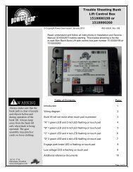
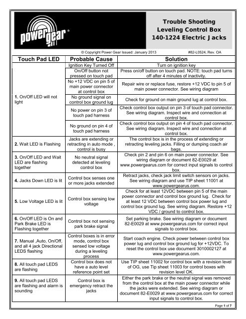
<strong>Trouble</strong> <strong>Shooting</strong><strong>Leveling</strong> <strong>Control</strong> <strong>Box</strong><strong>140</strong>-<strong>1224</strong> Electric Jacks© Copyright <strong>Power</strong> <strong>Gear</strong> Issued: January 2013 #82-L0524, Rev. OATouch Pad LED Probable Cause Solution1. On/Off LED will notlight2. Wait LED is Flashing3. On/Off LED and WaitLED are flashingtogether4. Jacks Down LED is lit5. Low Voltage LED is lit6. On/Off LED is On andPark Brake LED isFlashing together7. Manual ,Auto, On/Off,and all 4 jack DirectionalLEDS flashing8. All touch pad LEDSare flashing9. All touch pad LEDSare flashing and alarm issoundingIgnition Key Turned OffOn/Off button notpressed on touch padNo +12 VDC on pin 5 ofmain power connectorat control boxNo ground signal oncontrol box ground lugNo power on pin 3 oftouch pad harnessNo ground on pin 4 oftouch pad harnessJacks are extending orretracting in auto mode ,control is busyNo neutral signaldetected at levelingcontrol box<strong>Control</strong> box senses oneor more jacks extended<strong>Control</strong> box sensing lowvoltage<strong>Control</strong> box not sensingpark brake signal<strong>Control</strong> boxes is in errormode, control boxsensed low voltageduring a levelingprocess<strong>Control</strong> box does nothave a auto levelreference point set<strong>Control</strong> box isemergency retract thejacksTurn on ignition keyPress on/off button on touch pad. NOTE: touch pad turnsoff after 4 minutes of inactivity.Repair wire or replace fuse, restore +12 VDC to pin 5 ofmain power connector. See wiring diagramCheck for ground on main ground lug at control box.Check control box output on pin 3 of touch pad connector.See wiring diagram. Inspect wire and connection atcontrol box.Check control box output on pin 4 of touch pad connector.See wiring diagram. Inspect wire and connection atcontrol box.The control box is in the process of extending orretracting leveling jacks. Filling or dumping coach airbags.Check pin 2 and pin 6 on main power connector. Seewiring diagram or document 82-E0029 atwww.powergearus.com for correct input signals to controlbox.Retract jacks, check jack limit switch sensors on jacks.See wiring diagram and use TIP sheet 11001 atwww.powergearus.com.Check for at least 12VDC between pin 5 of the mainpower connector and control box ground lug. Check forat least 12 VDC between control box power lug andcontrol box ground lug. See wiring diagram. Restore +12VDC / ground to control box.Set parking brake. See wiring diagram or document82-E0029 at www.powergearus.com for correct inputsignals to control box.Start coach engine. Check power between control boxpower lug and control box ground lug for +12VDC. Toreset the control box use document 3010002127 atwww.powergearus.com.Use TIP sheet 11002 for control box with a revision levelof OG, use Tip sheet 11003 for control boxes withrevision level OK.Either the park brake or the neutral signal was removedfrom the control box at the main power connector whilethe jacks were extended. See wiring diagram ordocument 82-E0029 at www.powergearus.com for correctinput signals to control box.Page 1 of 7
82-L0524 <strong>Trouble</strong> <strong>Shooting</strong> <strong>Leveling</strong> <strong>Control</strong> <strong>Box</strong> <strong>140</strong>-<strong>1224</strong>Touch Pad LED Probable Cause Solution10. Manual, Auto andTwo Directional LEDSFlashingJack motor drawinghigher than15amps DCJack motor brakedefectiveJack motor harness isbroken or shorted outJack limit switch sensorharness is broken orshorted outJack limit switch harnessplug into wrong jackJack motor harnessplugged into the wrongport at control boxLoose connection onjack motor harnessLoose connection onjack limit switch sensorharnessTest jack motor per document 82-L0501 atwww.powergearus.com. NOTE: Jack motor normaloperating amp draw is 4-8 amps DC.Inspect / Replace jack brake per document3010001428 at www.powergearus.com. NOTE: Jackmotor normal operating amp draw is 4-8 amps DC.Inspect / test jack motor harness. Replace wiringharness. See wiring diagram.Inspect / test jack limit switch harness. Replacewiring harness. See wiring diagram. Use TIP sheet11001 at www.powergearus.com.Verify that correct jack limit switch harness is pluggedinto correct jack. See wiring diagram.Verify that the correct jack motor harness is pluggedinto the correct control box port.Verify that jack motor harness connections at jackassembly and control box are seated properly andmaking good contact. See Wiring diagram.Verify that jack limit switch sensor harnessconnections at jack assembly and control box areseated properly and making good contact. See Wiringdiagram.Page 2 of 7
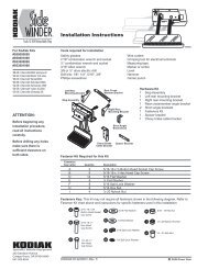
82-L0524 <strong>Trouble</strong> <strong>Shooting</strong> <strong>Leveling</strong> <strong>Control</strong> <strong>Box</strong> <strong>140</strong>-<strong>1224</strong>213<strong>140</strong>-<strong>1224</strong> <strong>Control</strong> <strong>Box</strong>74859610Item #1-Auxiliary Harness ConnectorPin#1 Fill output to the airbag valve. Energized with+12vdc to fill airbags.Pin#2 Fill output to the airbag valve. Ground to fillairbags.Pin#3 Dump output to the airbag valve. Energizedwith +12vdc to dump airbags.Pin#4 Dump output to the airbag valve. Ground todump airbags.Item #2- Limit Switch ConnectorItem #3-V Battery LugPin #1 Input +12vdc from batteryItem #4-Touch Pad Harness ConnectorPin #1 Output to the touch pad.Transmit signal 5-7vdc.Pin #2 Input from the touchpad.Receive signal 5-7vdc.Pin #3 <strong>Power</strong> (+12vdc) output tothe touch pad.Pin #4 Ground output to thetouchpad.Pin#1 Output 12vdc to limit switchesPin#2 Input left front limit switchPin#3 Input right front limit switchPin#4 Input left rear limit switchPin#5 Input right rear limit switchPin#6 Output ground to limit switchesItem #5-Left Front Jack Motor ConnectorPin#1 Output to jack motorPin#2 Output to jack motorNote: Pin #1 and pin #2 change polaritiesdepending on jack extending or retracting.Page 3 of 7
82-L0524 <strong>Trouble</strong> <strong>Shooting</strong> <strong>Leveling</strong> <strong>Control</strong> <strong>Box</strong> <strong>140</strong>-<strong>1224</strong>Item #6-Right Front Jack Motor ConnectorPin#1 Output to jack motorPin#2 Output to jack motorNote: Pin #1 and pin #2 changepolarities depending on jackextending or retracting.Item #8-Left Rear Jack Motor ConnectorPin#1 Output to jack motorPin#2 Output to jack motorNote: Pin #1 and pin #2 changepolarities depending on jackextending or retracting.Item #7- Main <strong>Power</strong> ConnectorItem #9-Right Rear Jack Motor ConnectorPin#1Pin#2Pin#3Pin#4Pin#5Pin#6Input from park brake. Has continuityto ground when the park brake isengaged.Input from neutral safety switch. Canmeasure as either +12vdc or ground.Not used.Not used.Input from ignition. Energized with+12vdc when the coach is running.Input from neutral safety switch. Canmeasure as either +12vdc or ground.Pin#1 Output to jack motorPin#2 Output to jack motorNote: Pin #1 and pin #2 changepolarities depending on jackextending or retracting.Item #10-Ground LugPin #1 Input Ground from chassisPage 4 of 7
Wiring DiagramPage 5 of 7
Wiring Diagram ContinuedPage 6 of 7
82-L0524 <strong>Trouble</strong> <strong>Shooting</strong> <strong>Leveling</strong> <strong>Control</strong> <strong>Box</strong> <strong>140</strong>-<strong>1224</strong>Additional reference Publication located atwww.powergearus.com82-L0368 Operators manual for electric leveling control box <strong>140</strong>-<strong>1224</strong> rev OK82-L0501 Testing the electric jack motor brake11001 Electric leveling Sensor circuit function check11002 Electric leveling installation and calibration of control box <strong>140</strong>-<strong>1224</strong> rev OG11003 Electric leveling installation and calibration for control box <strong>140</strong>-<strong>1224</strong> rev OK3010000914 Electric leveling calibration of control box <strong>140</strong>-<strong>1224</strong> rev OK3010001163 Replacement of electric leveling jack motor3010001428 Electric leveling motor brake kit replacement instructions3010002127 Electric jack error mode resetting procedure3010002134 Replacement of the electric leveling jack drive pin using pin kit 10100018893010002151 Low voltage indication for hydraulic and electric leveling controlsPage 7 of 7