Wiring Installation Instructions
Wiring Installation Instructions
Wiring Installation Instructions
- No tags were found...

Create successful ePaper yourself
Turn your PDF publications into a flip-book with our unique Google optimized e-Paper software.
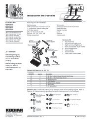
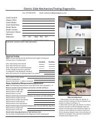
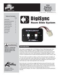
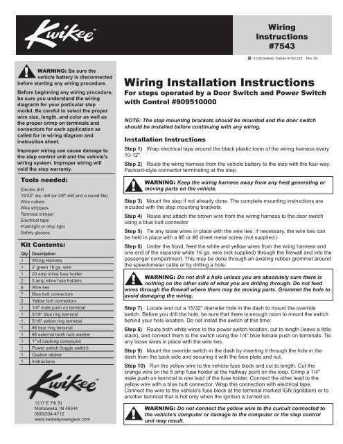
<strong>Wiring</strong><strong>Instructions</strong>#754301/05 Kwikee Kwikee #1421225 Rev. 0AWARNING: Be sure thevehicle battery is disconnectedbefore starting any wiring procedure.Before beginning any wiring procedure,be sure you understand the wiringdiagrarm for your particular stepmodel. Be careful to select the properwire size, length, and color as well asthe proper crimp on terminals andconnectors for each application ascalled for in wiring diagram andinstruction sheet.Improper wiring can cause damage tothe step control unit and the vehicle'swiring system. Improper wiring willvoid the step warranty.Tools needed:Electric drill15/32" dia. drill (or 3/8" drill and a round file)Wire cuttersWire strippersTerminal crimperElectrical tapeFlashlight or drop lightSafety glassesKit Contents:Qty Description1 <strong>Wiring</strong> Harness1 2' green 16 ga. wire1 20 amp inline fuse holder2 5 amp inline fuse holders8 Wire ties7 Blue butt connectors2 Yellow butt connectors1 1/4" male push on terminal1 5/16" blue ring terminal1 5/16" yellow ring terminal1 #6 blue ring terminal1 #6 external tooth lock washer1 1" of caulking compound1 Power switch (toggle switch)1 Caution sticker1 <strong>Instructions</strong>1217 E 7th StMishawaka, IN 46544(800)334-4712www.kwikeepowergear.com<strong>Wiring</strong> <strong>Installation</strong> <strong>Instructions</strong>For steps operated by a Door Switch and Power Switchwith Control #909510000NOTE: The step mounting brackets should be mounted and the door switchshould be installed before continuing with any wiring.<strong>Installation</strong> <strong>Instructions</strong>Step 1) Wrap electrical tape around the black plastic loom of the wiring harness every10-12".Step 2) Route the wirng harness from the vehicle battery to the step with the four-wayPackard-style connector terminating at the step.WARNING: Keep the wiring harness away from any heat generating ormoving parts on the vehicle.Step 3) Mount the step if not already done. The complete mounting instructions areincluded with the step mounting brackets.Step 4) Route and attach the brown wire from the wiring harness to the door switchusing a blue butt connectorStep 5) Tie any loose wires in place with the wire ties. If necessary, the wire ties canbe held in place with a #6 or #8 sheet metal screw (not supplied.)Step 6) Under the hood, feed the white and yellow wires from the wring harness andone end of the separate white 16 ga. wire (not supplied) through the firewall and into thepassenger compartment. This may be done through an existing rubber grommet aroundthe speedometer cable or by drilling a hole.WARNING: Do not drill a hole unless you are absolutely sure there isnothing on the other side of what you are drilling through. Do not feedwires through the firewall where there may be moving parts. Grommet the hole toavoid damaging the wiring.Step 7) Locate and cut a 15/32" diameter hole in the dash to mount the overrideswitch. Before you drill the hole, be sure that there is enough room to mount the switchbehind your hole location. Do not install the switch at this time.Step 8) Route both white wires to the power switch location, cut to length (leave a littleslack), and connect them to the switch using the 1/4" blue female push on terminals. Tieany loose wires in place with the wire ties.Step 9) Mount the override switch in the dash by inserting it through the hole in thedash from the back side and securing it with the face plate and nut.Step 10) Run the yellow wire to the vehicle fuse block and cut to length. Cut theorange wire on the 5 amp fuse holder at the halfway point on the loop. Crimp a 1/4"male push on terminal to one lead of the fuse holder. Connect the other lead to theyellow wire with a blue butt connector. Wrap this connection with electrical tape.Connect the wire to the vehicle's fuse block at the terminal marked IGN (ignitition) or toanother temrinal that is hot only when the ignition is turned on.WARNING: Do not connect the yellow wire to the curcuit connected tothe vehicle's computer or damage to the computer or the step controlunit may result.
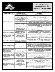
<strong>Wiring</strong> <strong>Instructions</strong> #7543 Page 2Step 11) Under the hood, run the otherend white 16 ga. wire from the overrideswitch to the battery location. Cut both thewhite and red wires to length.Step 12) Cut the orange wire on theremaining 5 amp fuse holder at themidway point of the loop. Crimp a blue5/16" ring terminal to one lead of the fuseholder. Connect the other lead to thewhite wire with a blue butt connector.Wrap this connection with electrical tape.Step 13) Cut the wire loop on the 20amp fuse holder at the midway point ofthe loop. Crimp a yellow 5/16" ringterminal to one lead to the red wire fromthe wiring harness with a yellow buttconnector. Wrap this connection withelectrical tape.Figure 1Step <strong>Wiring</strong>Fuse blockIMPORTANT:The yellow wire must go to aterminal marked IGN (ignition)or to another terminal that is hotwhen the ignition is turned on.12 AWG green ground wiremust be securely attached tothe chassis for step to operateTwo-wayconnector16 AWG purpleoptional step light switchmay be connectedto porch light6 amp maximum fuse orcircuit breaker requiredMotorassemblyUnderstep light(not available onall step models)Four-wayconnector16 AWG brown16 AWG yellow12 AWG red16 AWG white12 AWG greenground to step topControl unit(black)Step 14) Connect the red and whitewires to the positive (+) battery terminalclamping bolt.NOTE: Some vehicles have adistribution block located near thebattery that is connected directly to thebattery. The red and white wires maybe connected here instead of thebattery clamping bolt.WARNING: Do not connectthis wire into any othercircuit in the vehicle. Tie anyloose wires in place with the wire ties.Chassisground12 volt DCbatteryVehicle <strong>Wiring</strong>20 amp fuse orcurcuit breaker requiredTest Step OperationBatterydisconnectbox/switchIMPORTANT:If the switch is'OFF' the stepwill notoperate.Normally OPENmagnetic door switch5 amp maximum fuse orcircuit breaker (not supplied)Chassis groundOverrideswitchStep 15) At the step, attach the four-wayPackard-style connector from the wiringharness to the connector from the stepcontrol unit.Step 16) Reconnect the vehicle battery.Step 17) Place the "Caution - StandClear" sticker on the outside of the van onthe window glass or near the door handlewhere it will be easily seen.Step 18) With the override switch off, close the van door and the step should retract.Step 19) Open the door and the step should extend.Step 20) With the door open, turn on the override switch. The step should remainextended when the door is closed.Step 21) To test the ignition override system, with the step extended, the door closed,and the override switch on, turn on the vehicle ignition and start the vehicle. The stepshould retract.WARNING: When the ignition safety system goes into effect and thestep automatically retracts, do not open the door until the stepcompletely retracts. If the door is opened before the step completelyretracts and locks in the up position, the step will stop moving. The step mayonly be partially extended. Stepping on a partically extended step may causedamage to the step frame and/or the motor assembly. When the door is closedthe step will finish retracting.If the entrace door is opened at any time the step will extend or stay extended.230 Davidson AvenueCottage Grove, Oregon 97424-9545(541) 942-3888www.kwikee.com