Wiring Installation Instructions
Wiring Installation Instructions
Wiring Installation Instructions
- No tags were found...

You also want an ePaper? Increase the reach of your titles
YUMPU automatically turns print PDFs into web optimized ePapers that Google loves.
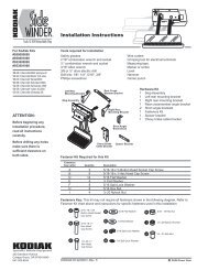
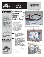
<strong>Wiring</strong> <strong>Instructions</strong> #7543 Page 2Step 11) Under the hood, run the otherend white 16 ga. wire from the overrideswitch to the battery location. Cut both thewhite and red wires to length.Step 12) Cut the orange wire on theremaining 5 amp fuse holder at themidway point of the loop. Crimp a blue5/16" ring terminal to one lead of the fuseholder. Connect the other lead to thewhite wire with a blue butt connector.Wrap this connection with electrical tape.Step 13) Cut the wire loop on the 20amp fuse holder at the midway point ofthe loop. Crimp a yellow 5/16" ringterminal to one lead to the red wire fromthe wiring harness with a yellow buttconnector. Wrap this connection withelectrical tape.Figure 1Step <strong>Wiring</strong>Fuse blockIMPORTANT:The yellow wire must go to aterminal marked IGN (ignition)or to another terminal that is hotwhen the ignition is turned on.12 AWG green ground wiremust be securely attached tothe chassis for step to operateTwo-wayconnector16 AWG purpleoptional step light switchmay be connectedto porch light6 amp maximum fuse orcircuit breaker requiredMotorassemblyUnderstep light(not available onall step models)Four-wayconnector16 AWG brown16 AWG yellow12 AWG red16 AWG white12 AWG greenground to step topControl unit(black)Step 14) Connect the red and whitewires to the positive (+) battery terminalclamping bolt.NOTE: Some vehicles have adistribution block located near thebattery that is connected directly to thebattery. The red and white wires maybe connected here instead of thebattery clamping bolt.WARNING: Do not connectthis wire into any othercircuit in the vehicle. Tie anyloose wires in place with the wire ties.Chassisground12 volt DCbatteryVehicle <strong>Wiring</strong>20 amp fuse orcurcuit breaker requiredTest Step OperationBatterydisconnectbox/switchIMPORTANT:If the switch is'OFF' the stepwill notoperate.Normally OPENmagnetic door switch5 amp maximum fuse orcircuit breaker (not supplied)Chassis groundOverrideswitchStep 15) At the step, attach the four-wayPackard-style connector from the wiringharness to the connector from the stepcontrol unit.Step 16) Reconnect the vehicle battery.Step 17) Place the "Caution - StandClear" sticker on the outside of the van onthe window glass or near the door handlewhere it will be easily seen.Step 18) With the override switch off, close the van door and the step should retract.Step 19) Open the door and the step should extend.Step 20) With the door open, turn on the override switch. The step should remainextended when the door is closed.Step 21) To test the ignition override system, with the step extended, the door closed,and the override switch on, turn on the vehicle ignition and start the vehicle. The stepshould retract.WARNING: When the ignition safety system goes into effect and thestep automatically retracts, do not open the door until the stepcompletely retracts. If the door is opened before the step completelyretracts and locks in the up position, the step will stop moving. The step mayonly be partially extended. Stepping on a partically extended step may causedamage to the step frame and/or the motor assembly. When the door is closedthe step will finish retracting.If the entrace door is opened at any time the step will extend or stay extended.230 Davidson AvenueCottage Grove, Oregon 97424-9545(541) 942-3888www.kwikee.com