
Create successful ePaper yourself
Turn your PDF publications into a flip-book with our unique Google optimized e-Paper software.
WARRANTYFor questions regardingthese warrantyprocedures or technicalassistance,call 1-800-736-9961.Be sure to visit usonline for updates, anddownloadabledocuments.Go to:www.kwikee.com1. We warrant that the equipment is free from defects in material and workmanshipunder normal use and service. The provisions of this warranty shall not apply to anyequipment that has been subject to misuse, negligence, alteration, accident, improperinstallation (such as the welding of the step to the vehicle frame or mounting brackets),normal deterioration due to wear, or has been repaired outside our place of business in anyway as, in our reasonable judgement, to adversely affect its performance and reliability.2. Our obligation under this warranty is limited to repairing or replacing, at our option,any product that is returned to our place of business and when in its examination shalldisclose to our reasonable satisfaction that it is defective. The repair or replacement of thedefective parts under this warranty will be made without charge for parts or labor.Shipping charges for returning parts to Kwikee Products Company, Inc. (“Kwikee”) shallbe the responsibility of the customer. Kwikee will pay shipping charges when returningwarrantable parts to the customer. Kwikee will not accept C.O.D. shipments of anyreturned goods.3. The warranty is effective as of the date of sale to the original purchaser and extendstwo years for parts and labor on step mechanisms and one year for step finish. Since it isthe responsibility of the owner to verify the original purchase date, Kwikee recommendsthat a bill of sale or sales receipt be kept for that purpose.4. The duration of any implied warranty of merchantability or fitness for a particularpurpose shall be limited in all respects to the duration of the limited warranty, and thewarranty described above shall be in lieu of any other express warranty. Some states donot allow limitations on how long implied warranties last, so the above limitations maynot apply to you. We neither assume or authorize any other persons to assume any otherliability in connection with our products.5. The buyer’s sole and exclusive remedy against the seller shall be for the repair orreplacement of defective merchandise as provided above. No other remedy, including butnot limited to, incidental or consequential damages for lost profits, lost sales, injury toproperty or any other incidental or consequential loss, shall be available to him. Somestates do not allow the exclusion or limitation of incidental or consequential damages, sothe above limitation or exclusion may not apply to you. Before using, user shall determinethe suitability of the product for its intended use, and user assumes all risk and liabilitywhatsoever in connection there with.6. Kwikee will not, under any circumstances, reimburse the cost of warranty partspurchased from sources other than Kwikee Products Company, Inc.7. This warranty gives you specific legal rights, and you may have other rights whichvary from state to state.WARRANTY GUIDELINES AND PROCEDURES1. Replace only those parts that are actually defective. Motors, gear cases, gears,linkage assemblies, and control units are all replaceable as individual parts. If youexchange a complete assembly when only the replacement of an individual part isrequired, the non-defective parts will be returned and only the defective part will becredited to you or replaced.2. Do not use conversion kits for warranty repairs. Conversion kits are intended for theconversion of older steps with field-wound motors to the newer permanent magnet motorsystem.3. A Returned Goods Authorization (RGA) number must be obtained before any partsor claims are sent in. Call Kwikee's Service Line at 1-800-736-9961 for an RGA number.4. Our warranty does not cover travel time, mileage, or other incidental costs. It islimited solely to the replacement of defective parts under warranty.Page 2 / WarrantyKwikee <strong>42</strong> <strong>Series</strong> <strong>Step</strong>
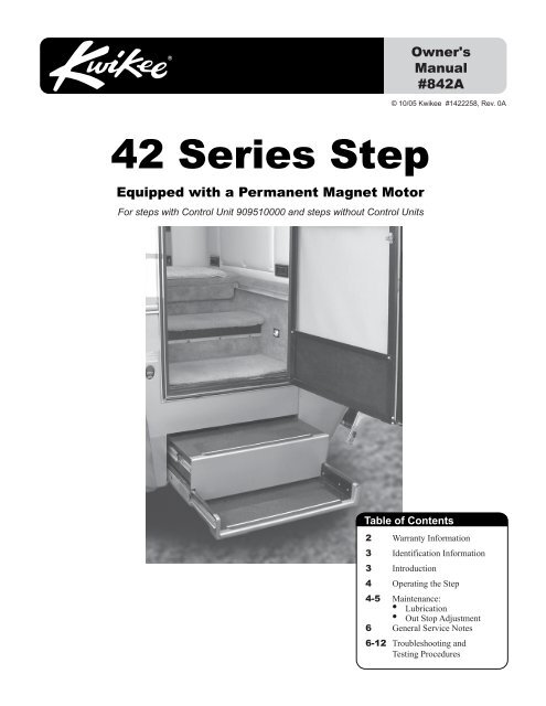
FILL OUT AND SAVE WITH VEHICLE RECORDSIn the event that servicing the step becomes necessary, the information that you supply belowwill improve service response time. The <strong>Step</strong> <strong>Series</strong> number, Serial number, and Control Unitnumbers are on the identification labels attached to the control unit and the underside of thestep, near the motor. Please take a moment to record this information:<strong>Step</strong> Serial #<strong>Step</strong> <strong>Series</strong> #STEPIDENTIFICATIONANDREPLACEMENTPARTSINFORMATIONYear / Make / Model of RVDate of PurchaseCONTROL UNIT Complete the following only if your step is equipped with Control Unit.Control Unit Serial # Control Unit #This manual has been provided to assist you with the identification, operation,maintenance, and troubleshooting of any Kwikee electric step that is equipped with a doorswitch, an override switch, control unit and a permanent magnet motor. It does not applyand should not be used as a reference to any other previous versions of a Kwikee electricstep.INTRODUCTIONThe control unit is essentially a current sensor as well as a switching device. When themotor assembly moves the step tread to its extended position, or stops moving because ofan obstruction such as a curb or the binding of a damaged or bent step frame, the motordraws a larger amount of current. The control unit “senses” the larger current draw andshuts off power to the motor.All control units are equipped with an "ignition override system". This system is designedso that the vehicle will not be driven with the step in the extended position. When the stepis overriden in the extended position, the door closed, and the ignition is turned on, theignition override system will engage and the step will automatically retract.The “AutoExtend” feature is another safety feature designed to extend the step when thedoor is opened for the first time after the vehicle ignition is turned off, even if the overrideswitch is turned on. When the ignition is switched on, the function of the override switch isdisabled and the step will always extend when the door is opened and retract when the dooris closed.NOTE: Follow the instructions in this manual carefully. Failure to do so may resultin damage to the step control, the motor and/or the vehicle wiring. Such damagemay also result in voiding the warranty.Owner's Manual <strong>Step</strong> Identification and Replacement Parts Information / Page 3
OPERATION1. After the installation is complete and with the entrance door open, turn the overrideswitch 'off.'NOTE: Some steps are not equipped with a override switch. They are activatedonly with a door switch.2. Close the door. The step should retract and lock in the "in" position.3. Open the door. The step should extend and lock in the "out" position.WARNING: If the vehicleis driven with the step inthe extended position,there is the possibilityof causing majordamage to both the stepand the vehicle.4. If your step is equipped with an override switch, turn it 'on.' The step shouldremain in the extended position when the door is closed.5. With the override switch 'on,' the step extended, and the entrance doorclosed, turn 'on' the vehicle ignition. The ignition override system will go intoeffect and the step will automatically retract.NOTE: If the yellow wire from the four-way connector is not connected to anignition power source, the ignition safety system will be inoperative and the stepwill remain in the extended position. In this case, the override switch must beturned 'off' for the step to retract.6. Turn the vehicle ignition 'off' and open the door. The step will extend and lock in the"out" position. This is the "AutoExtend" feature.When the vehicle ignition is 'on,' the step will always activate with the door movement,regardless of the override switch position.NOTE: If the yellow wire from the four-way connector is not connected to anignition power source, the step will not retract with the step in the override 'on'position when the door is closed and the ignition is 'on.'MAINTENANCEFIGURE 1 Power wash and spray dry lubricant on bearings onboth sides of step.LUBRICATION1. Clean all mud, salt, and road grime from the stepbefore lubricating. Power wash and spray dry lubricant onthe bearings (see Figure 1.)NOTE: Silicone lubricants and WD-40 are notrecommended as they have a tendency to evaporateand dry the mating surfaces which leave themvulnerable to the elements.2. Maintain clean, dry electrical connections at thetwo-way and four-way connectors and any buttconnections leading from the four-connector to thevehicle. A small dab of di-electric grease at theconnections and replacing corroded butt connections withheat shrink type crimp style automotive connectors willhelp maintain a good electrical source for the step.Page 4 / IntroductionKwikee <strong>42</strong> <strong>Series</strong> <strong>Step</strong>
ADJUSTING THE OUT STOPSKwikee steps are fitted with adjustable out stops on the step frame that help lockthe step in the "out" position, creating a firm stepping platform. The out stop isadjusted at the factory but due to the rigors of shipping, installation, andnormal use the stop may fall out of adjustment and need to be tightened.1. Loosen the stops so they move freely andretract the step.2. Extend the step fully to its locked extendedposition. Be sure that the motor assembly linkagerests against the steel plate as illustrated in Figure 2.Repeat if needed until the motor assembly locks inthe extended position.CAUTION: Whenworking under the step,be sure that the stepcannot be activated andthat nothing can getcaught in the stepmechanism.WARNING: When thestops are out ofadjust-ment, the stepmay feel loose whenstepped on.3. Push the stops against the lower tread and tighten securely. Be sure that both stops aretightened and that they rest securely against the lower tread.4. Retract the step. Check to be sure that both stops are secure against the top tread (seeFigure 3.) Repeat the above procedures if needed to properly adjust the stops.CAUTION: Be sure thatnothing can get caughtin the step mechanism.FIGURE 2BottomFIGURE 3TopSecure againsttop treadAdjustretractionof stepSteelPlateAdjustextensionof stepSecure againstlower treadOwner's Manual Operation / Page 5
GENERALSERVICE NOTESThese general servicenotes and the <strong>Step</strong>Test Proceduresaddress the mostcommon questionsabout Kwikee electricsteps. Due to thenumber of variableconditions, you mayexperience symptomsother than thosecovered. Please feelfree to contact theCustomer ServiceDepartment at1-800-736-9961 forfurther information orassistance.If the power wire to the step is disconnected from its source and reconnected, a spark iscommon. This is caused by the momentary charging of the control unit and does notnecessarily indicate the system is staying on, which would cause a drain on the battery. Ifbattery drain is suspected, observe the understep light (if so equipped) while the step isextending. The override switch must be 'off' for the understep light to operate.To determine if a control unit is not shutting off, remove the four-way connector to thechassis and the two-way connector between the step motor and the contol unit. Place avoltmeter between the red and yellow motor wires at the two-way connector from thecontrol unit. Reconnect the four-way Connector. Turn the override switch 'on.' If anyvoltage registers on the meter for more than 5 seconds, the control unit is not shutting offand may be defective. When doing this test, switch the voltmeter leads back and forthbetween the red and yellow motor wires to be sure no voltage registers.If any voltage does register, disconnect the four-way connector to keep the step motor fromoverheating. If zero voltage is present, the control unit has shut off and is normal.If the step does not work or operates erratically, such as extending part way and shutting'off,' the first item that should be checked is the vehicle’s battery. Low supply voltage maycause erratic operation of the step. Poor ground connections may also cause erraticoperation of the step. Check battery voltage and condition. A battery in good condition andproperly charged will have a no load voltage of approx. 12.6 volts. Check the voltage at thebattery and at the four-way connector at the control unit. Insure that all battery and stepcontrol unit connections are clean and secure. Recharge or replace the battery as necessaryand retest the step for proper operation.The step may also operate erratically if the step is being operated directly from a converter,and the output from the converter is not adequate or properly filtered for clean DC voltage.The converter must be capable of producing a minimum of 30 amps for proper stepoperation.If the ground to the control unit is lost, either between the step control unit and the vehiclechassis (the long green ground wire) or between the vehicle battery and the ground(negative battery cable) the step will not function. Make sure the battery terminals and allwire connections are clean and tight. Verify that all wires meet the minimum requirementsspecified in Figures 4 and 5 on Page 8.TROUBLESHOOTINGAND TESTINGPROCEDURESThe following <strong>Step</strong> Test Procedures have been provided to troubleshoot and test all of theKwikee automatic electric step functions. They are designed to initially check the step'sbasic functions separately from the RV wiring to determine whether or not the step ismalfunctioning. The following procedures test the various components of the step until thesource of the malfunction is located. Using these procedures will shorten and reduce thetime spent troubleshooting.Some portions of the test procedures require additional equipment. This equipmentincludes: a voltmeter, a well charged 12 volt DC automotive battery, and a 4-wayconnector/pigtail (Part #909306000, available from Kwikee Products Company).Read the entire procedure prior to testing. If you need assistance contact Kwikee’sService Line at 1-800-736-9961.Page 6 / MaintenanceKwikee <strong>42</strong> <strong>Series</strong> <strong>Step</strong>
TESTING THE STEP1. Inspect the step for visible damage that might restrict the step’s operation.2. Obtain a 4-way pigtail connector (part #909306000) from Kwikee.WARNING: Keep fingers,arms, and legs clear ofstep mechanism whileperforming these tests.3. Disconnect 4-way connector on underside of step and connect step-half of theconnector to the four-way connector pigtail. See Figures 4 and 5 on Pages 8 and 9.4. Set a fully charged 12 volt DC automotive battery beside the step.ATTENTION: Do not allow the battery terminals to come in contact with step.Complete a ground for step testing by connecting 10 gauge wire from the negative ( _ )battery post to the green ground wire of the control unit.5. To supply power, attach the red wire from pigtail to positive (+) post. The step willextend.6. With the power and ground connections complete, all functions of thecontrol unit can be checked at the four wires of the pigtail. The brown wireis the door switch, the white wire is the override switch, and the yellow wireis the ignition override.7. To retract the step, touch the brown wire to the negative ( _ ) terminal.8. To extend the step, remove the brown wire from the battery's negative (-) post.WARNING: 12 voltautomotive batteriescontain sulfuric acidwhich can causesevere burns. Avoidcontact with the skin,eyes and clothing. 12volt automotivebatteries producehydrogen gas which isexplosive; keepcigarettes, openflames and sparksaway from the batteryat all times.IMPORTANTINSTALLER NOTES:Be sure that all groundconnections are securely fastenedwith good metal-to-metal contact.A good ground is required forproper step operation.Owner's Manual Maintenance / Page 7
FIGURE 4: Wiring diagram for step with control unitFuse blockIMPORTANT:The yellow wire must go to aterminal marked IGN (ignition)or to another terminal that is hotwhen the ignition is turned on.Chassisground12 volt DCbatteryVehicle Wiring20 amp fuse orcurcuit breaker required6 amp maximum fuse orcircuit breaker requiredBatterydisconnectbox/switchIMPORTANT:If the switch is'OFF' the stepwill notoperate.<strong>Step</strong> Wiring16 AWG purpleoptional step light switchmay be connectedto porch light(see Inset 4A)12 AWG greenground to step topControlunitNormally OPENmagnetic door switchFour-wayconnector16 AWG brown16 AWG yellow12 AWG red16 AWG white5 amp maximum fuse orcircuit breaker (not supplied)ChassisgroundPowerswitchNot used12 AWG green ground wiremust be securely attached tothe chassis for step to operateMotorassemblyTwo-wayconnectorINSET 4A - Wiring step light toporch light switch: Understep light can bewired directly to the RV porch light switch. If youchoose to do this, a 5 amp maximum fuse orcircuit breaker is required and can be installedin either of two locations as shown in thewiring diagram below.Fuse location1 amp maxor circuit breakerrequired(not supplied)ToBatteryBattery disconnectbox/switchIMPORTANT: If theswitch is 'OFF' thelight will not operate.Porch light switchAlternatefuse locationPorch lightButt connector<strong>Step</strong> LightControl UnitPurple wirefrom Control Unit9. To test the Ignition Override feature, extend the step as in <strong>Step</strong> 8. With the stepextended, connect the white wire to the battery's positive (+) terminal and attach the brownwire to the battery's negative ( _ ) terminal. Next, touch the yellow wire to the battery'spositive (+) terminal. The step should retract. Remove the brown wire and the step shouldextend.10. To test the Override Switch, with the step retracted, touch the brown wire to thenegative ( _ ) terminal to retract the step. While holding the brown wire to the negative ( _ )terminal, touch the shite wire to the battery's positive (+) terminal, and remove the yellowfrom the positive (+) terminal. The <strong>Step</strong> will stay retracted. Now, remove the brown wire.The step should extend. Now touch the brown wire to the battery's negative (-) terminaland the step should stay extended.11. If any of the step functions do not work, the source of the malfunction is either inthe control unit and/or the motor. Proceed to the "Testing the Motor" section on Page 9.If all of the step functions do work, the malfunction is either in the door switch, powerswitch, or the vehicle wiring. Proceed to "Testing the 4-way Connector" section.Page 8 / General Service NotesKwikee <strong>42</strong> <strong>Series</strong> <strong>Step</strong>
FIGURE 5: Wiring diagram for steps with door switch only operation<strong>Step</strong> Wiring16 AWG purpleoptional step light switchmay be connectedto porch light(see Inset 5A)12 AWG greenground to step topControlunitNot used12 AWG green ground wiremust be securely attached tothe chassis for step to operateTwo-wayconnectorChassisground12 volt DCbatteryVehicle Wiring20 amp fuse orcurcuit breaker requiredBatterydisconnectbox/switchIMPORTANT:If the switch is'OFF' the stepwill notoperate.16 AWG brown12 AWG redChassisgroundNormally OPENmagnetic door switchFour-wayconnectorMotorassemblyINSET 5A - Wiring step light toporch light switch: Understep light can bewired directly to the RV porch light switch. If youchoose to do this, a 5 amp maximum fuse orcircuit breaker is required and can be installedin either of two locations as shown in thewiring diagram below.Fuse location1 amp maxor circuit breakerrequired(not supplied)ToBatteryBattery disconnectbox/switchIMPORTANT: If theswitch is 'OFF' thelight will not operate.Porch light switchAlternatefuse locationPorch lightButt connector<strong>Step</strong> LightControl UnitPurple wirefrom Control UnitTESTING THE MOTOR1. Disconnect the two-way connector between the step motor and the control unit.Connect the motor’s yellow wire to the positive (+) terminal of the battery and touch themotor’s red wire to the negative ( _ ) terminal of the battery to extend the step. To retract thestep, reverse the connections. If the step extends and retracts during this test, the conditionof the step motor is good.TESTING THE 4-WAY CONNECTOR1. To check the main power source, connect a voltmeter between the red wire from the4-way connector (vehicle half) and the ground terminal at the end of the control unit’sgreen ground wire (see Figure 6 on Page 9). The reading should be a minimum of 12volts DC.If the voltage reading is low, there may be a loose or corroded connection at the battery, alow charge level on the battery itself, or a poor ground. If the voltage reading is zero (0)Owner's Manual Troubleshooting and Testing Procedures / Page 9
volts, check the step fuse/circuit breaker, all connections, and the condition of the wiringbetween the battery and the plug, including the ground connection at the chassis.WARNING: Do not leavethe wires connectedduring this test oncethe step has cycledeither in or out. Failureto remove the wiresfrom the battery willburn out the motorvoiding any warranty.2. To check the override switch, connect a voltmeter between the white wire from the4-way connector (vehicle half) and the terminal at the end of the control unit’s greenground wire (see Figure 7). The reading should be a minimum of 12 volts DC (the sameas in <strong>Step</strong> 1) when the switch is on, and zero (0) volts DC when the switch is off.If the voltmeter reads zero (0) volts when the override switch is on, there is a problemin the override switch circuit.Check the 6 amp in-line fuse, the override switch itself and the condition of thecircuit’s wiring and terminal connections.3. To check the door switch, connect a voltmeter between the red wire from the4-way connector (vehicle half) and the brown in the same connector (see Figure 8) onPage 11). The voltage should be a minimum of 12 volts DC (the same as in <strong>Step</strong> 1) whenthe door is closed and zero (0) volts when the door is open.If the readings are incorrect, there is a problem with the switch. Check the door switch andthe condition of the circuit's wiring and terminal connections.FIGURE 6: Check power source4-way connector(vehicle-side)RedGround wire: green ground wiremust be attached to vehiclechassis; a good ground is neededfor proper step operationVoltmeter shouldread 12 volts DCPage 10 / Troubleshooting and Testing ProceduresKwikee <strong>42</strong> <strong>Series</strong> <strong>Step</strong>
FIGURE 7: Check override switch4-way connector(vehicle-side)WhiteFIGURE 8: Check door switch4-way connector(vehicle-side)RedBrownGround wire: green ground wiremust be attached to vehiclechassis; a good ground is neededfor proper step operationVoltmeter should read12 volts DC when dooris closedVoltmeter should read12 volts DC / override 'on'0 volts DC / override 'off'Voltmeter should read0 volts DC when dooris openFIGURE 9: Check ignition overrideFIGURE 10: Check connector4-way connector(vehicle-side)Yellow4-way connector(vehicle-side)RedBrownGround wire: green ground wiremust be attached to vehiclechassis; a good ground is neededfor proper step operationGround wire: green ground wiremust be attached to vehiclechassis; a good ground is neededfor proper step operationVoltmeter should read12 volts DC / ignition 'on'0 volts DC / ignition 'off'Voltmeter shouldread 0 volts DCOwner's Manual Troubleshooting and Testing Procedures / Page 11
4. To check the ignition override system, connect a voltmeter between the yellow wirefrom the 4-way connector (vehicle half) and the ground terminal on the end of the controlunit’s green ground wire (see Figure 9.) The voltage reading should be approximately 12volts DC when ignition is on and zero (0) volts when ignition is off.If the reading is zero when the ignition is on, check all terminal connections, wiring, andthe vehicle's ignition fuse.NOTE: The step wiring circuit must be independent. No other device (i.e. alarmsystems, step well lights, etc.) can be connected to the step wiring circuit. Anydevice connected to the steps wiring can cause the step to malfunction and willvoid the warranty.5. For steps equipped with door switch only operation: Connect the white jumper wirefrom the vehicle half of the four-way connector and the ground terminal at the end of thecontrol unit’s green ground wire (see Figure 10).NOTE: Be sure to use the terminal with only the white wire.The reading should be 0 volts DC. If the voltage reading is more, the white wire isconnected to 12 volts and should be cut.If you have additional questions or need more assistance, contact Kwikee’s ServiceRepresentative at 1-800-736-9961.230 Davidson Avenue, Cottage Grove, OR 97<strong>42</strong>4-9545(541) 9<strong>42</strong>-3888www.kwikee.com