You also want an ePaper? Increase the reach of your titles
YUMPU automatically turns print PDFs into web optimized ePapers that Google loves.
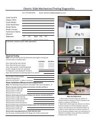
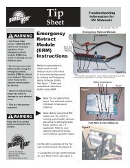
4. To check the ignition override system, connect a voltmeter between the yellow wirefrom the 4-way connector (vehicle half) and the ground terminal on the end of the controlunit’s green ground wire (see Figure 9.) The voltage reading should be approximately 12volts DC when ignition is on and zero (0) volts when ignition is off.If the reading is zero when the ignition is on, check all terminal connections, wiring, andthe vehicle's ignition fuse.NOTE: The step wiring circuit must be independent. No other device (i.e. alarmsystems, step well lights, etc.) can be connected to the step wiring circuit. Anydevice connected to the steps wiring can cause the step to malfunction and willvoid the warranty.5. For steps equipped with door switch only operation: Connect the white jumper wirefrom the vehicle half of the four-way connector and the ground terminal at the end of thecontrol unit’s green ground wire (see Figure 10).NOTE: Be sure to use the terminal with only the white wire.The reading should be 0 volts DC. If the voltage reading is more, the white wire isconnected to 12 volts and should be cut.If you have additional questions or need more assistance, contact Kwikee’s ServiceRepresentative at 1-800-736-9961.230 Davidson Avenue, Cottage Grove, OR 97<strong>42</strong>4-9545(541) 9<strong>42</strong>-3888www.kwikee.com