Replacement Transmitter Antenna Assembly Manual for the DX7 ...
Replacement Transmitter Antenna Assembly Manual for the DX7 ...
Replacement Transmitter Antenna Assembly Manual for the DX7 ...

You also want an ePaper? Increase the reach of your titles
YUMPU automatically turns print PDFs into web optimized ePapers that Google loves.
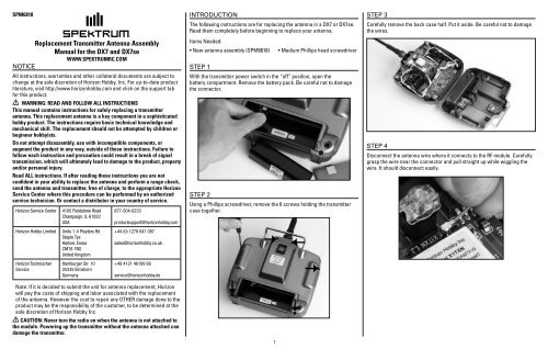
SPM6818<strong>Replacement</strong> <strong>Transmitter</strong> <strong>Antenna</strong> <strong>Assembly</strong><strong>Manual</strong> <strong>for</strong> <strong>the</strong> <strong>DX7</strong> and <strong>DX7</strong>sewww.spektrumrc.comNOTICEAll instructions, warranties and o<strong>the</strong>r collateral documents are subject tochange at <strong>the</strong> sole discretion of Horizon Hobby, Inc. For up-to-date productliterature, visit http://www.horizonhobby.com and click on <strong>the</strong> support tab<strong>for</strong> this product.WARNING: READ AND FOLLOW ALL INSTRUCTIONSThis manual contains instructions <strong>for</strong> safely replacing a transmitterantenna. This replacement antenna is a key component in a sophisticatedhobby product. The instructions require basic technical knowledge andmechanical skill. The replacement should not be attempted by children orbeginner hobbyists.Do not attempt disassembly, use with incompatible components, oraugment <strong>the</strong> product in any way, outside of <strong>the</strong>se instructions. Failure tofollow each instruction and precaution could result in a break of signaltransmission, which will ultimately lead to damage to <strong>the</strong> product, propertyand/or personal injury.Read ALL instructions. If after reading <strong>the</strong>se instructions you are notconfident in your ability to replace <strong>the</strong> antenna and per<strong>for</strong>m a range check,send <strong>the</strong> antenna and transmitter, free of charge, to <strong>the</strong> appropriate HorizonService Center where this procedure can be per<strong>for</strong>med by an authorizedservice technician. Or contact a distributor in your country of service.Horizon Service CenterHorizon Hobby LimitedHorizon TechnischerService4105 Fieldstone RoadChampaign, IL 61822USAUnits 1-4 Ployters RdStaple TyeHarlow, EssexCM18 7NSUnited KingdomHamburger Str. 1025335 ElmshornGermany877-504-0233productsupport@horizonhobby.com+44 (0) 1279 641 097sales@horizonhobby.co.uk+49 4121 46199 66service@horizonhobby.deNote: If it is decided to submit <strong>the</strong> unit <strong>for</strong> antenna replacement, Horizonwill pay <strong>the</strong> costs of shipping and labor associated with <strong>the</strong> replacementof <strong>the</strong> antenna. However <strong>the</strong> cost to repair any OTHER damage done to <strong>the</strong>product may be <strong>the</strong> responsibility of <strong>the</strong> customer, to be determined at <strong>the</strong>sole discretion of Horizon Hobby Inc.CAUTION: Never turn <strong>the</strong> radio on when <strong>the</strong> antenna is not attached to<strong>the</strong> module. Powering up <strong>the</strong> transmitter without <strong>the</strong> antenna attached candamage <strong>the</strong> transmitter.IntroductionThe following instructions are <strong>for</strong> replacing <strong>the</strong> antenna in a <strong>DX7</strong> or <strong>DX7</strong>se.Read <strong>the</strong>m completely be<strong>for</strong>e beginning to replace your antenna.Items Needed:• New antenna assembly (SPM6818) • Medium Phillips head screwdriverStep 1With <strong>the</strong> transmitter power switch in <strong>the</strong> “off” position, open <strong>the</strong>battery compartment. Remove <strong>the</strong> battery pack. Be careful not to damage<strong>the</strong> connector.Step 2Using a Phillips screwdriver, remove <strong>the</strong> 6 screws holding <strong>the</strong> transmittercase toge<strong>the</strong>r.1Step 3Carefully remove <strong>the</strong> back case half. Put it aside. Be careful not to damage<strong>the</strong> wires.Step 4Disconnect <strong>the</strong> antenna wire where it connects to <strong>the</strong> RF module. Carefullygrasp <strong>the</strong> wire near <strong>the</strong> connector and pull straight up while wiggling <strong>the</strong>wire. It should disconnect easily.
Step 5Unscrew and remove <strong>the</strong> Phillips head screw from <strong>the</strong> antenna base plateand <strong>the</strong> Phillips head screw from <strong>the</strong> antenna housing. Notice that of <strong>the</strong> 3holes in <strong>the</strong> base plate, <strong>the</strong> antenna routes through <strong>the</strong> rectangular hole.Step 7Reassemble <strong>the</strong> new antenna assembly and <strong>the</strong> shaft. Route <strong>the</strong> coaxialwire through <strong>the</strong> shaft until <strong>the</strong> wire exits <strong>the</strong> rectangular opening at <strong>the</strong>base of <strong>the</strong> shaft. Align <strong>the</strong> shaft with <strong>the</strong> antenna housing until <strong>the</strong> Phillipshead screw holes line up. Be careful not to pinch <strong>the</strong> antenna wire whenreinserting <strong>the</strong> shaft. Then install <strong>the</strong> Phillips screw on <strong>the</strong> antenna housing.Step 9Install <strong>the</strong> antenna connector on <strong>the</strong> RF module. Precise alignment isneeded so <strong>the</strong> two snap toge<strong>the</strong>r. Carefully align <strong>the</strong> connector and pressin place until it clicks. Ensure proper connection by a slight “side-to-side”movement of <strong>the</strong> antenna wire.Step 6Slide <strong>the</strong> antenna assembly out of <strong>the</strong> top of <strong>the</strong> transmitter.Step 8Install <strong>the</strong> antenna assembly in <strong>the</strong> transmitter. Feed <strong>the</strong> antenna wirethrough <strong>the</strong> rectangular opening in <strong>the</strong> metal baseplate. Make sure <strong>the</strong>key is in <strong>the</strong> non-rectangular slot. Use care not to pinch <strong>the</strong> antenna wire.Fasten it in place using <strong>the</strong> Phillips screw in <strong>the</strong> center hole.Step 10Confirm <strong>the</strong> installation was done correctly by checking that all wires,screws and o<strong>the</strong>r components are back to <strong>the</strong>ir original position with <strong>the</strong>new antenna installed. Check to ensure no wires are kinked or will bepinched when <strong>the</strong> transmitter is screwed back toge<strong>the</strong>r. Reassemble <strong>the</strong>unit and per<strong>for</strong>m a range check.Range check procedures:1. With <strong>the</strong> model resting on <strong>the</strong> ground, system powered and modelsecured, stand 30 paces (approx. 90 feet) away from <strong>the</strong> model.2. Face <strong>the</strong> model with <strong>the</strong> transmitter in your normal flying position anddepress and hold <strong>the</strong> bind button on <strong>the</strong> back of <strong>the</strong> transmitter. Thiscauses reduced power output from <strong>the</strong> transmitter.3. You should have total control of <strong>the</strong> model with <strong>the</strong> button depressedat 30 paces (90 feet).4. If control issues exist, contact <strong>the</strong> appropraite Horizon Service Center<strong>for</strong> fur<strong>the</strong>r assistance.Note: If any time during or after <strong>the</strong> installation you do not feel confidentabout <strong>the</strong> installation, please send it to <strong>the</strong> appropriate HorizonService Center.WARNING: ENSURE FUTURE ANTENNA SAFETY - Do not attempt touse <strong>the</strong> antenna to bear any weight, pick up <strong>the</strong> transmitter by <strong>the</strong> antennaor alter <strong>the</strong> antenna in any way. If <strong>the</strong> transmitter antenna or relatedcomponents become damaged <strong>the</strong> output strength can be severely impededwhich will likely lead to a crash, injury, and property damage.2©2010 Horizon Hobby, Inc., 4105 Fieldstone Road, Champaign, IL 61822 USAHorizon Hobby Limited, Units 1-4 Ployters Rd, Staple Tye, Harlow, Essex, CM18 7NS, United KingdomHorizon Hobby GmbH, Hamburger Strasse 10, 25335 Elmshorn, GermanyThe Spektrum trademark is used with permission of Bachmann Industries, Inc. Updated 5/10 27877.1