AKRAPOVIC RACING & EVOLUTION EXHAUST ... - Akrapovic Auspuff
AKRAPOVIC RACING & EVOLUTION EXHAUST ... - Akrapovic Auspuff
AKRAPOVIC RACING & EVOLUTION EXHAUST ... - Akrapovic Auspuff

You also want an ePaper? Increase the reach of your titles
YUMPU automatically turns print PDFs into web optimized ePapers that Google loves.
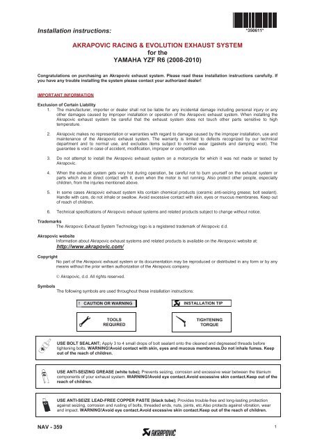
Installation instructions:*350611*<strong>AKRAPOVIC</strong> <strong>RACING</strong> & <strong>EVOLUTION</strong> <strong>EXHAUST</strong> SYSTEMfor theYAMAHA YZF R6 (2008-2010)Congratulations on purchasing an <strong>Akrapovic</strong> exhaust system. Please read these installation instructions carefully. Ifyou have any trouble installing the system please contact your authorized dealer!IMPORTANT INFORMATIONExclusion of Certain Liability1. The manufacturer, importer or dealer shall not be liable for any incidental damage including personal injury or anyother damages caused by improper installation or operation of the <strong>Akrapovic</strong> exhaust system. When installing the<strong>Akrapovic</strong> exhaust system be careful that the exhaust system does not touch other parts sensitive to hightemperature.2. <strong>Akrapovic</strong> makes no representation or warranties with regard to damage caused by the improper installation, use andmaintenance of the <strong>Akrapovic</strong> exhaust system. The warranty is limited to defects recognized by our technicaldepartment and to normal use, and excludes items subject to normal wear (gaskets and damping wool). Theguarantee is void in case of accident, modification, improper or competition use.3. Do not attempt to install the <strong>Akrapovic</strong> exhaust system on a motorcycle for which it was not made or tested by<strong>Akrapovic</strong>.4. When the exhaust system gets very hot during operation, be careful not to burn yourself on the exhaust system orparts which are in direct contact with it, even when the motor is not running. Also protect other people, especiallychildren, from the injuries mentioned above.5. In some cases <strong>Akrapovic</strong> exhaust system kits contain chemical products (ceramic anti-seizing grease; bolt sealant).Handle with care, do not inhale or swallow. Avoid excessive contact with skin, eyes or mucous membranes. Keep outof reach of children.6. Technical specifications of <strong>Akrapovic</strong> exhaust systems and related products subject to change without notice.TrademarksThe <strong>Akrapovic</strong> Exhaust System Technology logo is a registered trademark of <strong>Akrapovic</strong> d.d.<strong>Akrapovic</strong> websiteInformation about <strong>Akrapovic</strong> exhaust systems and related products is available on the <strong>Akrapovic</strong> website at:http://www.akrapovic.com/CopyrightNo part of the <strong>Akrapovic</strong> exhaust system or its documentation may be reproduced or distributed in any form or by anymeans without the prior written authorization of the <strong>Akrapovic</strong> company. <strong>Akrapovic</strong>, d.d. All rights reserved.SymbolsThe following symbols are used throughout these installation instructions:! CAUTION OR WARNING INSTALLATION TIPTOOLSREQUIREDTIGHTENINGTORQUEUSE BOLT SEALANT; Apply 3 to 4 small drops of bolt sealant onto the cleaned and degreased threads beforetightening bolts. WARNING!Avoid contact with skin, eyes and mucous membranes.Do not inhale fumes. Keepout of the reach of children.USE ANTI-SEIZING GREASE (white tube); Prevents seizing, corrosion and excessive wear between the titaniumcomponents of your exhaust system. WARNING!Avoid eye contact.Avoid excessive skin contact.Keep out of thereach of children.USE ANTI-SEIZE LEAD-FREE COPPER PASTE (black tube); Provides trouble-free and long-lasting protectionagainst seizing, corrosion and rusting of bolts, threaded ends, nuts, joints, etc.Also protects against vibration, wearand impact. WARNING!Avoid eye contact.Avoid excessive skin contact.Keep out of the reach of children.NAV - 359 1
INSTALLATION INSTRUCTIONSBEFORE INSTALLING CHECK SCHEMATIC OF THE <strong>EXHAUST</strong> SYSTEM!!!!IF ANY ITEMS IN THE <strong>AKRAPOVIC</strong> <strong>EXHAUST</strong> SYSTEM PACKAGE ARE MISSING PLEASE CONTACT YOURAUTHORIZED DEALER. KEEP THE SCHEMATIC FOR FUTURE REFERENCE.THESE INSTALLATION INSTRUCTIONS MUST BE READ CAREFULLY IN ORDER TO ENSURE PROPERINSTALLATION AND OPERATION OF THE <strong>AKRAPOVIC</strong> <strong>EXHAUST</strong> SYSTEM.THE <strong>EXHAUST</strong> SYSTEM CAN BE EXTREMELY HOT. ALLOW THE MOTORCYCLE TO COOL DOWNBEFORE BEGINNING INSTALLATION.WE ADVISE YOU TO LEAVE INSTALLATION TO A QUALIFIED SERVICEMAN. IMPROPER INSTALLATION MAYRESULT IN A SHORTER LIFETIME OF THE <strong>EXHAUST</strong> SYSTEM AND/OR DAMAGE TO THE MOTORCYCLE.T-handle 8mm wrenchT-handle 10mm wrenchT-handle 10mm swiveling wrenchT-handle 12mm swiveling wrenchT-handle 12mm wrenchT-handle 4mm three hexagon key wrenchT-handle 4mm three hexagon swiveling wrenchT-handle 5mm three hexagon key wrenchT-handle 6mm three hexagon key wrenchCombination 10mm wrenchCombination 22mm wrenchSpring pullerSmall slotted head screwdriverREMOVAL OF STOCK <strong>EXHAUST</strong> SYSTEM:1. Put the motorcycle on a side stand, we recommend a racing stand. Make sure, that surface is solid and at.2. Unscrew the bolt from the muffler chassis hanging bracket (Figure 1).Figure 13. Unscrew the bolt from the exhaust valve heat shield and remove the shield (Figure 2, 3).Figure 2 Figure 3NAV - 359 2
4. Loosen and completely remove the cables from the exhaust valve (Figure 4, 5).Figure 4 Figure 55. Unscrew the bolt and remove the harness of the exhaust valve cables (Figure 6). Unscrew the bolts from the servo motorchassis hanging bracket (Figure 7).Figure 6 Figure 76. Slightly remove the servo motor (Figure 8). WARNING: Do not turn the servo motor wheel with force or the servomotor could be damaged. Completely remove the exhaust valve cables from the servo motor (from the control wheel forcable position) and from the frame (Figure 9).Figure 8 Figure 9NAV - 359 3
7. Reinstall the servo motor on its place on the motorcycle using stock bolts (Figure 10, 11). WARNING! Do not disconnectthe electrical installation of the servo motor!Figure 10 Figure 118. Unscrew the bolt from the metal clamp at the muffler - link pipe joint, remove the muffler, the gasket and flange (Figure 12,13, 14, 15).Figure 12 Figure 13Figure 14 Figure 15NAV - 359 4
9. Transposition the metal collar from the muffler bracket (Figure 16, 17).Figure 16 Figure 1710. Remove the drivers seat (Figure 18, 19).Figure 18 Figure 1911. Unscrew the bolts and remove the side panels at the fuel tank (Figure 20, 21).Figure 20Figure 21NAV - 359 5
12. Unscrew the bolt from the fuel tank cover (Figure 22), lift and firmly prop up the fuel tank. WARNING: make sure that thefuel tank does not drop suddenly; you could damage yourself or the fuel tank (Figure 23).Figure 22 Figure 2313. Unscrew the bolts and remove the plastic fasteners from the left and right side of the cowling (Figure 24, 25, 26, 27, 28,29, 30, 31, 32, 33, 34).Figure 24 Figure 25Figure 26 Figure 27NAV - 359 6
Figure 28 Figure 29Figure 30 Figure 31Figure 32 Figure 33Figure 34NAV - 359 7
14. Partially remove the cowling, disconnect the turn signal electrical connector and then completely remove the cowling(Figure 35, 36). Perform the process on both sides of the motorcycle. WARNING: be careful not to damage theelectrical leads or connectors of the turn signals during process of cowling removal!Figure 35 Figure 3615. Unscrew the lambda sensor and redirect the lambda electrical lead into proper position to enable correct installation of thesensor into <strong>Akrapovic</strong> link pipe (Figure 37, 38). WARNING: make sure that electrical lead of the lambda sensor doesnot touch hot or moving parts of the motorcycle!Figure 37 Figure 3816. Unscrew the bolt from the lower water cooler hanging bracket and slightly remove cooler. WARNING: do not disconnectthe cooling system tubes! Make sure not to damage the cooling fins (Figure 39). Unscrew the nuts from the headertube flanges; make sure not to damage the cooling fins (Figure 40).Figure 39 Figure 40NAV - 359 8
17. Unscrew the bolt from chassis hanging bracket of the primary muffler (Figure 41) and remove the stock header tubestogether with the primary muffler (Figure 42).Figure 41 Figure 42INSTALLATION OF THE <strong>AKRAPOVIC</strong> <strong>RACING</strong> OR <strong>EVOLUTION</strong> <strong>EXHAUST</strong> SYSTEM1. Remove the stock chassis hanging brackets of the primary muffler from both sides of the motorcycle (Figure 43). Set upthe sleeves together with the flanges and springs; make sure they are correctly oriented and that the holes for attaching thesprings line up with the loops on the header tubes; do not tighten up the flanges; make sure not to damage the cooling fins(Figure 44, 45).Figure 43 Figure 44Figure 45NAV - 359 9
2. Insert the header tubes properly and attach the springs; make sure not to damage the cooling fins (Figure 46, 47).Reattach the cooler in the reverse order from the order in which it was removed; (Tightening torque for cooler bolt:9.8Nm / 7ftlb).Figure 46 Figure 473. For easier mounting, put the link pipe and assembled collectors together first. Attach the springs; (Figure 48, 49). ForEvolution exhaust only: coat the interior side of the input bushes of the titanium link pipe with <strong>Akrapovic</strong> ceramic antiseizinggrease (white tube). WARNING: make sure, that springs pull the link pipe all the way to the collectors – userubber mallet if necessary to tap the connections into place! Slide the assembled collectors and link pipe onto theheader tubes and attach the springs (Figure 50, 51). For Evolution exhaust only: coat the interior side of the inputbushes of the titanium collectors with <strong>Akrapovic</strong> ceramic anti-seizing grease (white tube). WARNING: make sure, thatsprings pull the assembled link pipe and collectors all the way to the headers – use rubber mallet if necessary totap the connections into place!Figure 48 Figure 49Figure 50 Figure 51NAV - 359 10
4. Tighten up the flanges, make sure the header tubes are not touching the engine, coolers, other tubes, electricalinstallations etc.; make sure not to damage the cooling fins during this process (Figure 52). Tighten the lambda sensor;make sure the electrical lead is correctly positioned (Figure 53).39Nm29ftlbFigure 52Figure 535. Correctly position the carbon-fiber clamp and slide it onto the muffler - bear in mind the left offset of the carbon-fiberclamp viewed from the rear. WARNING: open the clamp to slightly wider than the diameter of the outer sleeve of themuffler – do not scrape it along the muffler outer sleeve! (Figure 54). For Evolution exhaust only: coat the interiorside of the input bush of the muffler with <strong>Akrapovic</strong> ceramic anti-seizing grease (white tube). Position the muffler correctlyand slide onto the outlet side of the link pipe (Figure 55). Position and attach the springs (Figure 56).Figure 54 Figure 55Figure 56NAV - 359 11
6. Tighten the bolt of the carbon-fiber clamp/stock muffler bracket joint (Figure 57, 58). Make sure the muffler is not touchingthe swing arm or any other parts of the motorcycle.22Nm16ftlbFigure 57Figure 587. Replace all cowlings in the reverse order from the order in which they were removed. WARNING: make sure, that youreconnect electrical leads which were disconnected during installation!Stick on the Akrapovi rubber distance washer onto the cowling, where the left collector spring loops touch the cowling(Figure 59).Figure 59Final installation:1. Clean grease spots:a. Muffler – carbon-fiber outer sleeve: use a soft dry cloth.b. Muffler – titanium outer sleeve: use a soft cloth sprayed with a multi-purpose spray lubricant (WD-40 orequivalent).c. Muffler – carbon-fiber outlet cap: use a soft dry cloth.d. <strong>RACING</strong> - stainless steel link pipe, collectors and header tubes: use a soft cloth sprayed with a contact cleaner,then wipe with a soft dry clothe. <strong>EVOLUTION</strong> - titanium link pipe, collectors and header tubes : use a soft cloth sprayed with a multi-purposespray lubricant (WD-40 or equivalent).Cleaning will prevent spots from burning onto the surface. Do not use aggressive chemical cleaners, because they candamage the sticker.NAV - 359 12
Position of the correctly installed <strong>Akrapovic</strong> <strong>RACING</strong> OR <strong>EVOLUTION</strong> exhaust system (Figure 60).Figure 602. Check the operation of the brakes and suspension. Make sure all the bolts are sufficiently tightened. In case theexhaust system touches the cowling or other parts repeat the adjustment of the exhaust system or contact yourauthorized dealer.! IT IS NORMAL IF WHITE SMOKE COMES OUT OF THE MUFFLER ON FIRST OPERATION.! DO NOT STAND BEHIND THE MUFFLER ON FIRST OPERATION.!DO NOT USE AUTOMOTIVE WHEEL CLEANERS OR ANY CLEANING PRODUCTS WHICH CONTAIN ACIDICADDITIVES TO CLEAN <strong>AKRAPOVIC</strong> <strong>EXHAUST</strong> SYSTEMS.MAINTENANCE OF THE <strong>AKRAPOVIC</strong> <strong>EXHAUST</strong> SYSTEM1. Clean the titanium exhaust components with a multi-purpose spray lubricant (WD-40 or equivalent), carbon fiber exhaustcomponents with soft and dry cloth and stainless steel components with soft cloth sprayed with contact cleaner, then wipewith soft and dry cloth. Do not use aggressive chemical cleaners, because they can damage the sticker. A change in thecolor of the exhaust system is normal due to the high temperatures.2. The wearing out of the muffler silencing material depends on the type of the engine and riding style. Contact yourdealer/serviceman if visible changes appear on muffler's outer sleeve or the noise level is increased.3. Periodically make sure all the bolts and springs are sufficiently tight.NAV - 359 13
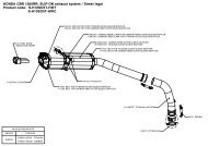
Yamaha YZF R6, Complete exhaust system / <strong>EVOLUTION</strong> LINE, model year: 2008-2010Product code: S-Y6RFT7TL-ZCS-Y6RFT7TL-ZTP-57 INNER SLEEVEP-F11 FLANGEH-Y6RT8 HEADER TUBEV-TUV081 NOISE REDUCTON INSERTM-Z02005T FULL TITANIUM MUFFLERM-Z02005C TITANIUM/CARBON OUTER SLEEVE MUFFLERP-HF161 FITTING PARTSP-GUV006 RUBBER SPACERP-LBSB1 LAMBDA CONNECTOR BOLTP-S1 SPRINGP-VST2AL STICKERC-Y6RT7 COLLECTOR SETP-MCCZ11 CARBON MUFFLER CLAMPFOR CARBON OUTER SLEEVE MUFFLERL-Y6E7TL LINK PIPEP-MCTZ11 CARBON MUFFLER CLAMPFOR TITANIUM OUTER SLEEVE MUFFLER
Yamaha YZF R6, Complete exhaust system / <strong>EVOLUTION</strong> KIT LINE, model year: 2008-2010Product code: S-Y6EFT7TL-ZCS-Y6EFT7TL-ZTP-57 INNER SLEEVEP-F11 FLANGEM-Z02105T FULL TITANIUM MUFFLERM-Z02105C TITANIUM/CARBON OUTER SLEEVE MUFFLERH-Y6RT8 HEADER TUBEP-GUV006 RUBBER SPACERP-HF161 FITTING PARTSP-LBSB1 LAMBDA CONNECTOR BOLTP-VST2AL STICKERC-Y6RT7 COLLECTOR SETP-MCCZ11 CARBON MUFFLER CLAMPFOR CARBON OUTER SLEEVE MUFFLERL-Y6E7TL LINK PIPEP-MCTZ11 CARBON MUFFLER CLAMPFOR TITANIUM OUTER SLEEVE MUFFLERP-S1 SPRING
Yamaha YZF R6, Complete exhaust system / <strong>EVOLUTION</strong> LINE tube set with Street legal SLIP on Mufflers, Model year: 2008 - 2009Product code: S-Y6RFT7TL-ZC/1S-Y6RFT7TL-ZT/1P-57 INNER SLEEVEP-F11 FLANGEV-TUV080 NOISE REDUCTION INSERTH-Y6RT7 HEADER TUBEM-HZ01905T TITANIUM MUFFLERM-HZ01905C TITANIUM MUFFLER WITH CARBON FIBRE OUTER SLEEVEP-MCCZ11 CARBON MUFFLER CLAMPFOR CARBON OUTER SLEEVE MUFFLERP-MCTZ11 CARBON MUFFLER CLAMPFOR TITANIUM OUTER SLEEVE MUFFLERP-S2 SPRINGP-LBSB1 LAMBDACONNECTOR BOLTP-VST2AL STICKERC-Y6RT6 COLLECTOR SETP-HF182 FITTING PARTSL-Y6R7TL/1 LINK PIPEP-S1 SPRING.
Yamaha YZF R6, Complete exhaust system / <strong>RACING</strong> LINE tube set with Street legal SLIP on Mufflers, Model year: 2010Product code: S-Y6R8-ASZ/1P-57 INNER SLEEVEP-F11 FLANGEV-TUV109 NOISE REDUCTION INSERTM-HAS1Z00202T TITANIUM MUFFLERH-Y6R8 HEADER TUBEP-HSY6R5 VALVE COVERP-HF471 FITTING KITP-GUV006 RUBBER SPACERP-R21 CLAMPP-HST6AL STICKERP-LBSB1 LAMBDACONNECTOR BOLTC-Y6R8 COLLECTOR SETL-Y6R8L LINK PIPEP-S1 SPRINGWARNING! THE SLIP ON HOMOLOGATION IS NOT VALID IN COMBINATION WITH <strong>RACING</strong> TUBE SET.