Validation of 2DOF Tracked Vehicle Model Due to Road Disturbance
Validation of 2DOF Tracked Vehicle Model Due to Road Disturbance
Validation of 2DOF Tracked Vehicle Model Due to Road Disturbance
- No tags were found...
Create successful ePaper yourself
Turn your PDF publications into a flip-book with our unique Google optimized e-Paper software.
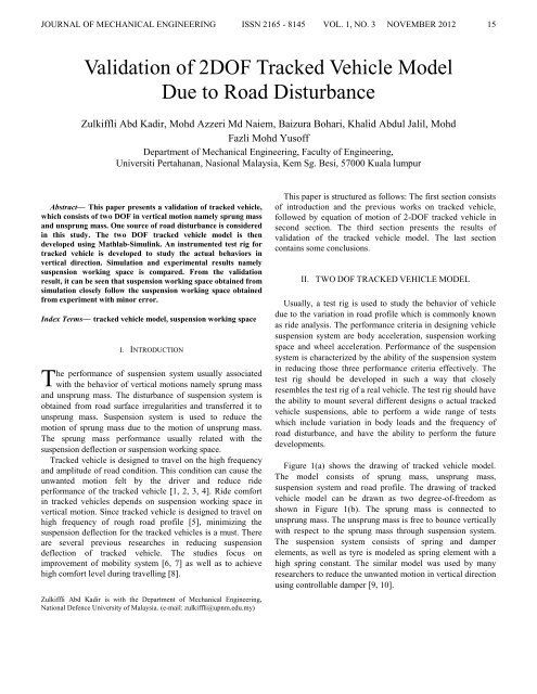
JOURNAL OF MECHANICAL ENGINEERING ISSN 2165 - 8145 VOL. 1, NO. 3 NOVEMBER 2012 15<strong>Validation</strong> <strong>of</strong> <strong>2DOF</strong> <strong>Tracked</strong> <strong>Vehicle</strong> <strong>Model</strong><strong>Due</strong> <strong>to</strong> <strong>Road</strong> <strong>Disturbance</strong>Zulkiffli Abd Kadir, Mohd Azzeri Md Naiem, Baizura Bohari, Khalid Abdul Jalil, MohdFazli Mohd Yus<strong>of</strong>fDepartment <strong>of</strong> Mechanical Engineering, Faculty <strong>of</strong> Engineering,Universiti Pertahanan, Nasional Malaysia, Kem Sg. Besi, 57000 Kuala lumpurAbstract— This paper presents a validation <strong>of</strong> tracked vehicle,which consists <strong>of</strong> two DOF in vertical motion namely sprung massand unsprung mass. One source <strong>of</strong> road disturbance is consideredin this study. The two DOF tracked vehicle model is thendeveloped using Mathlab-Simulink. An instrumented test rig fortracked vehicle is developed <strong>to</strong> study the actual behaviors invertical direction. Simulation and experimental results namelysuspension working space is compared. From the validationresult, it can be seen that suspension working space obtained fromsimulation closely follow the suspension working space obtainedfrom experiment with minor error.Index Terms— tracked vehicle model, suspension working spaceTI. INTRODUCTIONhe performance <strong>of</strong> suspension system usually associatedwith the behavior <strong>of</strong> vertical motions namely sprung massand unsprung mass. The disturbance <strong>of</strong> suspension system isobtained from road surface irregularities and transferred it <strong>to</strong>unsprung mass. Suspension system is used <strong>to</strong> reduce themotion <strong>of</strong> sprung mass due <strong>to</strong> the motion <strong>of</strong> unsprung mass.The sprung mass performance usually related with thesuspension deflection or suspension working space.<strong>Tracked</strong> vehicle is designed <strong>to</strong> travel on the high frequencyand amplitude <strong>of</strong> road condition. This condition can cause theunwanted motion felt by the driver and reduce rideperformance <strong>of</strong> the tracked vehicle [1, 2, 3, 4]. Ride comfortin tracked vehicles depends on suspension working space invertical motion. Since tracked vehicle is designed <strong>to</strong> travel onhigh frequency <strong>of</strong> rough road pr<strong>of</strong>ile [5], minimizing thesuspension deflection for the tracked vehicles is a must. Thereare several previous researches in reducing suspensiondeflection <strong>of</strong> tracked vehicle. The studies focus onimprovement <strong>of</strong> mobility system [6, 7] as well as <strong>to</strong> achievehigh comfort level during travelling [8].Zulkiffli Abd Kadir is with the Department <strong>of</strong> Mechanical Engineering,National Defence University <strong>of</strong> Malaysia. (e-mail: zulkiffli@upnm.edu.my)This paper is structured as follows: The first section consists<strong>of</strong> introduction and the previous works on tracked vehicle,followed by equation <strong>of</strong> motion <strong>of</strong> 2-DOF tracked vehicle insecond section. The third section presents the results <strong>of</strong>validation <strong>of</strong> the tracked vehicle model. The last sectioncontains some conclusions.II. TWO DOF TRACKED VEHICLE MODELUsually, a test rig is used <strong>to</strong> study the behavior <strong>of</strong> vehicledue <strong>to</strong> the variation in road pr<strong>of</strong>ile which is commonly knownas ride analysis. The performance criteria in designing vehiclesuspension system are body acceleration, suspension workingspace and wheel acceleration. Performance <strong>of</strong> the suspensionsystem is characterized by the ability <strong>of</strong> the suspension systemin reducing those three performance criteria effectively. Thetest rig should be developed in such a way that closelyresembles the test rig <strong>of</strong> a real vehicle. The test rig should havethe ability <strong>to</strong> mount several different designs o actual trackedvehicle suspensions, able <strong>to</strong> perform a wide range <strong>of</strong> testswhich include variation in body loads and the frequency <strong>of</strong>road disturbance, and have the ability <strong>to</strong> perform the futuredevelopments.Figure 1(a) shows the drawing <strong>of</strong> tracked vehicle model.The model consists <strong>of</strong> sprung mass, unsprung mass,suspension system and road pr<strong>of</strong>ile. The drawing <strong>of</strong> trackedvehicle model can be drawn as two degree-<strong>of</strong>-freedom asshown in Figure 1(b). The sprung mass is connected <strong>to</strong>unsprung mass. The unsprung mass is free <strong>to</strong> bounce verticallywith respect <strong>to</strong> the sprung mass through suspension system.The suspension system consists <strong>of</strong> spring and damperelements, as well as tyre is modeled as spring element with ahigh spring constant. The similar model was used by manyresearchers <strong>to</strong> reduce the unwanted motion in vertical directionusing controllable damper [9, 10].
JOURNAL OF MECHANICAL ENGINEERING ISSN 2165 - 8145 VOL. 1, NO. 3 NOVEMBER 2012 16Equations <strong>of</strong> motion in (1) and (2) for both sprung andunsprung masses can be rewritten due <strong>to</strong> the effect <strong>of</strong> springelement, damper element and road input:K ( Z Z ) C ( Z Z) m Z(3)susdusK ( Z Z ) K ( Z Z ) C( Z Z) m Z(4)trusussdsusuuwhere,K s = suspension spring stiffnessC d = suspension dampingZu = unsprung mass displacement(a)Zs = sprung mass displacementZr= road inputZ u= unsprung mass velocityZ s= sprung mass velocity(b)Figure 1: <strong>Tracked</strong> <strong>Vehicle</strong> <strong>Model</strong>The tracked vehicle model is then developed in Matlab-Simulink based on mathematical equation that has beenderived and discussed. The relationship <strong>of</strong> unsprung mass,sprung mass and road pr<strong>of</strong>ile is illustrated in Figure 2. Input <strong>of</strong>the model is road pr<strong>of</strong>ile with maximum amplitude <strong>of</strong> 0.06mand frequency <strong>of</strong> 14.3Hz as presented in Figure 3. Theparameters <strong>of</strong> the 2-DOF tracked vehicle are shown in Table 1and some <strong>of</strong> the values <strong>of</strong> parameters are assumed. Thebehavior <strong>of</strong> suspension system namely suspension workingspace is compared with the experimental result.From the Figure 1(b), the force on sprung mass is written as:Fs F m Z(1)dsswhere,F s = spring forceF d = damper forcem s = sprung massZ s = sprung mass accelerationThe force balance on unsprung mass can be written as:Ft F F m Z(2)sduuwhere,F t = tyre forcem u = unsprung massZ u= unsprung mass accelerationFigure 2: <strong>Tracked</strong> vehicle model in Matlab-Simulink
JOURNAL OF MECHANICAL ENGINEERING ISSN 2165 - 8145 VOL. 1, NO. 3 NOVEMBER 2012 17The dynamic response characteristics <strong>of</strong> a test rig that includesuspension working space and road pr<strong>of</strong>ile can be verifiedusing actual data through road disturbance procedure. Inexperimental work, the data <strong>of</strong> suspension working space isfiltered using low pass filter while the simulation is completedfor a period <strong>of</strong> 3.5 seconds. The validation result can beobtained in Figure 5. It can be seen that the magnitude <strong>of</strong> bothresults are similar with maximum magnitude <strong>of</strong> 0.015m. Thedifference value in magnitude for both results might be due <strong>to</strong>the effect <strong>of</strong> DC mo<strong>to</strong>r as road input in experimental test. Itcan be said that the model is valid in representing actual smallscaledsystem <strong>of</strong> tracked vehicle.Figure 3: <strong>Road</strong> InputIII. VALIDATION RESULTThe measurement computing is installed in<strong>to</strong> trackedvehicle test rig <strong>to</strong> obtain the experimental data <strong>to</strong> evaluate thesuspension performance in terms <strong>of</strong> suspension working spaceand acceleration <strong>of</strong> road input. The measurement computingconnected with several types <strong>of</strong> sensors namely accelerometersensor <strong>to</strong> measure the road pr<strong>of</strong>ile and LVDT <strong>to</strong> measure thesuspension deflection. DaisyLab s<strong>of</strong>tware is used as the realtime data collecting and show the result as a graph. Theinstallation <strong>of</strong> the measurement computing and transducers <strong>to</strong>the tracked vehicle test rig can be obtained in Figure 4.Figure 5: <strong>Validation</strong> resultTABLE ITHE NUMERICAL VALUES OF THE TRACKED VEHICLE MODELSymbol Quantity ValueKs Spring stiffness 37500Cd Damper stiffness 1000ms Sprung mass 10mu Unsprung mass 5Kt Tyre stiffness 30000There are several potential applications <strong>of</strong> the tracked vehicletest rig that has been developed such as able <strong>to</strong> investigate thetracked vehicle response due <strong>to</strong> road disturbance as well asability <strong>to</strong> study the damping behaviors <strong>of</strong> suspension system.For the future research, the test rig can be used <strong>to</strong> perform astudy on the application <strong>of</strong> a controllable damper in reducingthe vibration and unwanted motion in vertical.Figure 4: Instrumented test rigIV. CONCLUSIONSA 2-DOF tracked vehicle model which consists <strong>of</strong> sprungand unsprung masses has been developed in Mathlab-Simulink. An instrumented test rig has been developed <strong>to</strong>verify the tracked vehicle model with the two types <strong>of</strong>transducers and measurement computing system. One road
JOURNAL OF MECHANICAL ENGINEERING ISSN 2165 - 8145 VOL. 1, NO. 3 NOVEMBER 2012 18disturbance test has been considered as the input and resultcollected from the test was set as the basic target <strong>of</strong> the modelverification. The result <strong>of</strong> model validation shows that thebehavior <strong>of</strong> suspension working space <strong>of</strong> both simulation andexperimental results are similar in terms <strong>of</strong> the maximummagnitude.REFERENCES[1] Ming-ming, D. and Liang, G., “Simulation Of Nonlinear<strong>Tracked</strong> <strong>Vehicle</strong> Suspension With ADAMS”, Journal <strong>of</strong>Beijing Institute <strong>of</strong> Technology, ISSN:1001-0645.0.2005-08-003, 2005.[2] Sankar, S., Dhir, A. and Shankhla, V., “Simulation AndField Testing Of <strong>Tracked</strong> <strong>Vehicle</strong> Suspension Dynamics”,Proc. ASME Winter Annual Meeting, Atlanta, Georgia,U.S.A, pp. 423–436, 1–6 December , 1991.[3] Rakheja, S., Afonso, M. F. R. and Sankar, S., “DynamicAnalysis Of <strong>Tracked</strong> <strong>Vehicle</strong>s With Trailing ArmSuspension And Assessment Of Ride Vibrations”,International Journal <strong>of</strong> <strong>Vehicle</strong> Design, Vol.13, No.1,1992.[4] Yamakawa, J. and Watanabe, K., “A Spatial MotionAnalysis <strong>Model</strong> Of <strong>Tracked</strong> <strong>Vehicle</strong>s With Torsion BarType Suspension”, Journal <strong>of</strong> Terramechanics, Vol. 41,Issues 2–3, pp. 113–126, 2004.[5] Ryu, H. S., Bae, D. S., Choi, J. H. and Shabanain, A. A.,“A Compliant Track Link <strong>Model</strong> For High-Speed, High-Mobility <strong>Tracked</strong> <strong>Vehicle</strong>s”, International Journal forNumerical Methods in Engineering, Vol. 48, Issue 10, pp1481–1502, 2000.[6] Ferretti, G. and Girelli, R., “<strong>Model</strong>ling And Simulation OfAn Agricultural <strong>Tracked</strong> <strong>Vehicle</strong>”, Journal <strong>of</strong>Terramechanics, Vol. 36, Issue 3, pp. 139–158, 1999.[7] Bodin, A., “Development Of A <strong>Tracked</strong> <strong>Vehicle</strong> To StudyThe Influence Of <strong>Vehicle</strong> Parameters On TractivePerformance In S<strong>of</strong>t Terrain”, Journal <strong>of</strong> Terramechanics,Vol. 36, Issue 3, pp 167–181, 1999.[8] Dhir, A. and Sankar, S., “Analytical Track <strong>Model</strong>s ForRide Dynamic Simulation Of <strong>Tracked</strong> <strong>Vehicle</strong>s”, Journal<strong>of</strong> Terramechanics, Vol. 31, Issue 2, pp 107–138, 1994.[9] Prabakar, R. S., Sujatha, C. and Narayanan, S., “StationaryResponse Of A Quarter Car <strong>Vehicle</strong> <strong>Model</strong> WithMagne<strong>to</strong>rheological Damper”, Int. J. <strong>of</strong> <strong>Vehicle</strong> Systems<strong>Model</strong>ling and Testing,Vol. 3, No.4, pp. 251 – 270, 2008.[10] Ubaidillah, Hudha, K. and Jamaluddin, H., “SimulationAnd Experimental Evaluation On A Skyhook Policy-BasedFuzzy Logic Control For Semi-Active Suspension System”,Int. J. <strong>of</strong> Structural Engineering, Vol. 2, No.3, pp. 243 –272, 2011.Zulkiffli Abd Kadir received his BEng and MSc in theDepartment <strong>of</strong> Au<strong>to</strong>motive Engineering, Universiti TeknikalMalaysia Melaka. He is currently attached with the NationalDefence University <strong>of</strong> Malaysia. His research interests includetyre modeling, evaluation <strong>of</strong> vehicle dynamics and control.Mohd Azzeri Md Naiem received his both BEng inMechanical Engineering and MEng in Mechanical Engineering(Marine Technology) from Malaysia University <strong>of</strong> Technology(UTM). He is currently attached with the National DefenceUniversity <strong>of</strong> Malaysia. His research interests include marinetechnology system and ship maintenance system.Baizura Bohari received her BEng (Hons) in AerospaceEngineering from Universiti Putra Malaysia and completed herMSc <strong>of</strong> Aerospace Technology at University <strong>of</strong> Sussex, UK.Her research interests include CFD modelling on aircraftengine, aerodynamics analysis <strong>of</strong> a wind turbine andevaluation <strong>of</strong> impact dynamics and kinetic energy projectiledesign.Khalid Abd Jalil was born on 1963 at Johor, Malaysia. Lt ColIr Khalid Abd Jalil received his BSc in MechanicalEngineering from Han Yang University, Seoul Korea andcompleted his Master in Airworthiness and Aircraft Safetyfrom ENCISA/ENCA, Toulouse, France. He served in the AirForce since 1989 as an engineer and was seconded <strong>to</strong> NationalDefence University, Malaysia (UPNM) as academics since2004. He has more than 15 years experience in themaintenance <strong>of</strong> military aircraft and as a lecturer; he is alsoactively involved with research work. He currently works as anAssociate Pr<strong>of</strong>essor in Faculty <strong>of</strong> Engineering, and held theposition as Deputy Dean, Faculty <strong>of</strong> Engineering. He is apr<strong>of</strong>essional engineer registered with the Board <strong>of</strong> EngineersMalaysia and he research interests is on small arms ballisticimpact on s<strong>of</strong>t body armor.Mohd Fazli Mohd Yus<strong>of</strong>f received his BEng from UIAM inMechatronic Engineering. Then he obtained his MSc inEngineering from Australia National University (ANU). He iscurrently attached with the National Defence University <strong>of</strong>Malaysia. His research interest is in intelligent control systemand evaluation <strong>of</strong> dynamic system.


