Wideband Microstrip Patch Antenna at 7 GHz - Sonnet Software
Wideband Microstrip Patch Antenna at 7 GHz - Sonnet Software
Wideband Microstrip Patch Antenna at 7 GHz - Sonnet Software
Create successful ePaper yourself
Turn your PDF publications into a flip-book with our unique Google optimized e-Paper software.
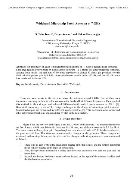
27th Annual Review of Progress in Applied Comput<strong>at</strong>ional ElectromagneticsMarch 27-31, 2011 - Williamsburg, Virginia ©2011 ACES<strong>Wideband</strong> <strong>Microstrip</strong> <strong>P<strong>at</strong>ch</strong> <strong>Antenna</strong> <strong>at</strong> 7 <strong>GHz</strong>Ş. Taha İmeci 1 , Derya Arıcan 2 and Hakan Hızarcıoğlu 21 Department of Electrical and Electronics EngineeringKTO Kar<strong>at</strong>ay University, Konya, TURKEYtaha.imeci@kar<strong>at</strong>ay.edu.tr2Department of Electronics and Communic<strong>at</strong>ion EngineeringHaliç University, İstanbul, TURKEYaricanderya@hotmail.com, hakanhizarcioglu@yahoo.com.trAbstract: : In this study, an edge-fed microstrip p<strong>at</strong>ch antenna <strong>at</strong> 7.1 <strong>GHz</strong> is designed and simul<strong>at</strong>ed.Simul<strong>at</strong>ed results are presented by using <strong>Sonnet</strong> software [1], a planar 3D electromagnetic simul<strong>at</strong>or.Among those results, the real part of the input impedance is almost 50 ohms, phi-polarized electricfield radi<strong>at</strong>ion p<strong>at</strong>tern gain is 4.5 dB, cross-polariz<strong>at</strong>ion level is under –20 dB, and the –10 dB returnloss bandwidth is almost 10%.Keywords: <strong>Microstrip</strong>, <strong>P<strong>at</strong>ch</strong>, <strong>Antenna</strong>, Bandwidth, <strong>Wideband</strong>1. IntroductionThere are some works in the liter<strong>at</strong>ure about the antennas around 7 <strong>GHz</strong>. One of them usesimpedance m<strong>at</strong>ching method in order to increase the bandwidth <strong>at</strong> different frequencies. They appliedthis method to their design, and achieved 20%-bandwidth stacked p<strong>at</strong>ch antenna <strong>at</strong> 7<strong>GHz</strong> [2].Bandwidth increasing is one of the design challenges in the design of microstrip p<strong>at</strong>ch antennas.Several techniques are formulized for different input geometries [3]. This work uses some similar andother different approaches as explained step by step in the next section.2. Design procedureFigure 1 has the top view and Figure 2 has the 3D view of the antenna. The antenna dimensionsare 30.15 mm x 43.48 mm. Dielectric thickness is 2.54 mm., and dielectric constant is 3.9 for FR–4.The work started with very low gain. Even though the return loss of under –20 db levels are achieved,the gain was still low. This situ<strong>at</strong>ion caused to make changes on the geometry. Those changes areexplained in three steps below, and the affects of the changes in the design parameters are mentionedin Table 1.1. There was no gain without the indent<strong>at</strong>ion loc<strong>at</strong>ed <strong>at</strong> the top-center, and the bottom horizontalmetal radi<strong>at</strong>or loc<strong>at</strong>ed <strong>at</strong> the input of the antenna.2. First, the top-center indent<strong>at</strong>ion is added and there was an increase on both the gain and thereturn loss.3. Second, the bottom horizontal metal radi<strong>at</strong>or loc<strong>at</strong>ed <strong>at</strong> the input of the antenna is added andthe final results are achieved.261
27th Annual Review of Progress in Applied Comput<strong>at</strong>ional ElectromagneticsMarch 27-31, 2011 - Williamsburg, Virginia ©2011 ACESTable 1:Parameter value changes with design stepsParameters 1. step 2. step 3. stepResonance frequency 7.1 <strong>GHz</strong> 7.1 <strong>GHz</strong> 7.03 <strong>GHz</strong>S11 -15.74 dB -21.3878 dB -17.02 dBBandwidth (freq.)Bandwidth (%)400 MHz5.63 %600 MHz8.45 %550 MHz9.23 %Gain 1.337 dB 3.37 dB 3.76 dBFig. 1. Top view of the antenna.Fig. 2. 3D view of the antenna.262
27th Annual Review of Progress in Applied Comput<strong>at</strong>ional ElectromagneticsMarch 27-31, 2011 - Williamsburg, Virginia ©2011 ACES3. Simul<strong>at</strong>ion ResultsFigure 3 has the return loss of the antenna <strong>at</strong> 7.03 <strong>GHz</strong>, when air layer thickness is 20 mm.BW = 10 %Fig. 3. Return loss of the p<strong>at</strong>ch antenna.The real part of the input impedance is 65 Ω, and the imaginary part of the input impedance is3.16 Ω. When we make the air layer thickness 100 mm. for the step 3, maximum gain of 4.49 dB ismaintained with a fraction of a frequency shift, but the bandwidth is decreased. This p<strong>at</strong>tern is seen onFigure 4. The real part of the input impedance is 50.3 Ω, and the imaginary part of the inputimpedance is 7.33 Ω. Those changes are explained in Table 2.Table 2:Parameter value changes with air layer thickness of 100 mmResonance frequency 7.03 <strong>GHz</strong> 7.1 <strong>GHz</strong>S11 -22.82 dB -17.02 dBBandwidth (%) 2.27 % 5.23 %Gain 3.03 dB 4.49 dBThe phi-polarized electric field radi<strong>at</strong>ion p<strong>at</strong>tern is illustr<strong>at</strong>ed on Figure 4. As it is seen on thefigure th<strong>at</strong>, the cross-pol. level (E-theta) is –20 dB, and the p<strong>at</strong>tern is symmetric.263
27th Annual Review of Progress in Applied Comput<strong>at</strong>ional ElectromagneticsMarch 27-31, 2011 - Williamsburg, Virginia ©2011 ACESFig. 4. Far field radi<strong>at</strong>ion p<strong>at</strong>tern of the antenna <strong>at</strong> 7.1 <strong>GHz</strong>.The current on the antenna can be seen on Figure 5. As the affect on the gain is explained insection 2, the current is very crowded <strong>at</strong> the bottom horizontal metal radi<strong>at</strong>or loc<strong>at</strong>ed <strong>at</strong> the input of theantenna.Fig. 5. Current distribution on the antenna <strong>at</strong> 7.1 <strong>GHz</strong>.Finally, in order to get rid of the long edge-feeding line, probe-feeding is applied. Figure 6 hasthe top view, and Figure 7 has the 3D view of the probe-feeded antenna.264
27th Annual Review of Progress in Applied Comput<strong>at</strong>ional ElectromagneticsMarch 27-31, 2011 - Williamsburg, Virginia ©2011 ACESFig.6. Top view of the probe-fed antenna.Fig.7. 3D view of the probe-fed antenna.Figure 8 has the return loss of the antenna <strong>at</strong> 6.92 <strong>GHz</strong> and 6.99 <strong>GHz</strong>. Figure show th<strong>at</strong>,magnitude odf the return loss and the center frequency did not change much as compared to edgefeeding,but bandwidth decreased to 4%.BW =4 %Fig. 8. Return loss of the p<strong>at</strong>ch antenna.Real part of the input impedance is 57.04 Ω, and the imaginary part of the input impedance is–7.1 Ω and maximum gain is 6.83 dB for the 6.92<strong>GHz</strong>. Radi<strong>at</strong>ion p<strong>at</strong>tern is on Figure 9. As it is seenon the figure th<strong>at</strong>, the cross-pol. level (E-theta) is increased to approxim<strong>at</strong>ely –10 dB, <strong>at</strong> the endfireradi<strong>at</strong>ion directions.265
27th Annual Review of Progress in Applied Comput<strong>at</strong>ional ElectromagneticsMarch 27-31, 2011 - Williamsburg, Virginia ©2011 ACESFig. 9. Far field radi<strong>at</strong>ion p<strong>at</strong>tern of the antenna <strong>at</strong> 6.92 <strong>GHz</strong>.4. ConclusionsA microstrip p<strong>at</strong>ch antenna <strong>at</strong> a resonance frequency of 7.03 <strong>GHz</strong>, with 50.3 Ω input impedance,10% of bandwidth, and 4.5 dB of phi-polarized gain is achieved. The gain is increased to 6.83 dBwhen probe-feeding is applied. Design is modified by changing the geometry in order to reach thedesign specific<strong>at</strong>ions. The main design challenge was having low gain in spite of a few resonances oflow return losses <strong>at</strong> different frequencies. For example, there is a resonance <strong>at</strong> 17 <strong>GHz</strong> but the gain is<strong>at</strong> minus digit levels. Further studies might be conducted to improve this. The goal is to have amultiple resonance antenna with wider bandwidths.References1 <strong>Sonnet</strong> <strong>Software</strong>, version 12.56, www.sonnetsoftware.com, 2009.2 L. Le Coq, O. Roncière, R. Sauleau, K. Mahdjoubi, “A Stepwise and Effective Procedure forImpedance M<strong>at</strong>ching of Slot-Fed Planar <strong>Antenna</strong>s.Applic<strong>at</strong>ion to the Design of Wide Band Printed<strong>Antenna</strong>s and Reconfigurable Ebg Reson<strong>at</strong>or” , Proceedings of The European Conference on<strong>Antenna</strong>s and Propag<strong>at</strong>ion: EuCAP 2006, Pages 1-5.3 E. Arvas, Planar Microwave <strong>Antenna</strong>s Course Notes, Syracuse University, Spring 2003.266


