Design of a V-band Phase Shifter Using SP4T RF ... - Sonnet Software
Design of a V-band Phase Shifter Using SP4T RF ... - Sonnet Software
Design of a V-band Phase Shifter Using SP4T RF ... - Sonnet Software
- No tags were found...

You also want an ePaper? Increase the reach of your titles
YUMPU automatically turns print PDFs into web optimized ePapers that Google loves.
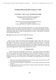
27th Annual Review <strong>of</strong> Progress in Applied Computational ElectromagneticsMarch 27-31, 2011 - Williamsburg, Virginia ©2011 ACES<strong>Design</strong> <strong>of</strong> a V-<strong>band</strong> <strong>Phase</strong> <strong>Shifter</strong> <strong>Using</strong> <strong>SP4T</strong> <strong>RF</strong>-MEMS Switches with<strong>Sonnet</strong>1 Songbin Gong and 2 N Scott Barker1 Department <strong>of</strong> Electrical and Systems EngineeringUniversity <strong>of</strong> Pennsylvania, Philadelphia, PA 19104, USASongbin@seas.upenn.edu2 Charles L. Brown Department <strong>of</strong> Electrical and Computer EngineeringUniversity <strong>of</strong> Virginia, Charlottesville, VA 22903, USABarker@virginia.eduAbstract: This paper presents the design <strong>of</strong> a V-<strong>band</strong> switched-line phase shifter using <strong>SP4T</strong> <strong>RF</strong>-MEMSswitches. <strong>Sonnet</strong> simulations are used to achieve accurate circuit models <strong>of</strong> both the <strong>RF</strong>-MEMS switchesas well as CPW bends within the phase shifter. The V-<strong>band</strong> phase shifter utilizes two <strong>SP4T</strong> <strong>RF</strong>-MEMSswitches to perform the delay line switching. The <strong>RF</strong> performance <strong>of</strong> the <strong>SP4T</strong> MEMS switch isoptimized to address the challenge <strong>of</strong> developing high performance, broad<strong>band</strong> switches for emerging60 GHz wireless applications. Full-wave <strong>Sonnet</strong> simulations are used to optimize the <strong>RF</strong>-MEMS switchtopology to achieve low return-loss performance. The <strong>SP4T</strong> SONNET model is then used in the circuitsimulation to analyze the performance <strong>of</strong> the <strong>RF</strong>-MEMS integrated V-<strong>band</strong> phase shifter. Theexperimental result shows less than 1° phase error at 60 GHz in comparison to the simulation results.Keywords: <strong>RF</strong> MEMS, <strong>SP4T</strong>, SONNET, cantilever switches.1. IntroductionWith the maturing <strong>of</strong> radio frequency microelectromechanical systems (<strong>RF</strong>-MEMS) technologyin the last ten years, there have emerged numerous applications using <strong>RF</strong>-MEMS technology atmillimeter-wave frequencies including radar systems for defense applications, satellite communicationsystems, and terrestrial communication systems [1]. In particular, the 60 GHz <strong>band</strong> has attracted a greatamount <strong>of</strong> research interest due to potential applications for indoor broad<strong>band</strong> wireless communications.However, 60 GHz applications face multiple challenges including high path-loss (10-15 dB/km) due toatmospheric oxygen and multipath effects due to the cluttered indoor environment. Adaptivebeamformers are one <strong>of</strong> the promising solutions needed to effectively exploit this frequency <strong>band</strong> bygenerating the required radiation patterns for operating in such a complex environment.Single-pole 4-throw (<strong>SP4T</strong>) <strong>RF</strong>-MEMS switches are important enabling components for low-lossbroad<strong>band</strong> implementations <strong>of</strong> true-time delay phase shifters required to implement these beamformers.Most single-pole multi-throw (SPMT) switches developed thus far are built by surrounding the input withmultiple SPST switches controlling the corresponding signal path. Despite the outstanding performance<strong>of</strong> the SPST switch on which they are based, these previously developed <strong>SP4T</strong> switches are all limited to418
27th Annual Review <strong>of</strong> Progress in Applied Computational ElectromagneticsMarch 27-31, 2011 - Williamsburg, Virginia ©2011 ACESbelow 50 GHz due to their relatively long spokes. This work presents the design <strong>of</strong> an <strong>SP4T</strong> MEMSswitch using the cantilever <strong>RF</strong>-MEMS switch developed in [2] and a V-<strong>band</strong> 2-bit phase shifter with such<strong>SP4T</strong> switches integrated. The cantilever switch has dimensions <strong>of</strong> 75 µm by 30 µm. The switch isdesigned to be integrated into a 7/50/7 µm CPW line on a 500-µm thick quartz substrate.2. <strong>Design</strong> <strong>of</strong> the <strong>SP4T</strong> <strong>RF</strong>-MEMS SwitchesMost single-pole multiple-throw (SPMT) switches developed thus far are built by surrounding theinput with multiple SPST switches controlling the corresponding signal path. The performance <strong>of</strong> theSPMT switch greatly depends on the performance <strong>of</strong> the SPST and the proximity with which the SPSTswitches can be arrange in relation to the central hub (see Fig.1). The topology <strong>of</strong> the central hub and thespokes connecting the switch and center hub generally introduce impedance mismatch and thus degradethe return loss performance <strong>of</strong> the SPMT switches. In order to minimize this mismatch in our design, wehave used cantilever switches placed in series with the CPW transmission line. These series switches havean upstate capacitance <strong>of</strong> 2 fF resulting in an isolation <strong>of</strong> better than 15 dB up to 75 GHz. With an appliedactuation voltage <strong>of</strong> 75 V, the insertion loss is less than 0.2 dB up to 20 GHz and less than 0.4 dB up to50 GHz.As shown in Fig. 2, a <strong>Sonnet</strong> model is constructed to enhance the understanding <strong>of</strong> the return lossperformance <strong>of</strong> the <strong>SP4T</strong> switch shown in Fig. 1 and used in this work. In the downstate position, theactuated cantilever is represented by a metal strip suspended 1.25 µm above the circuit layer with viaholes on both ends to connect the gap in the circuit. In the up-state position, the metal strip is suspended1.25 µm over the central hub with a 5 µm by 30 µm overlap. Air bridges are also used in this design toequalize the CPW ground-planes. Air bridges are represented by a metal strip with via holes on both endsconnecting the air-bridge to the CPW metal level. This type <strong>of</strong> design provides greater simplicity in thefabrication <strong>of</strong> the <strong>SP4T</strong> switches.A general circuit representation <strong>of</strong> the <strong>SP4T</strong> switch that can be used for design optimization isshown in Fig. 3. In this generalized circuit, Z s is the normalized characteristic impedance <strong>of</strong> theconnecting spoke with an electrical length <strong>of</strong> θ, X C and X L are the normalized reactances introduced by theupstate capacitance and parasitic inductance <strong>of</strong> the switch, and R C is the downstate contact resistance <strong>of</strong>the switch. X C , X L , and R C are parameters determined by the SPST switch on which the SPMT is based.Fig.1. The designed layout <strong>of</strong> <strong>SP4T</strong> <strong>RF</strong> MEMSswitches.Fig. 2. The 3D SONNET representation <strong>of</strong>the <strong>SP4T</strong> <strong>RF</strong>-MEMS switch.419
27th Annual Review <strong>of</strong> Progress in Applied Computational ElectromagneticsMarch 27-31, 2011 - Williamsburg, Virginia ©2011 ACES(a)(b)Fig. 5 The phase shifter delayline topology.Fig. 6. Layout <strong>of</strong> the (a) 90° and (b) 36° bend.3. V-<strong>band</strong> <strong>Phase</strong> <strong>Shifter</strong>A V-<strong>band</strong> 2-bit phase shifter is designed with three delay lines providing 90°/180°/270° phase shift inrelation to the reference line at 60 GHz as shown in Fig. 5. These four delay lines are connected to theinput and output using two <strong>SP4T</strong> <strong>RF</strong>-MEMS switches. While in operation, each phase delay path ischosen by actuating the corresponding two throws. In order to achieve a compact design with minimumphase error, the reference path is chosen to be 556 µm (electrical length: 43°@ 60 GHz). This allows four90° CPW bends to fit in-between the two <strong>SP4T</strong> switches to form the 90° delay path with littletransmission distortion caused by intra-coupling in the meandering lines. Two 36° CPW bends areconfigured to connect the <strong>SP4T</strong> switches to the reference and 90° delay lines. The 90° CPW and 36°bends in this work use the standard design described in [2]. Air-bridges are used in CPW based circuits tosuppress the parasitic slot-line mode. The layout <strong>of</strong> the 90° and 36° CPW bend are shown in Fig. 6. TheS-parameter performance <strong>of</strong> the 90° and 36° CPW bends are simulated using <strong>Sonnet</strong> and is plotted alongwith the measurement results in Figs. 7 and 8. Although the measured insertion loss and return loss(a)(b)Fig. 7. Measured and Simulated (a) S-parameter performance and (b) phase delay <strong>of</strong> the 90° CPWbend.421
27th Annual Review <strong>of</strong> Progress in Applied Computational ElectromagneticsMarch 27-31, 2011 - Williamsburg, Virginia ©2011 ACES(a)Fig. 8. Measured and Simulated (a) S-parameter performance and (b) phase delay <strong>of</strong> the 36°CPW bend.performance are worse than the simulation results, both bends demonstrate a return loss better than 17 dBand insertion loss less than 0.3 dB in the <strong>band</strong> <strong>of</strong> interest. More importantly, the phase delay <strong>of</strong> bothbends matches the measured results to within
27th Annual Review <strong>of</strong> Progress in Applied Computational ElectromagneticsMarch 27-31, 2011 - Williamsburg, Virginia ©2011 ACES4. ConclusionsA V-<strong>band</strong> switched-line phase shifter using <strong>SP4T</strong> <strong>RF</strong>-MEMS switches is designed with <strong>Sonnet</strong>. Thesimulation predicts outstanding return loss performance for the <strong>SP4T</strong> switches and V-<strong>band</strong> phase shifterwith better than 13 dB from 55 to 65 GHz. Through the judicious use <strong>of</strong> both <strong>Sonnet</strong> and circuitsimulations, an accurate simulation <strong>of</strong> the phase shifter circuit is obtained with the resulting measuredphase error less than 1° at 60 GHz across all four phase states. Full-wave simulations using <strong>Sonnet</strong> areshown to be <strong>of</strong> great importance to the design and optimization <strong>of</strong> millimeter-wave components. Theyinclude the more pronounced coupling effect in millimeter-wave systems due to their generally compactfootprint. Full understanding <strong>of</strong> the designed circuit and switching component performance thus can beachieved, bridging the gap between simulations and measurements to better serve performance budgetingand integration on a system level.References1 G. Rebeiz and J. Muldavin, “<strong>RF</strong> MEMS switches and switch circutis,” Microwave Magazine, IEEE,vol. 2, no. 4, pp. 59-71, 2001.2 R. N. Simons, Coplanar Waveguide circuits, Components, and Systems, Wiley, 2001.3 S. Gong, H. Shen, and N. S. Barker, "A cryogenic broad<strong>band</strong> DC contact <strong>RF</strong> MEMS switch," in 2009IEEE MTT-S Int. Microwave Symp. Dig., vol. 1, 2009, pp. 227-230.4 S. Gong, H. Shen, and N. S. Barker, "A 60 GHz 2-bit Switched-line <strong>Phase</strong> <strong>Shifter</strong> using <strong>SP4T</strong> <strong>RF</strong>-MEMS Switches" Microwave Theory and Techniques, IEEE Transactions on, 2010 (In Press).423