Design of a V-band Phase Shifter Using SP4T RF ... - Sonnet Software
Design of a V-band Phase Shifter Using SP4T RF ... - Sonnet Software
Design of a V-band Phase Shifter Using SP4T RF ... - Sonnet Software
- No tags were found...

You also want an ePaper? Increase the reach of your titles
YUMPU automatically turns print PDFs into web optimized ePapers that Google loves.
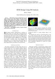
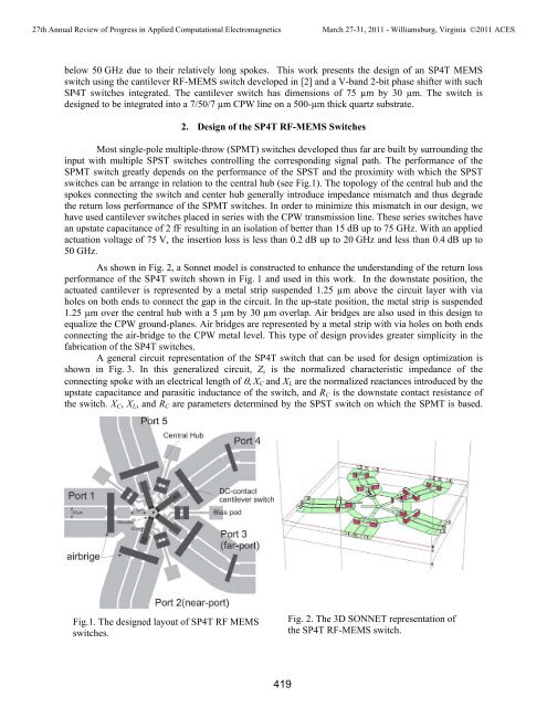
27th Annual Review <strong>of</strong> Progress in Applied Computational ElectromagneticsMarch 27-31, 2011 - Williamsburg, Virginia ©2011 ACESbelow 50 GHz due to their relatively long spokes. This work presents the design <strong>of</strong> an <strong>SP4T</strong> MEMSswitch using the cantilever <strong>RF</strong>-MEMS switch developed in [2] and a V-<strong>band</strong> 2-bit phase shifter with such<strong>SP4T</strong> switches integrated. The cantilever switch has dimensions <strong>of</strong> 75 µm by 30 µm. The switch isdesigned to be integrated into a 7/50/7 µm CPW line on a 500-µm thick quartz substrate.2. <strong>Design</strong> <strong>of</strong> the <strong>SP4T</strong> <strong>RF</strong>-MEMS SwitchesMost single-pole multiple-throw (SPMT) switches developed thus far are built by surrounding theinput with multiple SPST switches controlling the corresponding signal path. The performance <strong>of</strong> theSPMT switch greatly depends on the performance <strong>of</strong> the SPST and the proximity with which the SPSTswitches can be arrange in relation to the central hub (see Fig.1). The topology <strong>of</strong> the central hub and thespokes connecting the switch and center hub generally introduce impedance mismatch and thus degradethe return loss performance <strong>of</strong> the SPMT switches. In order to minimize this mismatch in our design, wehave used cantilever switches placed in series with the CPW transmission line. These series switches havean upstate capacitance <strong>of</strong> 2 fF resulting in an isolation <strong>of</strong> better than 15 dB up to 75 GHz. With an appliedactuation voltage <strong>of</strong> 75 V, the insertion loss is less than 0.2 dB up to 20 GHz and less than 0.4 dB up to50 GHz.As shown in Fig. 2, a <strong>Sonnet</strong> model is constructed to enhance the understanding <strong>of</strong> the return lossperformance <strong>of</strong> the <strong>SP4T</strong> switch shown in Fig. 1 and used in this work. In the downstate position, theactuated cantilever is represented by a metal strip suspended 1.25 µm above the circuit layer with viaholes on both ends to connect the gap in the circuit. In the up-state position, the metal strip is suspended1.25 µm over the central hub with a 5 µm by 30 µm overlap. Air bridges are also used in this design toequalize the CPW ground-planes. Air bridges are represented by a metal strip with via holes on both endsconnecting the air-bridge to the CPW metal level. This type <strong>of</strong> design provides greater simplicity in thefabrication <strong>of</strong> the <strong>SP4T</strong> switches.A general circuit representation <strong>of</strong> the <strong>SP4T</strong> switch that can be used for design optimization isshown in Fig. 3. In this generalized circuit, Z s is the normalized characteristic impedance <strong>of</strong> theconnecting spoke with an electrical length <strong>of</strong> θ, X C and X L are the normalized reactances introduced by theupstate capacitance and parasitic inductance <strong>of</strong> the switch, and R C is the downstate contact resistance <strong>of</strong>the switch. X C , X L , and R C are parameters determined by the SPST switch on which the SPMT is based.Fig.1. The designed layout <strong>of</strong> <strong>SP4T</strong> <strong>RF</strong> MEMSswitches.Fig. 2. The 3D SONNET representation <strong>of</strong>the <strong>SP4T</strong> <strong>RF</strong>-MEMS switch.419