Wideband Microstrip Patch Antenna at 7 GHz - Sonnet Software
Wideband Microstrip Patch Antenna at 7 GHz - Sonnet Software
Wideband Microstrip Patch Antenna at 7 GHz - Sonnet Software

Create successful ePaper yourself
Turn your PDF publications into a flip-book with our unique Google optimized e-Paper software.
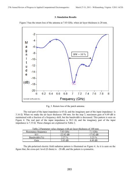
27th Annual Review of Progress in Applied Comput<strong>at</strong>ional ElectromagneticsMarch 27-31, 2011 - Williamsburg, Virginia ©2011 ACES3. Simul<strong>at</strong>ion ResultsFigure 3 has the return loss of the antenna <strong>at</strong> 7.03 <strong>GHz</strong>, when air layer thickness is 20 mm.BW = 10 %Fig. 3. Return loss of the p<strong>at</strong>ch antenna.The real part of the input impedance is 65 Ω, and the imaginary part of the input impedance is3.16 Ω. When we make the air layer thickness 100 mm. for the step 3, maximum gain of 4.49 dB ismaintained with a fraction of a frequency shift, but the bandwidth is decreased. This p<strong>at</strong>tern is seen onFigure 4. The real part of the input impedance is 50.3 Ω, and the imaginary part of the inputimpedance is 7.33 Ω. Those changes are explained in Table 2.Table 2:Parameter value changes with air layer thickness of 100 mmResonance frequency 7.03 <strong>GHz</strong> 7.1 <strong>GHz</strong>S11 -22.82 dB -17.02 dBBandwidth (%) 2.27 % 5.23 %Gain 3.03 dB 4.49 dBThe phi-polarized electric field radi<strong>at</strong>ion p<strong>at</strong>tern is illustr<strong>at</strong>ed on Figure 4. As it is seen on thefigure th<strong>at</strong>, the cross-pol. level (E-theta) is –20 dB, and the p<strong>at</strong>tern is symmetric.263