

the influence of overhung and axial loads at output shaft of universal ...
the influence of overhung and axial loads at output shaft of universal ...
the influence of overhung and axial loads at output shaft of universal ...

Create successful ePaper yourself
Turn your PDF publications into a flip-book with our unique Google optimized e-Paper software.
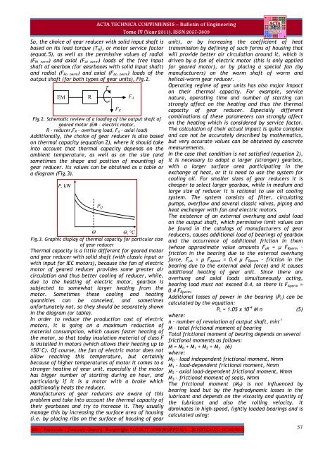
So, <strong>the</strong> choice <strong>of</strong> gear reducer with solid input <strong>shaft</strong> isbased on its load torque (T N ), or motor service factor(equ<strong>at</strong>.5), as well as <strong>the</strong> permissive values <strong>of</strong> radial(F Ri perm ) <strong>and</strong> <strong>axial</strong> (F Ai perm ) <strong>loads</strong> <strong>of</strong> <strong>the</strong> free input<strong>shaft</strong> <strong>of</strong> gearbox (for gearboxes with solid input <strong>shaft</strong>)<strong>and</strong> radial (F Ro perm ) <strong>and</strong> <strong>axial</strong> (F Ao perm ) <strong>loads</strong> <strong>of</strong> <strong>the</strong><strong>output</strong> <strong>shaft</strong> (for both types <strong>of</strong> gear units), Fig.2.EMRFig.2. Schem<strong>at</strong>ic review <strong>of</strong> a loading <strong>of</strong> <strong>the</strong> <strong>output</strong> <strong>shaft</strong> <strong>of</strong>geared motor (EM – electric motor,R – reducer,F R – <strong>overhung</strong> load, F A – <strong>axial</strong> load)Additionally, <strong>the</strong> choice <strong>of</strong> gear reducer is also basedon <strong>the</strong>rmal capacity (equ<strong>at</strong>ion 2), where it should takeinto account th<strong>at</strong> <strong>the</strong>rmal capacity depends on <strong>the</strong>ambient temper<strong>at</strong>ure, as well as on <strong>the</strong> size (<strong>and</strong>sometimes <strong>the</strong> shape <strong>and</strong> position <strong>of</strong> mounting) <strong>of</strong>gear reducer. Its values can be obtained as a table ora diagram (Fig.3).P, kWΘΘ, °CFig.3. Graphic display <strong>of</strong> <strong>the</strong>rmal capacity for particular size<strong>of</strong> gear reducerThermal capacity is a little different for geared motor<strong>and</strong> gear reducer with solid <strong>shaft</strong> (with classic input orwith input for IEC motors), because <strong>the</strong> fan <strong>of</strong> electricmotor <strong>of</strong> geared reducer provides some gre<strong>at</strong>er aircircul<strong>at</strong>ion <strong>and</strong> thus better cooling <strong>of</strong> reducer, while,due to <strong>the</strong> he<strong>at</strong>ing <strong>of</strong> electric motor, gearbox issubjected to somewh<strong>at</strong> larger he<strong>at</strong>ing from <strong>the</strong>motor. Sometimes <strong>the</strong>se cooling <strong>and</strong> he<strong>at</strong>ingquantities can be canceled, <strong>and</strong> sometimesunfortun<strong>at</strong>ely not, so <strong>the</strong>y should be separ<strong>at</strong>ely shownin <strong>the</strong> diagram (or table).In order to reduce <strong>the</strong> production cost <strong>of</strong> electricmotors, it is going on a maximum reduction <strong>of</strong>m<strong>at</strong>erial consumption, which causes faster he<strong>at</strong>ing <strong>of</strong><strong>the</strong> motor, so th<strong>at</strong> today insul<strong>at</strong>ion m<strong>at</strong>erial <strong>of</strong> class Fis installed in motors (which allows <strong>the</strong>ir he<strong>at</strong>ing up to150°C). Of course, <strong>the</strong> fan <strong>of</strong> electric motor does notallow reaching this temper<strong>at</strong>ure, but certainlybecause <strong>of</strong> higher temper<strong>at</strong>ures <strong>of</strong> motor it comes to astronger he<strong>at</strong>ing <strong>of</strong> gear unit, especially if <strong>the</strong> motorhas bigger number <strong>of</strong> starting during an hour, <strong>and</strong>particularly if it is a motor with a brake whichadditionally he<strong>at</strong>s <strong>the</strong> reducer.Manufacturers <strong>of</strong> gear reducers are aware <strong>of</strong> thisproblem <strong>and</strong> take into account <strong>the</strong> <strong>the</strong>rmal capacity <strong>of</strong><strong>the</strong>ir gearboxes <strong>and</strong> try to increase it. They usuallymanage this by increasing <strong>the</strong> surface area <strong>of</strong> housing(i.e. by placing ribs on <strong>the</strong> surface <strong>of</strong> housing <strong>of</strong> gearP QTF RF Аunit), or by increasing <strong>the</strong> coefficient <strong>of</strong> he<strong>at</strong>transmission by defining <strong>of</strong> such forms <strong>of</strong> housing th<strong>at</strong>will provide better air circul<strong>at</strong>ion around it, which isdriven by a fan <strong>of</strong> electric motor (this is only appliedfor geared motor), or by placing a special fan (bymanufacturers) on <strong>the</strong> worm <strong>shaft</strong> <strong>of</strong> worm <strong>and</strong>helical-worm gear reducer.Oper<strong>at</strong>ing regime <strong>of</strong> gear units has also major impacton <strong>the</strong>ir <strong>the</strong>rmal capacity. For example, servicen<strong>at</strong>ure, oper<strong>at</strong>ing time <strong>and</strong> number <strong>of</strong> starting canstrongly affect on <strong>the</strong> he<strong>at</strong>ing <strong>and</strong> thus <strong>the</strong> <strong>the</strong>rmalcapacity <strong>of</strong> gear reducer. Especially differentcombin<strong>at</strong>ions <strong>of</strong> <strong>the</strong>se parameters can strongly affecton <strong>the</strong> he<strong>at</strong>ing which is considered by service factor.The calcul<strong>at</strong>ion <strong>of</strong> <strong>the</strong>ir actual impact is quite complex<strong>and</strong> can not be accur<strong>at</strong>ely described by ma<strong>the</strong>m<strong>at</strong>ics,but very accur<strong>at</strong>e values can be obtained by concretemeasurements.In <strong>the</strong> case th<strong>at</strong> condition is not s<strong>at</strong>isfied (equ<strong>at</strong>ion 2),it is necessary to adopt a larger (stronger) gearbox,with a larger surface area particip<strong>at</strong>ing in <strong>the</strong>exchange <strong>of</strong> he<strong>at</strong>, or it is need to use <strong>the</strong> system forcooling oil. For smaller sizes <strong>of</strong> gear reducers it ischeaper to select larger gearbox, while in medium <strong>and</strong>large size <strong>of</strong> reducer it is r<strong>at</strong>ional to use oil coolingsystem. The system consists <strong>of</strong> filter, circul<strong>at</strong>ingpumps, overflow <strong>and</strong> several classic valves, piping <strong>and</strong>he<strong>at</strong> exchanger with fan <strong>and</strong> electric motors.The existence <strong>of</strong> an external <strong>overhung</strong> <strong>and</strong> <strong>axial</strong> loadon <strong>the</strong> <strong>output</strong> <strong>shaft</strong>, which permissive limit values canbe found in <strong>the</strong> c<strong>at</strong>alogs <strong>of</strong> manufacturers <strong>of</strong> gearreducers, causes additional load <strong>of</strong> bearings <strong>of</strong> gearbox<strong>and</strong> <strong>the</strong> occurrence <strong>of</strong> additional friction in <strong>the</strong>m(whose approxim<strong>at</strong>e value amounts F μR = μ F Rperm –friction in <strong>the</strong> bearing due to <strong>the</strong> external <strong>overhung</strong>force, F μA = μ F Aperm = 0.4 μ F Rperm – friction in <strong>the</strong>bearing due to <strong>the</strong> external <strong>axial</strong> force) <strong>and</strong> it causesadditional he<strong>at</strong>ing <strong>of</strong> gear unit. Since <strong>the</strong>re are<strong>overhung</strong> <strong>and</strong> <strong>axial</strong> <strong>loads</strong> simultaneously acting,bearing load must not exceed 0.4, so <strong>the</strong>re is F Aperm =0.4 F Rperm .Additional losses <strong>of</strong> power in <strong>the</strong> bearing (P L ) can becalcul<strong>at</strong>ed by <strong>the</strong> equ<strong>at</strong>ion:P L = 1.05 x 10 -4 M n (5)where:n – number <strong>of</strong> revolution <strong>of</strong> <strong>output</strong> <strong>shaft</strong>, min -1M – total frictional moment <strong>of</strong> bearingTotal frictional moment <strong>of</strong> bearing depends on severalfrictional moments as follows:M = M 0 + M 1 + M 2 + M 3 (6)where:M 0 – load independent frictional moment, NmmM 1 – load-dependent frictional moment, NmmM 2 – <strong>axial</strong> load-dependent frictional moment, NmmM 3 – frictional moment <strong>of</strong> seals, NmmThe frictional moment (M 0 ) is not <strong>influence</strong>d bybearing load but by <strong>the</strong> hydrodynamic losses in <strong>the</strong>lubricant <strong>and</strong> depends on <strong>the</strong> viscosity <strong>and</strong> quantity <strong>of</strong><strong>the</strong> lubricant <strong>and</strong> also <strong>the</strong> rolling velocity. Itdomin<strong>at</strong>es in high-speed, lightly loaded bearings <strong>and</strong> iscalcul<strong>at</strong>ed using:57


