Tau Neutrino Appearance via Neutrino Oscillations in Atmospheric ...
Tau Neutrino Appearance via Neutrino Oscillations in Atmospheric ...
Tau Neutrino Appearance via Neutrino Oscillations in Atmospheric ...

You also want an ePaper? Increase the reach of your titles
YUMPU automatically turns print PDFs into web optimized ePapers that Google loves.
<strong>Tau</strong> <strong>Neutr<strong>in</strong>o</strong> <strong>Appearance</strong> <strong>via</strong> <strong>Neutr<strong>in</strong>o</strong><strong>Oscillations</strong> <strong>in</strong> <strong>Atmospheric</strong> <strong>Neutr<strong>in</strong>o</strong>sA Dissertation PresentedbyTokufumi KatotoThe Graduate School<strong>in</strong> Partial Fulfillment of theRequirementsfor the Degree ofDoctor of Philosophy<strong>in</strong>PhysicsStony Brook UniversityMay 2007
Stony Brook UniversityThe Graduate SchoolTokufumi KatoWe, the dissertation committee for the above candidate for the Doctor ofPhilosophy degree, hereby recommend acceptance of the dissertation.Dr. Chang Kee JungAdvisorProfessor of Physics and AstronomyStony Brook UniversityDr. Maria Concepcion Gonzalez-GarciaChairperson of DefenseAssociate Professor of Physics and AstronomyStony Brook UniversityDr. Thomas C. We<strong>in</strong>achtAssistant Professor of Physics and AstronomyStony Brook UniversityDr. Walter TokiProfessor of PhysicsColorado State UniversityThis dissertation is accepted by the Graduate School.Lawrence Mart<strong>in</strong>Dean of the Graduate Schoolii
Abstract of the Dissertation<strong>Tau</strong> <strong>Neutr<strong>in</strong>o</strong> <strong>Appearance</strong> <strong>via</strong> <strong>Neutr<strong>in</strong>o</strong><strong>Oscillations</strong> <strong>in</strong> <strong>Atmospheric</strong> <strong>Neutr<strong>in</strong>o</strong>sbyTokufumi KatoDoctor of Philosophy<strong>in</strong>PhysicsStony Brook University2007A search for the appearance of tau neutr<strong>in</strong>os from ν µ ↔ ν τoscillations <strong>in</strong> the atmospheric neutr<strong>in</strong>os has been conducted us<strong>in</strong>gthe atmospheric neutr<strong>in</strong>o data from the Super-Kamiokande-Iand the Super-Kamiokande-II experiment. A tau neutr<strong>in</strong>o enrichedevent sample is selected by us<strong>in</strong>g the event topologies of the decayof tau leptons produced <strong>in</strong> charged-current weak <strong>in</strong>teractions.An excess of tau neutr<strong>in</strong>o signals is observed, and a best-fit tauneutr<strong>in</strong>o appearance signal of 162 ± 59 (stat.) +21−56 (sys.), whichdisfavors the no tau neutr<strong>in</strong>o appearance hypothesis by 2.1 sigma.This is consistent with the expected number of tau neutr<strong>in</strong>o events,121 ± 39 (sys.) for ∆m 2 = 2.4 × 10 −3 eV 2 , assum<strong>in</strong>g the full mix<strong>in</strong>g<strong>in</strong> ν µ ↔ ν τ oscillations. The Super-Kamiokande atmosphericneutr<strong>in</strong>o data are consistent with tau neutr<strong>in</strong>o appearance fromν µ ↔ ν τ oscillations.iii
Dedicated to my parents.
ContentsList of FiguresList of TablesAcknowledgementsviiixixiii1 Introduction 11.1 <strong>Neutr<strong>in</strong>o</strong>s . . . . . . . . . . . . . . . . . . . . . . . . . . . . . 11.2 <strong>Neutr<strong>in</strong>o</strong>s <strong>in</strong> the Standard Model . . . . . . . . . . . . . . . . 31.3 <strong>Neutr<strong>in</strong>o</strong> Mass and <strong>Neutr<strong>in</strong>o</strong> <strong>Oscillations</strong> . . . . . . . . . . . . 51.3.1 Detection of <strong>Neutr<strong>in</strong>o</strong> <strong>Oscillations</strong> . . . . . . . . . . . . 71.4 <strong>Atmospheric</strong> <strong>Neutr<strong>in</strong>o</strong>s and <strong>Neutr<strong>in</strong>o</strong> Oscillation Experiments 81.4.1 <strong>Atmospheric</strong> <strong>Neutr<strong>in</strong>o</strong>s . . . . . . . . . . . . . . . . . . 81.4.2 <strong>Neutr<strong>in</strong>o</strong> Oscillation Experiments . . . . . . . . . . . . 91.5 Super-Kamiokande . . . . . . . . . . . . . . . . . . . . . . . . 111.5.1 Super-Kamiokande Collaboration . . . . . . . . . . . . 121.6 Motivation of the analysis <strong>in</strong> this thesis . . . . . . . . . . . . . 122 Super-Kamiokande Detector 152.1 Overview . . . . . . . . . . . . . . . . . . . . . . . . . . . . . . 152.1.1 Cherenkov Radiation . . . . . . . . . . . . . . . . . . . 202.2 Water Tank: Detector . . . . . . . . . . . . . . . . . . . . . . 202.2.1 Inner Detector . . . . . . . . . . . . . . . . . . . . . . . 232.2.2 Outer Detector . . . . . . . . . . . . . . . . . . . . . . 232.3 Photomultiplier Tube (PMT) . . . . . . . . . . . . . . . . . . 242.3.1 Inner Detector PMT . . . . . . . . . . . . . . . . . . . 242.3.2 Outer Detector PMT . . . . . . . . . . . . . . . . . . . 282.4 Water Purification System . . . . . . . . . . . . . . . . . . . . 282.5 Radon Hut and Air Purification System . . . . . . . . . . . . 292.6 Electronics and Data Acquisition System (DAQ) . . . . . . . . 322.6.1 Inner Detector DAQ . . . . . . . . . . . . . . . . . . . 33v
2.6.2 Outer Detector DAQ . . . . . . . . . . . . . . . . . . . 342.6.3 Trigger System . . . . . . . . . . . . . . . . . . . . . . 372.6.4 Flash ADC . . . . . . . . . . . . . . . . . . . . . . . . 402.6.5 Offl<strong>in</strong>e Data Process . . . . . . . . . . . . . . . . . . . 403 Detector Calibration 413.1 PMT calibration . . . . . . . . . . . . . . . . . . . . . . . . . 413.1.1 Relative Ga<strong>in</strong> . . . . . . . . . . . . . . . . . . . . . . . 413.1.2 Absolute Ga<strong>in</strong> . . . . . . . . . . . . . . . . . . . . . . . 433.1.3 Relative Tim<strong>in</strong>g . . . . . . . . . . . . . . . . . . . . . . 433.2 Water Transparency Measurement . . . . . . . . . . . . . . . . 463.2.1 Light scatter<strong>in</strong>g measurement . . . . . . . . . . . . . . 493.2.2 Time variation of Water Transparency . . . . . . . . . 493.3 Absolute Energy Calibration . . . . . . . . . . . . . . . . . . . 503.3.1 Decay electron measurement . . . . . . . . . . . . . . . 543.3.2 <strong>Neutr<strong>in</strong>o</strong>-<strong>in</strong>duced π 0 measurement . . . . . . . . . . . . 543.3.3 Cosmic ray stopp<strong>in</strong>g muon measurement . . . . . . . . 573.3.4 Time variation of energy scale . . . . . . . . . . . . . . 583.4 Calibrations for low energy events . . . . . . . . . . . . . . . . 594 Simulation 614.1 <strong>Atmospheric</strong> <strong>Neutr<strong>in</strong>o</strong>s . . . . . . . . . . . . . . . . . . . . . 614.2 <strong>Neutr<strong>in</strong>o</strong> Interactions (Cross Section) . . . . . . . . . . . . . . 684.2.1 Elastic and Quasi-elastic Scatter<strong>in</strong>g . . . . . . . . . . . 694.2.2 Resonant S<strong>in</strong>gle-Meson Production . . . . . . . . . . . 704.2.3 Deep-<strong>in</strong>elastic Scatter<strong>in</strong>g . . . . . . . . . . . . . . . . . 724.2.4 Coherent Pion Production . . . . . . . . . . . . . . . . 754.2.5 Nuclear Effect . . . . . . . . . . . . . . . . . . . . . . . 774.3 Detector Simulation (Particle Track<strong>in</strong>g) . . . . . . . . . . . . . 804.4 <strong>Tau</strong> <strong>Neutr<strong>in</strong>o</strong>s Simulation . . . . . . . . . . . . . . . . . . . . 825 Data Reduction 865.1 Event Class . . . . . . . . . . . . . . . . . . . . . . . . . . . . 865.2 Reduction for Fully Conta<strong>in</strong>ed Sample . . . . . . . . . . . . . 885.2.1 First Reduction . . . . . . . . . . . . . . . . . . . . . . 885.2.2 Second Reduction . . . . . . . . . . . . . . . . . . . . . 905.2.3 Third Reduction . . . . . . . . . . . . . . . . . . . . . 905.2.4 Fourth Reduction . . . . . . . . . . . . . . . . . . . . . 935.2.5 Fifth Reduction . . . . . . . . . . . . . . . . . . . . . . 935.2.6 Fully Conta<strong>in</strong>ed Cut . . . . . . . . . . . . . . . . . . . 94vi
6 Event Reconstruction 966.1 Vertex Fitt<strong>in</strong>g . . . . . . . . . . . . . . . . . . . . . . . . . . . 966.2 R<strong>in</strong>g Count<strong>in</strong>g . . . . . . . . . . . . . . . . . . . . . . . . . . . 976.3 Particle Identification . . . . . . . . . . . . . . . . . . . . . . . 1016.4 Precise Vertex Fitt<strong>in</strong>g (MS-fit) . . . . . . . . . . . . . . . . . . 1026.5 Momentum Reconstruction . . . . . . . . . . . . . . . . . . . . 1066.6 R<strong>in</strong>g Correction . . . . . . . . . . . . . . . . . . . . . . . . . . 1067 <strong>Tau</strong> <strong>Neutr<strong>in</strong>o</strong> <strong>Appearance</strong> Analysis 1077.1 Overview . . . . . . . . . . . . . . . . . . . . . . . . . . . . . . 1077.2 Data and MC set . . . . . . . . . . . . . . . . . . . . . . . . . 1087.3 <strong>Tau</strong> <strong>Neutr<strong>in</strong>o</strong> Events . . . . . . . . . . . . . . . . . . . . . . . 1117.4 Variables for Dist<strong>in</strong>guish<strong>in</strong>g tau-like events . . . . . . . . . . . 1127.5 The Likelihood . . . . . . . . . . . . . . . . . . . . . . . . . . 1137.6 Zenith Angle Fit . . . . . . . . . . . . . . . . . . . . . . . . . 1197.7 Zenith angle fit with SK-I and SK-II data . . . . . . . . . . . 1237.8 Systematic Uncerta<strong>in</strong>ties . . . . . . . . . . . . . . . . . . . . . 1237.8.1 Systematic Uncerta<strong>in</strong>ties <strong>in</strong> <strong>Atmospheric</strong> <strong>Neutr<strong>in</strong>o</strong> Flux 1257.8.2 Systematic Uncerta<strong>in</strong>ties <strong>in</strong> <strong>Neutr<strong>in</strong>o</strong> Interactions . . . 1267.8.3 Systematic Uncerta<strong>in</strong>ties <strong>in</strong> Event Selection . . . . . . 1287.8.4 Systematic Uncerta<strong>in</strong>ties <strong>in</strong> Event Reconstruction . . . 1287.8.5 Systematic Uncerta<strong>in</strong>ties <strong>in</strong> ν τ <strong>Appearance</strong> analysis . . 1297.8.6 Systematic Uncerta<strong>in</strong>ties <strong>in</strong> Oscillation Parameters . . 1307.9 Results . . . . . . . . . . . . . . . . . . . . . . . . . . . . . . . 1368 Conclusions and Future 1378.1 Conclusions . . . . . . . . . . . . . . . . . . . . . . . . . . . . 1378.2 Future . . . . . . . . . . . . . . . . . . . . . . . . . . . . . . . 137A Super-Kamiokande Accident and SK-II and SK-III 139A.1 Super-Kamiokande Accident . . . . . . . . . . . . . . . . . . . 139A.1.1 Cause . . . . . . . . . . . . . . . . . . . . . . . . . . . 140A.1.2 PMT case . . . . . . . . . . . . . . . . . . . . . . . . . 140A.2 Super-Kamiokande-II . . . . . . . . . . . . . . . . . . . . . . . 141A.3 Super-Kamiokande-III . . . . . . . . . . . . . . . . . . . . . . 141B Energy Flow Analysis 142B.1 Geodesic b<strong>in</strong>n<strong>in</strong>g . . . . . . . . . . . . . . . . . . . . . . . . . 142B.1.1 Charge Flux . . . . . . . . . . . . . . . . . . . . . . . . 142B.2 Energy Flow . . . . . . . . . . . . . . . . . . . . . . . . . . . . 143vii
B.3 Event Shape Variables . . . . . . . . . . . . . . . . . . . . . . 146Bibliography 147viii
List of Figures1.1 Feynman diagrams of weak <strong>in</strong>teractions . . . . . . . . . . . . . 41.2 Survival and oscillation probability . . . . . . . . . . . . . . . 71.3 <strong>Atmospheric</strong> neutr<strong>in</strong>o production . . . . . . . . . . . . . . . . 91.4 Allowed region of s<strong>in</strong> 2 2θ and ∆m 2 from SK, K2K and MINOSexperiments . . . . . . . . . . . . . . . . . . . . . . . . . . . . 111.5 The zenith angle distributions from Super-Kamiokande . . . . 131.6 The L/E distribution from Super-Kamiokande . . . . . . . . . 142.1 The location of the Super-Kamiokande detector <strong>in</strong> Japan . . . 162.2 The Super-Kamiokande detector . . . . . . . . . . . . . . . . . 182.3 A side-view of the Super-Kamiokande detector . . . . . . . . . 192.4 Cherenkov Radiation . . . . . . . . . . . . . . . . . . . . . . . 212.5 PMT mount<strong>in</strong>g structure . . . . . . . . . . . . . . . . . . . . . 222.6 Inner Detector photomultiplier tube . . . . . . . . . . . . . . . 242.7 Chrenkov spectrum and Quantum Efficiency of an ID PMT . . 252.8 ID PMT: Quantum Efficiency . . . . . . . . . . . . . . . . . . 262.9 ID PMT: Energy resolution . . . . . . . . . . . . . . . . . . . 262.10 ID PMT: Tim<strong>in</strong>g resolution . . . . . . . . . . . . . . . . . . . 272.11 Water purification system . . . . . . . . . . . . . . . . . . . . 302.12 Radon levels <strong>in</strong> the m<strong>in</strong>e air . . . . . . . . . . . . . . . . . . . 312.13 Air Purification System . . . . . . . . . . . . . . . . . . . . . . 332.14 Analog-Tim<strong>in</strong>g-Module (ATM) . . . . . . . . . . . . . . . . . 352.15 Analog <strong>in</strong>put of the ATM for one channel . . . . . . . . . . . . 352.16 Inner Detector DAQ . . . . . . . . . . . . . . . . . . . . . . . 362.17 ID trigger scheme . . . . . . . . . . . . . . . . . . . . . . . . . 372.18 Outer Detector DAQ . . . . . . . . . . . . . . . . . . . . . . . 383.1 Xe calibration system for the ID PMT relative ga<strong>in</strong> measurement 423.2 Relative photo-sensitivity of the ID PMTs . . . . . . . . . . . 433.3 Relative ga<strong>in</strong> distribution for ID PMTs . . . . . . . . . . . . . 443.4 Ni-Cf calibration system . . . . . . . . . . . . . . . . . . . . . 44ix
3.5 S<strong>in</strong>gle photo-electron charge distribution for ID PMT . . . . . 453.6 Laser calibration system for relative tim<strong>in</strong>g . . . . . . . . . . . 463.7 TQ-map: PMT tim<strong>in</strong>g response vs charge . . . . . . . . . . . 473.8 Tim<strong>in</strong>g resolution of the ID PMT . . . . . . . . . . . . . . . . 483.9 Laser calibration system for water transparency . . . . . . . . 503.10 Time distributions of the hit PMTs. . . . . . . . . . . . . . . . 513.11 Attenuation length coefficient . . . . . . . . . . . . . . . . . . 523.12 Attenuation length measured by cosmic ray muons . . . . . . 523.13 Time variation of water attenuation length . . . . . . . . . . . 533.14 Energy spectrum of decay electrons . . . . . . . . . . . . . . . 553.15 Distribution of neutr<strong>in</strong>o-<strong>in</strong>duced π 0 <strong>in</strong>variant mass . . . . . . . 563.16 low energy stopp<strong>in</strong>g muons . . . . . . . . . . . . . . . . . . . . 573.17 Ratio of the momentum to the range for high energy stopp<strong>in</strong>gmuons . . . . . . . . . . . . . . . . . . . . . . . . . . . . . . . 583.18 Absolute energy scale calibration . . . . . . . . . . . . . . . . 593.19 Time variation of the energy scale . . . . . . . . . . . . . . . . 604.1 Primary cosmic ray proton flux . . . . . . . . . . . . . . . . . 634.2 The rigidity cutoff at the Kamioka site . . . . . . . . . . . . . 644.3 The flux of cosmic ray muons . . . . . . . . . . . . . . . . . . 644.4 The absolute flux and the flavor ratio of the atmospheric neutr<strong>in</strong>os 664.5 The atmospheric neutr<strong>in</strong>o flux vs zenith angle. . . . . . . . . . 674.6 Cross section of quasi-elastic scatter<strong>in</strong>g . . . . . . . . . . . . . 714.7 Cross section of charged current resonant s<strong>in</strong>gle-meson production 734.8 Cross section of neutral current resonant s<strong>in</strong>gle-meson production 744.9 Total charge current cross section divided by E ν . . . . . . . . 764.10 Cross section of coherent pion production . . . . . . . . . . . . 784.11 Cross section of π + - 16 O <strong>in</strong>teractions . . . . . . . . . . . . . . . 794.12 Cross section of charged current ν τ and ν τ <strong>in</strong>teractions . . . . 834.13 Cross section for CC ν τ , ν µ , ν e and ν τ , ν µ , ν e <strong>in</strong>teractions . . . 845.1 <strong>Atmospheric</strong> <strong>Neutr<strong>in</strong>o</strong> Event Classes and their Energy Ranges 875.2 Fully conta<strong>in</strong>ed data reduction . . . . . . . . . . . . . . . . . . 896.1 R<strong>in</strong>g f<strong>in</strong>d<strong>in</strong>g algorithm . . . . . . . . . . . . . . . . . . . . . . 986.2 Charge map from Hough Transformation algorithm . . . . . . 996.3 R<strong>in</strong>g-count<strong>in</strong>g likelihood distribution . . . . . . . . . . . . . . 1006.4 R<strong>in</strong>g-count<strong>in</strong>g likelihood distribution for SK-II . . . . . . . . . 1016.5 Event display of electron and muon neutr<strong>in</strong>o events . . . . . . 1036.6 PID likelihood distributions for SK-I . . . . . . . . . . . . . . 104x
6.7 PID likelihood distributions for SK-II . . . . . . . . . . . . . . 1057.1 Energy spectrum of the FC CC/NC atmospheric neutr<strong>in</strong>o andCC ν τ events . . . . . . . . . . . . . . . . . . . . . . . . . . . 1097.2 Event display of tau neutr<strong>in</strong>o MC event . . . . . . . . . . . . . 1107.3 The distribution of likelihood variables for SK-I . . . . . . . . 1147.4 The distribution of likelihood variables for SK-II . . . . . . . . 1157.5 The distribution of the number of r<strong>in</strong>gs <strong>in</strong> SK-I and SK-II . . 1167.6 Likelihood distribution for SK-I . . . . . . . . . . . . . . . . . 1177.7 Likelihood distribution for SK-II . . . . . . . . . . . . . . . . . 1187.8 Likelihood cut sensitivity . . . . . . . . . . . . . . . . . . . . . 1197.9 The zenith angle distribution for SK-I . . . . . . . . . . . . . . 1217.10 The zenith angle distribution for SK-II . . . . . . . . . . . . . 1227.11 The zenith angle distributions for SK-I and SK-II comb<strong>in</strong>ed fit 124B.1 Geodesic splits . . . . . . . . . . . . . . . . . . . . . . . . . . 143B.2 Subdivision of an icosahedron . . . . . . . . . . . . . . . . . . 144xi
List of Tables1.1 Elementary particles and forces <strong>in</strong> the Standard Model . . . . 41.2 Flavor ratio R(µ/e) . . . . . . . . . . . . . . . . . . . . . . . . 102.1 Inner Detector PMT characteristics . . . . . . . . . . . . . . . 274.1 Processes considered <strong>in</strong> the detector simulation . . . . . . . . 814.2 Branch<strong>in</strong>g Ratio of tau lepton decay . . . . . . . . . . . . . . 855.1 Fully-conta<strong>in</strong>ed Event Summary for Data and MC . . . . . . . 957.1 Branch<strong>in</strong>g Ratio of tau lepton decay . . . . . . . . . . . . . . 1087.2 Data and MC sets for SK-I and SK-II ν τ appearance analysis . 1117.3 Event selection for SK-I . . . . . . . . . . . . . . . . . . . . . 1177.4 Event selection for SK-II . . . . . . . . . . . . . . . . . . . . . 1187.5 Interaction modes <strong>in</strong> the atmospheric neutr<strong>in</strong>o background events1207.6 Summary of zenith angle fit . . . . . . . . . . . . . . . . . . . 1217.7 Systematic uncerta<strong>in</strong>ties <strong>in</strong> neutr<strong>in</strong>o flux and neutr<strong>in</strong>o <strong>in</strong>teractions1317.8 Systematic uncerta<strong>in</strong>ties <strong>in</strong> event selection and reconstruction 1327.9 Systematic uncerta<strong>in</strong>ties <strong>in</strong> event selection and reconstruction 1337.10 Systematic uncerta<strong>in</strong>ties <strong>in</strong> oscillation parameters . . . . . . . 1347.11 Systematic uncerta<strong>in</strong>ties <strong>in</strong> solar activity . . . . . . . . . . . . 1347.12 Summary of systematic uncerta<strong>in</strong>ties . . . . . . . . . . . . . . 135A.1 Summary of the damage <strong>in</strong> the ID of Super-Kamiokande . . . 139A.2 Summary of the damage <strong>in</strong> the ID of Super-Kamiokande . . . 140A.3 Super-Kamiokande-I, II, and III . . . . . . . . . . . . . . . . . 141xii
AcknowledgementsAfter spend<strong>in</strong>g six years <strong>in</strong> graduate school, I owe a debt of gratitude tomany people. Without their support, this thesis could never have reachedcompletion.First, I would like to thank my advisor, Chang Kee Jung. I have beenhis student for a long time. I came to Stony Brook as a sophomore studentand soon jo<strong>in</strong>ed his research group (Stony Brook Nucleon decay and <strong>Neutr<strong>in</strong>o</strong>(NN) Group). Chang Kee gave me a great opportunity to work on both Super-Kamiokande and K2K experiments. In my senior year when I was consider<strong>in</strong>gwhich graduate schools to apply for, Chang Kee k<strong>in</strong>dly asked me if I wouldhave wanted to stay <strong>in</strong> Stony Brook for graduate study. Because a thesisexperiment (Super-Kamiokande) was very <strong>in</strong>terest<strong>in</strong>g and because I was surethat it would have been hard to f<strong>in</strong>d a better advisor than Chang Kee, Idecided to stay and cont<strong>in</strong>ued work<strong>in</strong>g <strong>in</strong> Chang Kee’s group. I must say howlucky I am to have been work<strong>in</strong>g with Chang Kee. He gave me his advicenot only to be a good physicist but also to be a f<strong>in</strong>e person. Chang Kee’sdedication to physics and education, vision, care, patience, and criticism issimply someth<strong>in</strong>g I give a great respect for and someth<strong>in</strong>g I strive for.I owe a large debt to Clark McGrew. He has directly helped me withmy analysis work s<strong>in</strong>ce Clark is the one who orig<strong>in</strong>ally started tau neutr<strong>in</strong>oappearance analysis at Super-K. I would like to thank Clark for <strong>in</strong>valuablediscussions on physics as well as statistics with his unique humor.Besides Chang Kee and Clark, I also want to thank the other membersof the NN group, Chiaki Yanagisawa, Peter Paul, Antony Sarrat and KenkouKobayashi for their help and guidance. Although I did not spent much timetogether, I would like to thank the former NN group students; Brett Viren,Eric Sharkey, Christopher Mauger, Matthew Malek, and Markus Ackermanfor their assistant and advice. Brett was my mentor, who taught me particlephysics and L<strong>in</strong>ux with great patience. I was very happy to have had himwhen I jo<strong>in</strong>ed the NN group without any knowledge about do<strong>in</strong>g research <strong>in</strong>particle physics or computer skills. I thank my fellow NN group students whojo<strong>in</strong>ed the NN group after me; Ryan Terri, Lisa Whitehead, Le Phuoc Trung,
Glenn Lopez, and Dima Beznosko for their friendship and good memories fromthe nights when we went out for a few dr<strong>in</strong>ks.I am happy to have Concha Gonzalez-Garcia, Tom We<strong>in</strong>acht, and WalterToki as committee members. They gave me good feedbacks and comments,which were <strong>in</strong>corporated <strong>in</strong>to this thesis. I thank Walter for fly<strong>in</strong>g from Coloradoto NY to be at my defense.I am grateful to our spokesperson of the Super-Kamiokande experiment,Yoichiro Suzuki for show<strong>in</strong>g his leadership. I was <strong>in</strong> the atmospheric neutr<strong>in</strong>o(ATMPD) group, which has been led by Takaaki Kajita and Ed Kearns. Withtheir generous effort, this group is well organized, and physics analyses havebeen conducted smoothly.I would like to thank all of the members <strong>in</strong> the tau neutr<strong>in</strong>o appearanceanalysis group; Takaaki Kajita, Ed Kearns, Chang Kee Jung, Clark McGrew,Chris Walter, and Choji Saji for numerous <strong>in</strong>valuable discussions and theirguidance as well as their great contributions to this thesis. Work<strong>in</strong>g <strong>in</strong> thisgroup has been a pleasure. In particular, I have worked very closely withChoji Saji on the analysis and would like to thank him for his help withendless patience. We became good friends and went snowboard<strong>in</strong>g togethermany times.I would also like to s<strong>in</strong>cerely thank Masato Shiozawa and Yusuke Koshiofor important discussions as well as their technical support. I have been benefittedvery much from those discussions. I would like to thank Shoei Nakayamaand Masaki Ishitsuka for their great help on Super-K software and their friendship.I would have had much more difficult time <strong>in</strong> my analysis work withouttheir support. I also want to thank Masayuki Nakahata, Bill Kropp, KenjiKaneyuki, Shigetaka Moriyama, Yasuo Takeuchi, Mark Vag<strong>in</strong>s, Makoto Miura,Kimihiro Okumura, Yosh<strong>in</strong>ari Hayato, Yoshihisa Obayashi, Jun Kameda, ItaruHiguchi, Seo Hyun Kwan, Yumiko Takenaga for their assistance.I have spent a good amount of time at Super-K work<strong>in</strong>g with graduatestudents from other US <strong>in</strong>stitutions. I would like to give my thanks to ParkerCravens from UCI, Wei Wang and Aaron Herfurth from BU, Yosh Shiraishifrom UW for their friendship and companion. While I was stay<strong>in</strong>g at Super-Kfor a long time, Parker and I often went to Izakaya for beer.Also, I would like to express my gratitude to Peter Kahn, who is a professorat Stony Brook. Peter orig<strong>in</strong>ally <strong>in</strong>troduced Chang Kee to me before I jo<strong>in</strong>edthe NN group. Peter has e-mailed me once <strong>in</strong> a while to f<strong>in</strong>d out how I wasdo<strong>in</strong>g and took me out for lunch when I was <strong>in</strong> Stony Brook.Although they did not contribute to this thesis directly, I would like tothank all of my friends <strong>in</strong> Stony Brook. Without them, my graduate lifewould have been really bor<strong>in</strong>g.
I would like to thank adm<strong>in</strong>istrative staff, Joan Napolitano and AliceDugan <strong>in</strong> the Stony Brook High Energy Group, Pat Peiliker and Diane Siegel<strong>in</strong> the department of Physics and Astronomy, and Kiyoko Hirose, Eri Okada,and Yukari Maeda <strong>in</strong> Super-K. I am grateful for their help.F<strong>in</strong>ally, I must give my thanks to my family. I wish to thank Keishi Katofor his advice and support as my father and as a scientist. I decided to studyphysics because of his <strong>in</strong>fluences. I would also like to thank my mother, YokoKato for her sacrifices and support. Without their encouragement and trust, Icould never have made through graduate school and come to this po<strong>in</strong>t. Thankyou very much.
1Chapter 1Introduction1.1 <strong>Neutr<strong>in</strong>o</strong>s<strong>Neutr<strong>in</strong>o</strong>s are everywhere and are one of the most common particles aroundus, yet we know the least about them. This elusive particle comes from manydifferent sources, such as human body <strong>via</strong> the β-decay of 40 K to 39 K, naturalradioactive materials on the Earth, nuclear reactors around the world, theupper atmosphere of the Earth, the Sun, and the Universe (e.g. Supernovaeand the Big Bang). Although neutr<strong>in</strong>os are abundant <strong>in</strong> nature, they wereonly first postulated theoretically by Wolfgang Pauli <strong>in</strong> 1930 [1]. In β-decay,the measured energy spectrum of the emitted electrons was cont<strong>in</strong>uous <strong>in</strong>steadof the expected monoenergetic distribution <strong>in</strong> two body decay. This observationseemed to violate the law of energy conservation. As a solution to theproblem, Pauli proposed that there could exist another neutral particle emitted<strong>in</strong> β-decay, which carried away the miss<strong>in</strong>g energy and made the electronenergy spectrum cont<strong>in</strong>uous. He wrote his famous letter, “Liebe RadioaktiveDamen und Herren (Dear Radioactive Ladies and Gentlemen”to the Tub<strong>in</strong>gencongress on 4th December 1930.Dear Radioactive Ladies and Gentlemen,As the bearer of these l<strong>in</strong>es, to whom I graciously ask you to listen,will expla<strong>in</strong> to you <strong>in</strong> more detail, how because of the ”wrong”statistics of the N and 6 Li nuclei and the cont<strong>in</strong>uous beta spectrum,I have hit upon a desperate remedy to save the ”exchange theorem”of statistics and the law of conservation of energy. Namely,the possibility that there could exist <strong>in</strong> the nuclei electrically neutralparticles, that I wish to call neutrons 1 , which have sp<strong>in</strong> 1/21 This is what he called the neutr<strong>in</strong>o when he first came up with the idea. The
2and obey the exclusion pr<strong>in</strong>ciple and which further differ from lightquanta <strong>in</strong> that they do not travel with the velocity of light. Themass of the neutrons should be of the same order of magnitudeas the electron mass and <strong>in</strong> any event not larger than 0.01 protonmasses. The cont<strong>in</strong>uous beta spectrum would then becomeunderstandable by the assumption that <strong>in</strong> beta decay a neutronis emitted <strong>in</strong> addition to the electron such that the sum of theenergies of the neutron and the electron is constant...I agree that my remedy could seem <strong>in</strong>credible because oneshould have seen those neutrons very earlier if they really exist.But only the one who dare can w<strong>in</strong> and the difficult situation,due to the cont<strong>in</strong>uous structure of the beta spectrum, is lightedby a remark of my honoured predecessor, Mr Debye, who told merecently <strong>in</strong> Bruxelles: ”Oh, It’s well better not to th<strong>in</strong>k to thisat all, like new taxes”. From now on, every solution to the issuemust be discussed. Thus, dear radioactive people, look and judge.Unfortunately, I cannot appear <strong>in</strong> Tub<strong>in</strong>gen personally s<strong>in</strong>ce I am<strong>in</strong>dispensable here <strong>in</strong> Zurich because of a ball on the night of 6/7December. With my best regards to you, and also to Mr Back.Your humble servant. W. PauliEnrico Fermi named this particle the “neutr<strong>in</strong>o” mean<strong>in</strong>g a little neutralobject <strong>in</strong> Italian represented by a Greek alphabet ν. The neutr<strong>in</strong>o was <strong>in</strong>corporated<strong>in</strong> his successful theory of β-decay [3].It took 25 years until the existence of neutr<strong>in</strong>os was verified experimentally.In 1956, the neutr<strong>in</strong>o was discovered by Frederick Re<strong>in</strong>es and ClydeL. Cowan [2, 4]. The experiment 2 took place at the Savannah River nuclearreactor <strong>in</strong> South Carol<strong>in</strong>a, where the neutr<strong>in</strong>os were detected from the <strong>in</strong>verseβ-decay reaction of the neutron :p + ¯ν e → n + e + (1.1)The detector consisted of a water tank with dissolved CdCl 2 surrounded byliquid sc<strong>in</strong>tillator. They detected the co<strong>in</strong>cidence of gamma rays from pairneutron that we now know was discovered by Chadwich <strong>in</strong> 1932. What we presentlycall neutron had not yet been discovered so the name was available for this use.Enrico Fermi later proposed the now accepted name of neutr<strong>in</strong>o.2 Their first plan was to detect neutr<strong>in</strong>os emitted from a nuclear explosion.
3annihilation of a positron and a subsequent gamma ray from the neutroncapture. Re<strong>in</strong>es was awarded the Nobel Prize <strong>in</strong> 1995 for this discovery.In 1959, Bruno Pontecorvo postulated the existence of muon neutr<strong>in</strong>os (ν µ )different from the neutr<strong>in</strong>os emitted <strong>in</strong> the β-decay of nuclei. In 1962, LeonLederman, Melv<strong>in</strong> Schwartz and Jack Ste<strong>in</strong>berger discovered muon neutr<strong>in</strong>osby detect<strong>in</strong>g muons from the follow<strong>in</strong>g <strong>in</strong>teractions :ν µ + N → µ − + X (1.2)us<strong>in</strong>g a neutr<strong>in</strong>o beam at the Brookhaven National Laboratory (BNL). Fortheir discovery, they were awarded the Nobel Prize <strong>in</strong> 1988. The discoveryof the tau lepton (τ) <strong>in</strong> 1975 [5] implied the existence of the third family ofneutr<strong>in</strong>o, the tau neutr<strong>in</strong>o (ν τ ). In 2000, the tau neutr<strong>in</strong>o was directly observedby the DONUT experiment at the Fermi National Accelerator Laboratory(FNAL) as expected [6].Discovery of the neutr<strong>in</strong>os from outer space followed the discoveries ofthree generations of neutr<strong>in</strong>os. In 1968, the neutr<strong>in</strong>os from the Sun wereobserved by Ray Davis and his collaboration [7]. The neutr<strong>in</strong>os from thesupernova explosion SN1987a were observed by the Kamiokande [8, 9] andIMB [10, 11] experiments <strong>in</strong> 1987. Raymond Davis Jr. and Masatoshi Koshibawere awarded the Nobel Prize <strong>in</strong> 2002 for their discovery of cosmic neutr<strong>in</strong>os.1.2 <strong>Neutr<strong>in</strong>o</strong>s <strong>in</strong> the Standard ModelIn the Standard Model of particle physics, all elementary particles arecategorized <strong>in</strong>to two groups: fermions and bosons. Among fermions, there arequarks and leptons, which come <strong>in</strong> three generations or flavors, and the bosonsact as force mediators for strong, electromagnetic, and weak <strong>in</strong>teractions asshown <strong>in</strong> Table 1.1. <strong>Neutr<strong>in</strong>o</strong>s have three flavors : ν e , ν µ , and ν τ and arepaired with their correspond<strong>in</strong>g charged lepton, the electron, the muon, andthe tau. The number of light neutr<strong>in</strong>o flavors are confirmed to be three byLEP experiment [12].S<strong>in</strong>ce neutr<strong>in</strong>os are electrically neutral and colorless 3 , they <strong>in</strong>teract onlythrough the weak force. There are two types of weak <strong>in</strong>teractions: chargedcurrent (CC) and neutral current (NC) <strong>in</strong>teractions. The force mediators forCC and NC <strong>in</strong>teractions are the charged W and neutral Z bosons, respectively.Figure 1.1 shows example Feynman diagrams of the CC and NC <strong>in</strong>teractions.3 Only quarks have color charges to participate <strong>in</strong> strong <strong>in</strong>teractions.
4Table 1.1: Table of elementary particles and forces <strong>in</strong> the Standard Model.Particles Flavor ChargeQuarku c td s b+ 2 3− 1 3Leptone µ τ -1ν e ν µ ν τ 0Force Strong Electromagnetic WeakMediator gluon photon W and Zν e , ν µ , ν τN ′e, µ, τν e , ν µ , ν τν e , ν µ , ν τN ′W ±Z 0NNFigure 1.1: The feynman diagrams of the weak CC (left) and NC (right)<strong>in</strong>teractions of neutr<strong>in</strong>os with a nucleon (N, N’).
5In the SM, neutr<strong>in</strong>os are considered to be massless. One implies that allneutr<strong>in</strong>os are left-handed and all anti-neutr<strong>in</strong>os are right-handed characterizedby the helicity. <strong>Neutr<strong>in</strong>o</strong>’s helicity was measured by M. Goldhaber et al. [13].1.3 <strong>Neutr<strong>in</strong>o</strong> Mass and <strong>Neutr<strong>in</strong>o</strong> <strong>Oscillations</strong>Despite the masslessness of neutr<strong>in</strong>os <strong>in</strong> the SM, the mass of neutr<strong>in</strong>oshave been questioned s<strong>in</strong>ce Fermi developed his theory of neutr<strong>in</strong>os. Severalexperiments have attempted to measure the mass of ν e , ν µ , and ν τ directly <strong>via</strong>β-decay, pion decay, and τ-lepton decay respectively, but were only successfulto set the upper limits to m νe < 2.2 eV [14, 15], m νµ < 170 keV [16], m ντ
6then, |ν α (t)〉 can be expressed <strong>in</strong> the basis of weak flavor |ν β 〉 :|ν α (t)〉 = ∑ β3∑U βi e −iEit Uαi ∗ |ν β〉 (1.6)i=1The amplitude of ν α → ν β transitions at time t is :3∑A να→ν β(t) = 〈ν β |ν α (t)〉 = U βi e −iEit Uαi ∗ (1.7)i=1The probability of ν α → ν β transition is given by :P να→ν β= |A να→ν β(t)| 2 3∑2=U∣ βi e −iEit Uαi∗ ∣i=1. (1.8)In the analysis presented <strong>in</strong> this thesis, the two flavor neutr<strong>in</strong>o oscillationsare assumed, where there are two mass eigenstates and two flavor eigenstateswith a s<strong>in</strong>gle mix<strong>in</strong>g angle. In this assumption, the MNS matrix is written <strong>in</strong>terms of a mix<strong>in</strong>g angle θ :( )cos θ s<strong>in</strong> θU =(1.9)− s<strong>in</strong> θ cos θAnd, the flavor oscillation probability is given by :( 1.27∆mP (ν α → ν β ) = s<strong>in</strong> 2 2θ s<strong>in</strong> 2 2 (eV 2 ))L(km)E ν (GeV)(1.10)where θ is the neutr<strong>in</strong>o mix<strong>in</strong>g angle, ∆m 2 ≡ m 2 j − m2 i is the mass-squareddifference of neutr<strong>in</strong>o mass eigenstates <strong>in</strong> eV 2 , L is the distance traveled byneutr<strong>in</strong>os <strong>in</strong> km, E ν is neutr<strong>in</strong>o energy <strong>in</strong> GeV, and the factor 1.27 comesfrom 1/¯hc <strong>in</strong> the conversion of units to km and GeV. The survival oscillationprobability P (ν α → ν α ) is simply P (ν α → ν α ) = 1 − P (ν α → ν β ), that is :( 1.27∆mP (ν α → ν α ) = 1 − s<strong>in</strong> 2 2θ s<strong>in</strong> 2 2 (eV 2 ))L(km)E ν (GeV)(1.11)Figure 1.2 shows the survival probability and oscillation probability as a functionof L(km)/E(GeV).The neutr<strong>in</strong>o oscillation discussed <strong>in</strong> this thesis concerns ν µ ↔ ν τ oscillations.Therefore, the flavor term is (α, β) = (µ, τ) and the mass term is(i, j) = (2, 3) throughout the thesis unless mentioned specifically otherwise.
7Probability10.80.6P(ν α → ν α )P(ν α → ν β )0.40.201 10 10 2 10 3 10 4L/E (km/GeV)Figure 1.2: The survival P (ν α → ν α ) (solid l<strong>in</strong>e) and oscillation P (ν α → ν β )(dotted l<strong>in</strong>e) probability for s<strong>in</strong> 2 2θ = 1 and ∆m 2 = 2.4×10 −3 eV 2 as a functionof L(km)/E(GeV).1.3.1 Detection of <strong>Neutr<strong>in</strong>o</strong> <strong>Oscillations</strong>The oscillation parameters, a mix<strong>in</strong>g angle θ and the mass-squared difference∆m 2 , are measured with known neutr<strong>in</strong>o path length L and energy E <strong>in</strong>neutr<strong>in</strong>o oscillation experiments (Eq. 1.10 and Eq. 1.11). If there is no mix<strong>in</strong>g(θ = 0) and/or (∆m 2 L/E) ≪ 1, the oscillation probability becomes zero andhence null<strong>in</strong>g all oscillations.There are two ways to detect neutr<strong>in</strong>o oscillations of ν α → ν β . The firsttechnique is to detect ν β <strong>in</strong> a known neutr<strong>in</strong>o flux of ν α , which is known as the“appearance” of ν β . For example, <strong>in</strong> a test of ν µ ↔ ν τ oscillation hypothesis, ν τis detected <strong>in</strong> the ν µ flux. S<strong>in</strong>ce neutr<strong>in</strong>os are observed by detect<strong>in</strong>g the chargedlepton produced <strong>in</strong> their CC <strong>in</strong>teractions, they must have sufficient energy toproduce the lepton. Thus, the energy of ν τ must be greater than 3.5 GeV toproduce τ-leptons through ν τ <strong>in</strong>teractions with a fixed target nucleon. Wewould then look for τ-lepton events.The second technique is to observe “disappearance”, where the detectedneutr<strong>in</strong>o flux of ν α is less than the expected flux <strong>in</strong> the absence of oscillations.In the previous example of ν µ ↔ ν τ oscillations, if the energy of ν τ is lessthan the threshold of τ-lepton production, <strong>in</strong>stead of the observation of ν τ ,the depletion of ν µ would be an evidence for such oscillations.
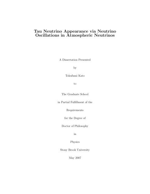
8As described <strong>in</strong> the next section, the positive signatures for the atmosphericneutr<strong>in</strong>o oscillations of ν µ ↔ ν τ was observed through ν µ disappearance byvarious experiments. In this thesis, an analysis to search for ν τ appearance isdescribed <strong>in</strong> detail.1.4 <strong>Atmospheric</strong> <strong>Neutr<strong>in</strong>o</strong>s and <strong>Neutr<strong>in</strong>o</strong> OscillationExperimentsUs<strong>in</strong>g atmospheric neutr<strong>in</strong>os produced <strong>in</strong> the atmosphere of the Earth,several experiments have studied neutr<strong>in</strong>o oscillations. In 1998, the firstcompell<strong>in</strong>g evidence for neutr<strong>in</strong>o oscillations was announced by the Super-Kamiokande collaboration [45]. The results from other experiments are alsoconsistent with Super-K, and all observations favor ν µ ↔ ν τ oscillations <strong>in</strong> theatmospheric neutr<strong>in</strong>os.1.4.1 <strong>Atmospheric</strong> <strong>Neutr<strong>in</strong>o</strong>s<strong>Atmospheric</strong> neutr<strong>in</strong>os are produced through cascade of <strong>in</strong>teractions orig<strong>in</strong>at<strong>in</strong>gfrom cosmic rays bombard<strong>in</strong>g the atmosphere nuclei. When primarycosmic rays (mostly protons and helium) from the space travel through theatmosphere of the Earth, they <strong>in</strong>teract with air nuclei such as nitrogen, oxygen,and carbon and create hadronic showers mostly consist<strong>in</strong>g of pions (π ± ).These pions decay <strong>in</strong>to muons and muon-neutr<strong>in</strong>os. The muons then furtherdecay <strong>in</strong>to electrons and electron-neutr<strong>in</strong>os and muon-neutr<strong>in</strong>os :π + → µ + + ν µ→ e + + ν e + ν µ (1.12)π − → µ − + ν µ→ e − + ν e + ν µ (1.13)The flavor ratio of muon-neutr<strong>in</strong>os to electron-neutr<strong>in</strong>os is def<strong>in</strong>ed as :N µ /N e = (ν µ + ν µ )/(ν e + ν e ) (1.14)is expected to be approximately two. The more precise flavor ratio dependson the energy of muons and Kaons (K ± ) produced <strong>in</strong> the hadronic showers.It is important to note that tau neutr<strong>in</strong>os produced <strong>in</strong> the atmosphere arenegligible (see Section 4.1). The travel distance of atmospheric neutr<strong>in</strong>os to aunderground detector varies from 15 km to 13,000 km depend<strong>in</strong>g on their productionlocation as shown <strong>in</strong> Figure 1.3. It is related to a zenith angle, which
9Figure 1.3: A schematic view of the atmospheric neutr<strong>in</strong>o production. Cosmicrays hit the atmosphere of the Earth isotropically, and neutr<strong>in</strong>os are produced.<strong>Atmospheric</strong> neutr<strong>in</strong>os travel from 15 km to 13,000 km before reach<strong>in</strong>g thesurface of the earth.is def<strong>in</strong>ed to be the angle between the neutr<strong>in</strong>o direction and a l<strong>in</strong>e perpendicularto the ground. The cos<strong>in</strong>e of a zenith angle, cosθ = −1 corresponds tothe upward-go<strong>in</strong>g direction, cosθ = 0 to the horizontal direction, and cosθ =+1 to the downward-go<strong>in</strong>g direction. Further details of atmospheric neutr<strong>in</strong>osare described <strong>in</strong> Chapter 4.1.4.2 <strong>Neutr<strong>in</strong>o</strong> Oscillation ExperimentsThe first atmospheric neutr<strong>in</strong>o experiments were two water Cherenkov experiments,Irv<strong>in</strong>e-Michigan-Brookhaven (IMB) [22, 23] and Kamiokande [24,25]. Although their primary scientific goals were to search for proton decay
10Table 1.2: List of the flavor ratio R(µ/e) measured by various experiments.Experiment Method Exposure Flavor Ratio(kt·year) R(µ/e)7.7 0.54 ± 0.05 ± 0.012 (Sub-GeV)IMB Water Cherenkov2.1 1.40 +0.41−0.30 ± 0.3 (Multi-GeV)7.7 0.60 +0.06−0.05 ± 0.05 (Sub-GeV)Kamiokande Water Cherenkov8.2 0.57 +0.08−0.07 ± 0.07 (Multi-GeV)NUSEX Iron Calorimeter 0.74 0.96 +0.32−0.28Fréjus Iron Calorimeter 1.56 1.00 ± 0.15 ± 0.08Soudan-2 Iron Calorimeter 5.1 0.68 ± 0.11 ± 0.06Super-K Water Cherenkov92 0.658 ± 0.016 ± 0.05 (Sub-GeV)92 0.702 +0.032−0.030 ± 0.101 (Multi-GeV)and the atmospheric neutr<strong>in</strong>os were found to be their ma<strong>in</strong> “backgrounds”,these backgrounds quickly became a topic of <strong>in</strong>terest to study. Both experimentsfound the measured flavor ratio that was different from two. In practice,they measured the double ratio R of the observed flavor ratio (N Data ) to theexpected ratio (N MC ), to cancel the detector systematics and the uncerta<strong>in</strong>ties<strong>in</strong> the flux calculations, where the uncerta<strong>in</strong>ty <strong>in</strong> the absolute atmosphericneutr<strong>in</strong>o flux is about 20 % and the error <strong>in</strong> the flavor ratio is expected to bewith<strong>in</strong> 5 %. The double ratio R is def<strong>in</strong>ed as :R(µ/e) ≡ (N µ /N e ) Data /(N µ /N e ) MC (1.15)where the ratio should be unity without oscillations. Both IMB and Kamiokandeexperiments measured R that was much less than unity as listed <strong>in</strong> Table 1.2.This became the “atmospheric neutr<strong>in</strong>o anomaly” <strong>in</strong> the 1980’s and was <strong>in</strong>terpretedas a possible <strong>in</strong>dication for neutr<strong>in</strong>o oscillations. Later experiments,NUSEX [26] and Frejus [27] us<strong>in</strong>g iron calorimeters, have reported no de<strong>via</strong>tionfrom unity but us<strong>in</strong>g smaller data samples. However, Soudan 2,also an iron track<strong>in</strong>g calorimeter, measured smaller flavor ratio with higherstatistics later [28, 29]. A successor of Kamiokande, Super-Kamiokande, alsomeasured smaller flavor ratio with much larger data sample [41, 42]. Table1.2 lists the flavor ratios measured by various experiments. In additionto the flavor ratio, Kamiokande measured a zenith angle dependenceof R [30]. Us<strong>in</strong>g upward-go<strong>in</strong>g muons <strong>in</strong>duced by atmospheric neutr<strong>in</strong>os,Kamiokande [31], Soudan 2 [34], and MACRO (composed of liquid sc<strong>in</strong>tillationcounters) [32, 33] found the zenith angle dependent deficit of muon
11Figure 1.4: A contour plot of allowed regions of oscillation parameters, s<strong>in</strong> 2 2θand ∆m 2 for ν µ ↔ ν τ oscillations. The results from Super-Kamiokande [46,49], K2K [39] and MINOS [40] experiments are shown.neutr<strong>in</strong>os. Recently, the atmospheric neutr<strong>in</strong>o results from the MINOS experimenthave also shown the consistent results with previous measurements [38].All observations <strong>in</strong>dicated the neutr<strong>in</strong>o oscillations, and the measured ∆m 2and s<strong>in</strong> 2 2θ by Kamiokande [30, 31], MACRO [33, 35, 37], Soudan 2 [34, 36],and MINOS [38] <strong>in</strong> the ν µ ↔ ν τ analyses were consistent with each other.The results from atmospheric neutr<strong>in</strong>o experiments have been exam<strong>in</strong>edand confirmed by two accelerator-based long-basel<strong>in</strong>e experiments, K2K [39]and MINOS [40]. They observed the disappearance of muon neutr<strong>in</strong>os, andthe allowed regions of s<strong>in</strong> 2 2θ and ∆m 2 are shown <strong>in</strong> Figure 1.4 [40].1.5 Super-KamiokandeThe Super-Kamiokande (Super-K or SK) is a water Cherenkov detector.After the operation started <strong>in</strong> 1996, Super-K also observed the flavor ratio
12much smaller than the unity with much larger statistics [41, 42] (see Table 1.2)and the zenith angle dependent deficit of muon neutr<strong>in</strong>os us<strong>in</strong>g upward-go<strong>in</strong>gmuons <strong>in</strong>duced by atmospheric neutr<strong>in</strong>os [43, 44].In 1998, the Super-K announced the first evidence for neutr<strong>in</strong>o oscillationsby observ<strong>in</strong>g a strong zenith angle dependent deficit of muon neutr<strong>in</strong>os [45].Figure 1.5 shows the zenith angle distributions [46], and the depletion of muonneutr<strong>in</strong>os is seen clearly <strong>in</strong> the upward-go<strong>in</strong>g directions (the zenith angle, cosθ< 0). The precise measurements of oscillation parameters us<strong>in</strong>g the atmosphericneutr<strong>in</strong>o data have been made [46, 47, 48], and the evidence for anoscillatory signature <strong>in</strong> the atmospheric neutr<strong>in</strong>o oscillations have been observed[47, 49] as shown <strong>in</strong> Figure 1.6. The Super-K atmospheric neutr<strong>in</strong>odata favor ν µ ↔ ν τ oscillations and have excluded ν µ ↔ ν e [45] and pureν µ ↔ ν sterile oscillations [50] as a dom<strong>in</strong>ant source of the deficit of muon neutr<strong>in</strong>os.From these analyses, the allowed regions of s<strong>in</strong> 2 2θ and ∆m 2 for ν µ ↔ ν τoscillations are obta<strong>in</strong>ed as shown <strong>in</strong> the contours <strong>in</strong> Figure 1.4.1.5.1 Super-Kamiokande CollaborationThe Super-Kamiokande collaboration consists of 35 <strong>in</strong>stitutions and about140 physicists from Japan, the United States, Korea, Poland, and Ch<strong>in</strong>a. Thehost <strong>in</strong>stitution is the Kamioka Observatory of the Institute for Cosmic RayResearch (ICRR), University of Tokyo, which provides the facilities.Stony Brook University (Nucleon decay and <strong>Neutr<strong>in</strong>o</strong> (NN) Group leadby Professor Chang Kee Jung) has made a significant contribution to theexperiment for the hardware, software, and physics analyses.1.6 Motivation of the analysis <strong>in</strong> this thesis<strong>Neutr<strong>in</strong>o</strong> oscillations <strong>in</strong> the atmospheric neutr<strong>in</strong>os have been discovered.Precise measurements of oscillation parameters have been made by several experiments.The deficit of muon neutr<strong>in</strong>os <strong>in</strong> the atmospheric neutr<strong>in</strong>o flux isobserved lead<strong>in</strong>g to a favored ν µ ↔ ν τ oscillation scenario. However the observationof appearance of tau neutr<strong>in</strong>os from such oscillations, which has notbeen explicitly observed, would be unambiguous confirmation of the ν µ ↔ ν τoscillation. In this thesis, the search for the appearance of tau neutr<strong>in</strong>os isexplored us<strong>in</strong>g the atmospheric neutr<strong>in</strong>o data from Super-Kamiokande experiment.
13300200Sub-GeV µ-likeP < 400 MeV/c6040multi-r<strong>in</strong>gSub-GeV µ-like100200-1 -0.5 0 0.5 10-1 -0.5 0 0.5 1400Sub-GeV µ-likemulti-r<strong>in</strong>g300P > 400 MeV/c100Multi-GeV µ-like200100500-1 -0.5 0 0.5 10-1 -0.5 0 0.5 1150 Multi-GeV µ-like200PC15010010050500-1 -0.5 0 0.5 1cosθ0-1 -0.5 0 0.5 1cosθFigure 1.5: The zenith angle distributions. The po<strong>in</strong>ts show data, box histogramsshow the MC prediction without oscillation, and the l<strong>in</strong>es show thebest-fit expectations for ν µ ↔ ν τ oscillations with (s<strong>in</strong> 2 2θ, ∆m 2 ) = (1.0, 2.1× 10 −3 eV 2 ) [46].
14Data/Prediction (null oscillation)21.81.61.41.210.80.60.40.201 10 10 2 10 3 10 4L/E (km/GeV)Figure 1.6: The ratio of the data to MC without oscillation as a function ofL/E [49]. The dots are data and the solid l<strong>in</strong>e is the best-fit. The s<strong>in</strong>usoidalsignature of muon neutr<strong>in</strong>o disappearance is observed.
15Chapter 2Super-Kamiokande DetectorThis chapter describes the Super-Kamiokande (Super-K or SK) detectorand each component as well as the data acquisition system of the detector.The Super-Kamiokande detector is a multi-purpose detector. The scientificgoals <strong>in</strong>cludes studies of neutr<strong>in</strong>os from the atmosphere, the Sun, supernovae,gamma ray bursts, other astrophysical sources, and accelerator-generated neutr<strong>in</strong>obeams. Various searches for proton decay, ultra-high energy cosmic ray,exotic physics such as Q-Balls and Monopoles have also been carried out. Thefirst phase of the experiment, from April 1996 to July 2001, is def<strong>in</strong>ed as Super-Kamiokande-I (SK-I); the second phase, from December 2002 to October 2005is def<strong>in</strong>ed as Super-Kamiokande-II (SK-II); and the present phase s<strong>in</strong>ce June2006 is def<strong>in</strong>ed as Super-Kamiokande-III (SK-III).2.1 OverviewThe Super-Kamiokande is a large water Cherenkov detector and is locatedat the Kamioka Observatory, the Institute of Cosmic Ray Research, Universityof Tokyo, <strong>in</strong> a z<strong>in</strong>c m<strong>in</strong>e 1 owned and operated by Kamioka M<strong>in</strong><strong>in</strong>g andSmelt<strong>in</strong>g Company under Mt. Ikeno <strong>in</strong> Kamioka, Hida-city, Gifu prefecture<strong>in</strong> Japan, approximately 250 km west of Tokyo (Figure 2.1). The geographiclocation is at 36 ◦ 25 ′ 33 ′′ N, 137 ◦ 18 ′ 37 ′′ E and 371.8 m above sea level. Thisarea is a part of the Japanese Alps, where there are many hot spr<strong>in</strong>gs and skiresorts.The experiment is a successor of Kamiokande experiment [24], which wasnamed after the town, “Kamioka”and Nucleon Decay Experiment for their1 Several other physics experiments such as gravitational wave search , Dark MatterSearch as well as another neutr<strong>in</strong>o experiment, KamLand have been conducted<strong>in</strong> the same m<strong>in</strong>e.
Figure 2.1: The location of Super-Kamiokande detector <strong>in</strong> Japan.16
17primary physics goal, nucleon decay search. But for Super-Kamiokande, theprimary scientific research goals are not only nucleon decay search but alsoneutr<strong>in</strong>os, thus the name implies Super-Kamioka Nucleon Decay Experimentas well as <strong>Neutr<strong>in</strong>o</strong> Detection Experiment. The Super-K detector has anaverage of 1000 m (2700 m water equivalent) of rock overburden (Figure 2.2),which reduces the rate of cosmic ray background muons 2 by about five orders ofmagnitude compared to that on the surface of the earth. The rate at Super-Kis approximately 2.2 Hz. In the detector region, there is a control room locatednear the detector, where the shift members monitor the detector dur<strong>in</strong>g day,and <strong>in</strong> the dome area called the “SK dome” directly above the tank are thefour quadrant electronics huts and calibration equipments. The exposed m<strong>in</strong>erock surfaces around the detector are coated with M<strong>in</strong>eguards, a spray-appliedpolyurethane membrane, to prevent radon emitted by the surround<strong>in</strong>g rockfrom enter<strong>in</strong>g the detector. An over-pressure of fresh air of low radon contentis piped <strong>in</strong> from outside the m<strong>in</strong>e, and radon-reduced air is also produced<strong>in</strong> the m<strong>in</strong>e and pumped <strong>in</strong>to the region above the water <strong>in</strong>side the detectortank, at a slight over-pressure as further described <strong>in</strong> a section 2.4. In orderto keep radon out of the detector itself, the Super-K tank is tightly sealed.There are also air-tight doors between the Super-K detector area and them<strong>in</strong>e tunnel. The Super-K detector started operat<strong>in</strong>g <strong>in</strong> April 1996, and after5 years of data-tak<strong>in</strong>g, the detector was shut down <strong>in</strong> July 2001 for upgradeand ma<strong>in</strong>tenance. This period is now called as Super-K-I or SK-I. After thecompletion of upgrade, while be<strong>in</strong>g filled with water on November 12, 2001,about 60% of the 50cm PMTs were destroyed <strong>in</strong> a few seconds due to the cha<strong>in</strong>reaction of the implosion of PMTs. The reconstruction was completed with<strong>in</strong> ayear, and the 2nd phase, Super-K-II, was started with about half the number ofPMTs. More details are described <strong>in</strong> Appendix A. The restoration work for afull PMT coverage has began <strong>in</strong> October 2005, and the 3rd phase of data-tak<strong>in</strong>ghas started <strong>in</strong> June 2006 as Super-K-III. The detector has been operated by theSuper-Kamiokande Collaboration, a jo<strong>in</strong>t collaboration of Japan, US, Korea,Poland, and Ch<strong>in</strong>a, <strong>in</strong> which there are about 140 physicists and eng<strong>in</strong>eers, andthe data-tak<strong>in</strong>g is monitored cont<strong>in</strong>uously by collaboration members 24 hoursa day.2 These muon events are “useful” backgrounds for detector calibrations as describedlater <strong>in</strong> Chapter 3.
Figure 2.2: An overview of the Super-Kamiokande detector and its locationunder Mt. Ikeno. The <strong>in</strong>ner detector and the outer detector regions and alsothe local coord<strong>in</strong>ate are shown.18
19VetoCounterL<strong>in</strong>earAccerelator(LINAC)Cable BundleFrom PMTsElectronicsHut 3ElectronicsHut 4Cable BundleFrom PMTsVetoCounterEntrance8 <strong>in</strong>chPMTZ axisInnerDetectorOuterDetectorOXasis36.2 m41.4 mDeadRegion20 <strong>in</strong>chPMTSta<strong>in</strong>lessSteel Tank33.8 m39.3 mFigure 2.3: A side-view of the Super-Kamiokande detector and the dorm areawhere the four quadrant electronics huts and calibration equipments are located.
202.1.1 Cherenkov RadiationThe primary physical phenomenon that a water Cherenkov detector such asSuper-K utilizes to detect charged particles is Cherenkov radiation. The effectwas discovered by P. A. Cherenkov 3 <strong>in</strong> 1934 [51, 52]. Cherenkov radiation iselectromagnetic radiation emitted when a charged particle travels through amedium with the velocity v greater than the speed of light <strong>in</strong> that medium(i.e. v > c/n), where c is the speed of light <strong>in</strong> vacuum and n is the <strong>in</strong>dexof refraction of the medium [53, 54]. Super-K conta<strong>in</strong>s ultra-pure water, ofwhich the refraction <strong>in</strong>dex is n = 1.34. The Cherenkov threshold momentumfor electrons/positrons (e ± ), muons (µ ± ), and pions (π ± ) are 0.58, 120, and159 MeV/c respectively.The emitted Cherenkov photons form a cone with an open<strong>in</strong>g angle θ C withrespect to the direction of the particle. The open<strong>in</strong>g angle θ C is given by:cos θ C =1n(λ)β(2.1)where β = v/c. The number of Cherenkov photons (dN) radiated per unitwavelength (dλ) per unit distance (dx) the charged particle travels is givenby :d 2 Ndxdλ = 2πα (1 −λ 2)1= 2πα(n(λ)β) 2 λ 2 s<strong>in</strong>2 θ c , (2.2)where α is the f<strong>in</strong>e structure constant.For relativistic charged particles (β ≈ 1) <strong>in</strong> pure water, the Cherenkovangle is ≈ 42 ◦ , and the number of photons emitted is approximately 340per cm over the Cherenkov spectrum between the wavelength of 300 nm to600 nm, where the photomultiplier tubes (PMTs) are sensitive. In the SKdetector, Cherenkov photons are detected to observe charged particles. Theposition, direction, energy, and the type of charged particles are reconstructedby measur<strong>in</strong>g the number of Cherenkov photons and the tim<strong>in</strong>g, which isdescribed <strong>in</strong> Chapter 6.2.2 Water Tank: DetectorThe Super-K detector is a cyl<strong>in</strong>drical sta<strong>in</strong>less-steel tank with 41.4 m <strong>in</strong>height and 39.3 m <strong>in</strong> diameter, conta<strong>in</strong><strong>in</strong>g 50 ktons of pure water. The tankis self-support<strong>in</strong>g, with concrete backfilled aga<strong>in</strong>st the rough-hewn stone walls3 The 1958 Nobel Prize w<strong>in</strong>ner for this discovery.
21L =cnc .tWave frontof Cherenkov LightθcTrajectory ofCharged ParticleL = v . tFigure 2.4: A diagram of Cherenkov light propagation. Each circle representsthe light emitted successively by a charged particle mov<strong>in</strong>g with the speed ofv. The wavefront of the emitted light travels with the speed of c/n. θ c is theCherenkov angle.
22Figure 2.5: The layout of the PMT mount<strong>in</strong>g structure. PMTs are mounted<strong>in</strong> frames called “super-modules.” Each super-module holds twelve ID PMTsand two OD PMTs.to counteract water pressure when the tank is filled with water. The detectorconsists of two separated detector regions: the <strong>in</strong>ner detector (ID) and theouter detector (OD). These regions are optically divided by a welded sta<strong>in</strong>lesssteelframework of thickness 55 cm, which support the arrays of <strong>in</strong>ward-fac<strong>in</strong>gID and outward-fac<strong>in</strong>g OD PMTs. The water is able to flow between theseregions. All of the cables for each PMTs run on the support structure tothe quadrant electronics huts. Once the tank is filled with water, all of theregions are under water. The average geomagnetic field at the detector siteis about 450 mG, and to ma<strong>in</strong>ta<strong>in</strong> the PMT performance, 26 Helmholtz coilsare arranged around the <strong>in</strong>ner surfaces of the tank to compensate for thegeomagnetic field. The reduced average field is approximately 50 mG.
232.2.1 Inner DetectorThe <strong>in</strong>ner detector is a cyl<strong>in</strong>der with 36.2 m <strong>in</strong> height and 33.8 m <strong>in</strong> diameterand conta<strong>in</strong>s 32 ktons of water. This volume is viewed by the total of11,146 <strong>in</strong>ward-fac<strong>in</strong>g 50 cm PMTs (Hamamatsu R3600). A detailed descriptionof the ID PMTs are described <strong>in</strong> the section 2.3.1. The ID PMTs aremounted on a 70 cm grid, with 7650 on the barrel (side walls), 1748 on thetop and 1748 on the bottom. Thus, the effective photocathode coverage ofthe ID surface is 40 %. The rema<strong>in</strong><strong>in</strong>g 60 % of the ID surface area, i.e. gapsbetween the ID PMTs, are covered by opaque black polyethylene telephthalatesheets (Figure 2.5). These sheets improve the optical separation between theID and OD and suppress unwanted low-energy events due to residual radioactivityoccurr<strong>in</strong>g beh<strong>in</strong>d the PMTs. The fiducial volume (2 m from the ID PMTsurface), which is used for the analysis <strong>in</strong> this thesis, is 22.5 ktons of water.For SK-II, the number of the ID PMTs are 5181 and the photocathodecoverage is 19 %. The rema<strong>in</strong><strong>in</strong>g area are covered by the black sheets. Also,each PMT is covered by an acrylic shield (Appendix A).2.2.2 Outer DetectorThe outer detector is a cyl<strong>in</strong>drical shell surround<strong>in</strong>g the ID region and theframework structure. The thickness of the OD is about 2.05 m on the top andthe bottom, and 2.2 m on the barrel wall. The OD conta<strong>in</strong>s about 18 ktonsof water. On the outside wall of the framework, 1,885 outward-fac<strong>in</strong>g 20 cmPMTs (Hamamatsu R1408) are mounted with 302 on the top, 308 on thebottom, and 1275 on the barrel wall. The ma<strong>in</strong> purpose of the OD volume isto serve as an active veto counter aga<strong>in</strong>st <strong>in</strong>com<strong>in</strong>g particles such as cosmic raymuons, to tag an exit<strong>in</strong>g charged particles from the ID, and to act as a passiveradioactivity shield for neutrons and γ rays from the surround<strong>in</strong>g rocks. Theentire surface of the OD is l<strong>in</strong>ed with reflective white Tyvek sheets, which hasthe reflectivity of more than 80 % for Cherenkov photons, and each OD PMTis attached to a acrylic wavelength shift<strong>in</strong>g plate to enhance the light collectionefficiency. The Section 2.3.2 describes the details of the OD PMTs.For SK-II, the OD configuration is the same as for SK-I.
24< φ 520photosensitive area > φ 460cableglass multi-sealφ 254 10φ 82 2water proof structureφ 116 cable length~70000( 61020 )~720(mm)Figure 2.6: An overview of the 20 <strong>in</strong>ch PMT used <strong>in</strong> the Super-K <strong>in</strong>ner detector.2.3 Photomultiplier Tube (PMT)2.3.1 Inner Detector PMTThe ID photomultiplier tubes are Hamamatsu R3600 model and have photocathodewith a diameter of 50 cm (20 <strong>in</strong>ch). This PMT was orig<strong>in</strong>ally developedby Hamamatsu Photonics K.K. with Kamiokande collaborators forthe use <strong>in</strong> Kamiokande experiment [56]. It was later improved for the use <strong>in</strong>Super-Kamiokande experiment [57]. An overview of the ID PMT is shown<strong>in</strong> Figure 2.6, and the specifications are summarized <strong>in</strong> Table 2.1. The photocathodeis made from 5mm thick borosilicate glass for its transmittanceand water durability and is coated with Bialkali (Sb-K-Cs) to match its peakquantum efficiency (QE) with the Cherenkov spectrum peak as shown <strong>in</strong> Figure2.7. The peak QE is about 21 % at the wavelength of 360 nm to 400 nm(Figure 2.8). The dynode structure of the ID PMTs is optimized to accomplisha good energy resolution and fast tim<strong>in</strong>g response. The collection efficiency
25Figure 2.7: The spectrum shape of Cherenkov light travell<strong>in</strong>g through purewater and the quantum efficiency of the ID (20 <strong>in</strong>ch) PMTs as a function ofphoton wavelength are shown.for photoelectrons (p.e.) at the first dynode is over 70 % and is uniform overthe photocathode with<strong>in</strong> ±7 %. The s<strong>in</strong>gle p.e. peak can be clearly seen asshown <strong>in</strong> Figure 2.9, and the tim<strong>in</strong>g resolution for a s<strong>in</strong>gle p.e. signal is approximately2.2 ns (Figure 2.10). The average rate of dark noise at the 0.25p.e. threshold used <strong>in</strong> Super-K is about 3 Hz. The ga<strong>in</strong> of the ID PMTs is10 7 at a supply high voltage from 1700 V to 2000 V. The neck of each PMTis coated with a silver reflector to block external light. The signal from eachPMT is read out <strong>via</strong> 70 m co-axial cable to one of four quadrant electronicshut located directly above the tank.In SK-II, each ID PMT is encased <strong>in</strong> an acrylic cover to prevent a cha<strong>in</strong>reaction of any implosion of ID PMTs (see Appendix A).
26Quantum efficiency0.20.10300 400 500 600 700Wave length (nm)Figure 2.8: The quantum efficiency of the ID (20 <strong>in</strong>ch) PMTs as a function ofphoton wavelength.Figure 2.9: The distribution of a s<strong>in</strong>gle photoelectron pulse peaked around 400counts. The peak near 0 ADC count is due to PMT dark noise.
27Figure 2.10: Relative transit time distribution for the ID PMT with 410 nmwavelength light at the s<strong>in</strong>gle photoelectron <strong>in</strong>tensity level.Table 2.1: Specifications of 20 <strong>in</strong>ch PMT (Hamamatsu R3600 PMT)Photocathode area 50.8 cm diameterShapeHemisphericalW<strong>in</strong>dow material Pyrex glass (4 ∼ 5 mm)Photocathode material Bialkali (Sb-K-Cs)Dynodes11 stage Venetian bl<strong>in</strong>d typeSpectral Response 300 nm to 650 nmQuantum efficiency 22 % at λ = 390 nm (peak)Ga<strong>in</strong>10 7 at ∼ 2000 VDark current200 nA at 10 7 ga<strong>in</strong>Dark noise rate 3 kHz at 10 7 ga<strong>in</strong>Cathode non-uniformity < 10 %Anode non-uniformity < 40 %Transit time90 nsec at 10 7 ga<strong>in</strong>Transit time spread 2.2 nsec RMS at 1 p.e. levelsWeight13 kgPressure tolerance 6 kg/cm 2 water pressure
282.3.2 Outer Detector PMTThe OD photomultiplier tubes are Hamamatsu R1408 model with photocathodeof 20 cm (8 <strong>in</strong>ch) <strong>in</strong> diameter. For SK-I, the OD PMTs were recycledfrom the IMB experiment [22] after the completion of the experiment. ForSK-II, new OD PMTs were <strong>in</strong>stalled. The OD PMT array is sparse and only1,885 PMTs are mounted <strong>in</strong> the entire OD. To enhance the Cherenkov lightcollection efficiency, an acrylic wavelength shift<strong>in</strong>g plate doped with 50 mg/lof bis-MSB (60 cm × 60 cm × 1.3 cm) is attached to the face of each ODPMT [55]. The wavelength shift<strong>in</strong>g plates absorb UV light and emit photons<strong>in</strong> the blue-green wavelength, which match the peak sensitivity of the PMTs.The efficiency is improved by about a factor of 1.5. The tim<strong>in</strong>g resolution ofthe OD PMTs is about 13 ns without the wavelength shift<strong>in</strong>g place and 15 nswith the plate. This resolution is considerably poorer than the 2 ns resolutionof the ID PMTs. However, s<strong>in</strong>ce the design of the OD was optimized for useas a veto counter, the extra photons are of importance while the poorer tim<strong>in</strong>gresolution is of little consequence.2.4 Water Purification SystemIt is crucial to have clean water for the Super-Kamiokande experimentto make precise measurements. Any dust, particle, and bacteria <strong>in</strong> watercan reduce the water transparency for Cherenkov photons <strong>via</strong> absorption andscatter<strong>in</strong>g. Radioactive contam<strong>in</strong>ants such as radon ( 2 22Rn) can become asource of background for solar neutr<strong>in</strong>os <strong>in</strong> the MeV energy range. To m<strong>in</strong>imizethese effects, the water purification system is constructed to produce ultra-purewater [60, 61]. In Super-K, a natural spr<strong>in</strong>g water <strong>in</strong> the Kamioka m<strong>in</strong>e is used,and the water is cont<strong>in</strong>uously circulated through the purification system witha flow rate of about 35 ton/hour. This corresponds that the entire 50 kton ofwater <strong>in</strong> the detector is passed through the purification system once every twomonths. The purification process takes several steps as follows:• 1 µm mesh filter:Removes large contam<strong>in</strong>ants such as dust and small particles.• Heat exchanger:Cools water that is heated by the pumps of the purification system. Lowwater temperatures decrease the PMT dark noise rate and suppress thegrowth of bacteria. Typical water temperatures are 14.2 ◦ C before thefirst heat exchanger and 12.9 ◦ C after the second heat exchanger.
29• Cartridge polisher:Elim<strong>in</strong>ates metal heavy ions such as Na + , Cl − , Ca +2 .• UV sterilizer:Kills any bacteria <strong>in</strong> the water.• Radon-free air dissolv<strong>in</strong>g tank:Dissolves air from the radon-free system <strong>in</strong>to the water to improve theradon removal capabilities of the vacuum degasifier.• Reverse osmosis filter:Futher removes small contam<strong>in</strong>ants.• Vacuum degasifier:Removes dissolved gases (oxygen and radon) from the water, with efficiencyof ∼96% for the dissolved radon gas. Oxygen <strong>in</strong> the water cancause growth of bacteria.• Ultra filter:Removes small contam<strong>in</strong>ants down to sizes of 10 nm.• Membrane degasifier:Further removes dissolved radon gas with a removal efficiency of 83%.Before the purification process, a typical number of particles of size greaterthan 0.2 µm <strong>in</strong> the water is about 1,000 particles/cc, which is reduced to6 particles/cc after the purification. The resistivity of water enter<strong>in</strong>g thepurification system from Super-K is about 11 MΩ·cm. After the purification,the water has an average resistivity of 18.20 MΩ·cm, which is very close tothe chemical limit of 18.24 MΩ·cm. The concentration of 222 Rn <strong>in</strong> the waterafter the purification is reduced to less than 1 mBq/m 3 [58] and is monitored<strong>in</strong> real-time by several radon detectors [59, 61]. The light attenuation lengthis achieved to be ∼100 m (Section 3.2).2.5 Radon Hut and Air Purification SystemIt is also essential to have clean air <strong>in</strong> the detector and the experimentalarea to m<strong>in</strong>imize the radon level <strong>in</strong> the air. The radon concentration of them<strong>in</strong>e air <strong>in</strong> the access tunnel to the experimental site has a strong seasonalvariation of 2,000 ∼ 3,000 Bq/m 3 dur<strong>in</strong>g summer and 100 ∼ 300 Bq/m 3 dur<strong>in</strong>gw<strong>in</strong>ter as shown <strong>in</strong> Figure 2.12. This is caused by the seasonal variation of the
30CARTRIDGEPOLISHERUVSTERILIZERVACUUMDEGASIFIERPUMPULTRAFILTERMEMBRANEDEGASIFIERFILTER(1µm Nom.)HEATEXCHANGERHEATEXCHANGERPUMPPUMPREVERSEOSMOSISRN-LESS-AIRBUFFERTANKPUMPRN-LESS-AIRDISSOLVE TANKSUPER-KAMIOKANDE WATER PURIFICATION SYSTEMREVERSEOSMOSISSK TANKFigure 2.11: A schematic view of the water purification system.
31350030002000 Radon monitor read<strong>in</strong>gs at SuperKM<strong>in</strong>e Air (at s<strong>in</strong>k)Control Room Air2500radon level [Bq/m^3]200015001000500001/01/00 03/01/00 05/01/00 07/01/00 09/01/00 11/01/00 01/01/01Figure 2.12: The upper histogram (solid curve) shows the measured radonconcentration levels <strong>in</strong> the m<strong>in</strong>e air [58]. The lower histogram (dashed curve)shows the correspond<strong>in</strong>g radon levels <strong>in</strong> the SK dome. Strong seasonal variations<strong>in</strong> the flow of m<strong>in</strong>e air affect the radon level <strong>in</strong> the detector.air from <strong>in</strong>side the m<strong>in</strong>e. Dur<strong>in</strong>g summer, air flows out the tunnel and dur<strong>in</strong>gw<strong>in</strong>ter, cold fresh air flows <strong>in</strong>to the m<strong>in</strong>e.Fresh air from outside the m<strong>in</strong>e is cont<strong>in</strong>uously pumped <strong>in</strong>to the SK domearea at the rate of 10 m 3 /m<strong>in</strong>ute through an air duct along the 1.8 km Atotsuaccess tunnel to the SK experimental area.A “Radon Hut” houses the air blowers, air filters and cooler, and is locatedat the Atotsu tunnel entrance to take the air from approximately 25meters above the entrance, where the radon level was found to rema<strong>in</strong> at 10∼ 30 Bq/m 3 all year long. The fresh air is delivered <strong>in</strong>to the Super-K experimentalarea at a rate of 10 m 3 /m<strong>in</strong>ute (<strong>in</strong> 2002, the flow rate was <strong>in</strong>creasedto 50 m 3 /m<strong>in</strong> to improve the air quality <strong>in</strong> the water purification system andto distribute fresh air to newly <strong>in</strong>stalled experimental rooms around the SKdetector area). As a result, the typical radon concentration <strong>in</strong> the SK domeair is 20 ∼ 30 mBq/m 3 .Furthermore, to keep the radon level <strong>in</strong>side the detector absolute m<strong>in</strong>imum,radon-free air is produced by the air purification system <strong>in</strong> the m<strong>in</strong>e and iscont<strong>in</strong>uously pumped <strong>in</strong>to the space above the water surface <strong>in</strong>side the Super-Ktank at a positive pressure to prevent radon air from enter<strong>in</strong>g the detector anddissolv<strong>in</strong>g <strong>in</strong>to the purified water [60]. A schematic view of the air purification
32system is shown <strong>in</strong> Figure 2.13. The radon concentration of the radon-free airis less than 3 mBq/m 3 . The air purification system consists of compressors, abuffer tank, driers, and the filters. The air flow rate is about 18 m 3 /hour. Theprocess of the air purification system is described as follows:• Compressor:Compresses air to 7 ∼ 8.5 atm pressure.• Air Filter:Removes dusts <strong>in</strong> sizes of ∼ 0.3 µm.• Buffer Tank:Stores the air.• Air Drier:Dries the air and removes CO 2 gas to improve the radon removal capability<strong>in</strong> Carbon Columns.• Carbon Columns:Removes radon gas as carbon absorbs radon.• Air Filter:Further Removes small dust and particles of 0.01 µm ∼ 0.01 µm.• Charcoal Columns:Further removes the rema<strong>in</strong><strong>in</strong>g radon gas with the charcoal cooled downto –40 ◦ C.2.6 Electronics and Data Acquisition System(DAQ)The analog signals from each ID PMT and OD PMT are sent to the dataaquisition system <strong>in</strong> one of four quadrant electronics huts <strong>in</strong> the SK dome areaAll the data are collected from four electronics hut and sent to the central hut,where the global even trigger is generated. The self-trigger<strong>in</strong>g DAQ systemcollects the analog signals of the time and charge <strong>in</strong>formation from each PMTand digitizes them to store as an “event”, which is then sent out to the onl<strong>in</strong>ecomputer. In this section, the ID and the OD data acquisition systems andthe trigger system are described.
33COMPRESSORAIR FILTER(0.3 m)BUFFERTANKAIR DRIERCARBONCOLUMNHEATEXCHANGERCARBONCOLUMNAIR FILTER(0.1 m)AIR FILTER(0.01 m)COOLEDCHARCOAL(-40 o C)SUPER-KAMIOKANDE AIR PURIFICATION SYSTEMFigure 2.13: A schematic view of the radon-reduc<strong>in</strong>g air system.2.6.1 Inner Detector DAQThe ID PMT signals are processed by the electronics modules called Analog-Tim<strong>in</strong>g-Modules (ATMs), a custom built front-end electronics module of TRIS-TAN KEK Onl<strong>in</strong>e (TKO) standard optimized to handle a large number ofchannels by KEK [62, 63, 64]. The ATM is developped by Super-K collaboratorsand Toshiba. The ATM has a comb<strong>in</strong>ed function of Analog to DigitalConverter (ADC) and Time to Digital Converter (TDC) and records the <strong>in</strong>tegratedcharge and the arrival tim<strong>in</strong>g <strong>in</strong>formation of each PMT signal. OneATM has 12 <strong>in</strong>put channels for 12 PMTs. Each channel of the ATMs has acharge dynamic range of 550 pC with a resolution of 0.2 pC (∼ 0.1 p.e.), anda tim<strong>in</strong>g dynamic range of 1.2 µsec with a resolution of 0.3 nsec. To m<strong>in</strong>imizethe electronics dead time <strong>in</strong> the data tak<strong>in</strong>g for two successive events, suchas a muon followed by its decay electron and supernova neutr<strong>in</strong>o bursts, each<strong>in</strong>put channel of the ATMs is designed to have two Charge to Analog Converters(QAC) and Time to Analog Converter (TAC) [65]. Each ATM boardhas the follow<strong>in</strong>g ports on the front panel for:• HITSUM: the analog sum of signals from “hit” PMTs to be sent to aglobal trigger module• TRIGGER: the <strong>in</strong>put port for a trigger signal• PMTSUM: a sum of analog signals from 12 PMTs, which was not used<strong>in</strong> SK-I but is fed to Flash ADC <strong>in</strong> SK-II (See 2.6.4)• EVENT-COUNTER: takes 8 bit event count signals.
34A block diagram of the ATM board is shown <strong>in</strong> Figure 2.14.Each PMT signal sent to ATM is first amplified with a ga<strong>in</strong> of 100 andthen split <strong>in</strong>to four signals. One is sent out as PMTSUM output signal. One issent to the discrim<strong>in</strong>ator, with a threshold level of 0.25 p.e. for each channel.When a PMT signal exceeds the threshold, a HITSUM signal (200 ns width and15 mV pulse height) is sent out to the global trigger system. The pulse height ofa HITSUM signal is proportional to the number of hit PMTs. Simultaneously,a “gate” signal (400 ns width) for QAC and a “start” signal for TAC aregenerated to start stor<strong>in</strong>g the charge and time <strong>in</strong>formation for 1.2 µs. The restof two splitted signals are fed to QACs. If a global trigger (see section 2.6.3 isissued, a “stop” signal is sent to TAC and then the charge and time <strong>in</strong>formation<strong>in</strong> QAC and TAC is digitized by ADC, which is stored <strong>in</strong> the <strong>in</strong>ternal memoryFIFO (First In First Out) <strong>in</strong> ATM. If no global trigger is not issued with<strong>in</strong>1.2,µs, all the <strong>in</strong>formation <strong>in</strong> QAC and TAC is discarded. This analog <strong>in</strong>putblock of the ATM is shown <strong>in</strong> Figure 2.15.As shown <strong>in</strong> a schematic diagram of the ID DAQ system of Figure 2.16,each ATM board accepts signals from 12 PMTs. Total of 948 ATM boards arehoused <strong>in</strong> 48 TKO crates (i.e. each TKO crate houses 20 ATM boards). 12TKO crates are built <strong>in</strong> each of four quadrant electronics hut. A GO/NoGo(GONG) trigger module and a Super Control Header (SCH) also resides <strong>in</strong>each TKO crate. The GONG module distribute the global trigger signalsand the event number to each ATM. The SCH module transfer the digitizeddata <strong>in</strong> the ATM FIFO memory to the Super Memory Partner (SMP) <strong>in</strong>Versa Module Europe (VME) crate. Two VME crates are <strong>in</strong>stalled <strong>in</strong> eachelectronics hut, and each VME is connected to 6 SMPs. The SMP modulesare designed to have two memory buffers, which can switch from one to theother when successive event occurs, to further reduce the electronics deadtime. The data is transfered from the SMP modules to server computers, SunUltraSPARC workstation, (2 workstations per electronics hut) <strong>via</strong> Bit-3 Sbus-VME <strong>in</strong>terface card. Then f<strong>in</strong>ally the data is sent to a onl<strong>in</strong>e host computer<strong>via</strong> FDDI (Fiber Distributed Data Interface) optical network. This onl<strong>in</strong>e hostcomputer assembles the data <strong>in</strong>to “events”. Once events are built, the dataare sent out to the offl<strong>in</strong>e system. More details of the ID DAQ can be found<strong>in</strong> [58, 65, 66].2.6.2 Outer Detector DAQThe OD DAQ are rather simple compared to the ID DAQ. A schematicdiagram of the OD DAQ is shown <strong>in</strong> Figure 2.18. The paddle cards distributehigh voltage from each of HV ma<strong>in</strong> frame channels to 12 OD PMTs <strong>via</strong> coaxial
35Figure 2.14: A block diagram of the Analog-Tim<strong>in</strong>g-Module (ATM).to PMTSUMHITOUTW:200nsto HITSUMDISCRI.ONE-SHOTHITPMT INPUTCURRENT SPLITTER&LIFIERW:300nsSELF GATESTART/STOPTAC-ACLEARGATEQAC-ATAC-AQAC-Ato ADCSTART/STOPTAC-BTAC-BCLEARGATEQAC-BQAC-BTHRESHOLDDELAYGATETRIGGERPED_STARTFigure 2.15: A schematic view of the analog <strong>in</strong>put of the ATM for one channel.
3620-<strong>in</strong>ch PMTSCHATMx 24020-<strong>in</strong>ch PMTx 20ATMGONGSCHx 240ATMx 20ATMGONG<strong>in</strong>terfaceSMPSMPSMPUltra Sparconl<strong>in</strong>e CPU(slave)SMPSMPx 6SMPSuper Memory Partner20-<strong>in</strong>ch PMTVMESCHATMx 20Ultra Sparconl<strong>in</strong>e CPU(slave)x 240ATMGONGTKOAnalog Tim<strong>in</strong>g ModuleUltra Sparconl<strong>in</strong>e CPU(slave)Ultra SparcFDDIonl<strong>in</strong>e CPU(host)Ultra sparconl<strong>in</strong>e CPU(slave)Ultra Sparconl<strong>in</strong>e CPU(slave)Ultra Sparconl<strong>in</strong>e CPU(slave)FDDIUltra Sparc<strong>in</strong>terfaceSMPSMPonl<strong>in</strong>e CPU(slave)Ultra Sparconl<strong>in</strong>e CPU(slave)onl<strong>in</strong>e CPU(slave)Ultra SparcSMPSMPSMP20-<strong>in</strong>ch PMTSMPVMESuper Memory PartnerVME<strong>in</strong>terface<strong>in</strong>terrupt reg.TRGSCHATMTRIGGERx 240x 20ATMGONGAnalog Tim<strong>in</strong>g ModuleHIT INFORMATIONTRIGGERPROCESSORTKOPMT x 11200 ATM x ~1000SMP x 48 onl<strong>in</strong>e CPU(slave) x 9Figure 2.16: A schematic diagram of the ID DAQ
37Analog signalfrom PMTATM thresholdADC gateTDC startand stopHITSUM400 nsec widthstart200 nsec widthstopGlobal triggerATMSum of HITSUMMaster thresholdGlobal triggerCentralHutFigure 2.17: An overview of the ID trigger scheme.cables and pick off the OD PMT signals, which are sent to Charge to TimeConverter (QTC) modules. The QTC modules then generate a rectangularHITSUM signal to be sent to the global trigger module. The threshold ofQTC modules is set to 0.25 p.e. Once a global trigger is received, the signalis digitized to the tim<strong>in</strong>g and charge <strong>in</strong>formation by a LeCroy 1877 multi-hitTDC module, which can store up to 8 QTC pulses with a resolution of 0.5 ns.The dynamic range of the TDC is 16 µs, with 10 µs before and 6 µs after theglobal trigger tim<strong>in</strong>g. The digitized TDC data are read by VME memorymodules controlled by an onl<strong>in</strong>e computer and are transfered <strong>via</strong> FDDI to theonl<strong>in</strong>e host computer, which merges the OD data with the ID data to forma complete full detector event. More details of the ID DAQ can be found<strong>in</strong> [58, 66]2.6.3 Trigger SystemThe global event trigger signals are sent out to record data from PMTsand are issued by four different ways (three ID triggers and one OD trigger);the high energy (HE) trigger, the low energy (LE) trigger, and the Super low
38Super−Kamiokande Outer Detector70mCoaxial CableHV SupplyPaddle CardQTCOD PMTsARCNETRadon Hut at the m<strong>in</strong>e entranceGPS receiverHV ControlSUKSLC WCHITSUMEvent BuilderSUKANT WS"Slow" EthernetVME CrateBit3Onl<strong>in</strong>e FDDIto/fromEvent Builder NetworkFastbus CrateOD TriggerGPS timeTDCGlobal Trigger(TRG Module)Local TimeClockLatchEvent NumberFIFOFBPowerSupplyFIVBusy FlagTriggersVFI + FCMFSCCDPMAUXDC2/DM115One Quadrant’s HutCentral HutFigure 2.18: A schematic diagram of the Outer Detector DAQ
39energy (SLE) trigger, and the outer detector (OD) trigger.The ID triggers are generated when an ID-HITSUM signal with a 200 nstime w<strong>in</strong>dow, which is summed over all of the HITSUM signals from ATMs,exceeds the threshold for each trigger. For the HE trigger, the threshold is-340 mV, which corresponds to 31 hit PMTs. For the LE trigger, the thresholdis -320 mV (29 hit PMTs), which is equivalent to Cherenkov photons generatedby 5.7 MeV electron. The SLE trigger is implemented to lower the thresholdfor solar neutr<strong>in</strong>o analysis [58], and the threshold is lowered to -186 mV (17ID PMT hits). The trigger rate is ∼5 Hz, ∼10 Hz, and ∼1000 Hz for the HE,LE, and SLE respectively. Similarly, the OD trigger is generated when an OD-HITSUM signal, which is a sum of the HITSUM signals with a 200 ns timew<strong>in</strong>dow from QTCs. The threshold is 19 OD PMT hits. When an OD triggeroccurs, there is a delay of 100 ns before the global trigger is issued, to see if aco<strong>in</strong>cident ID trigger occurs. If no ID trigger is asserted with<strong>in</strong> this <strong>in</strong>terval,the OD triger issues a global trigger. The OD trigger rate is ∼3 Hz. For theanalysis <strong>in</strong> this thesis and the atmospheric neutr<strong>in</strong>o analyses, only the HE andOD triggers are relevant. There are also external triggers such as periodicaltrigger to monitor the detector performance, and the calibration trigger forthe detector calibration (for the calibration, see Chapter 4). Typically, eventsgenerate a comb<strong>in</strong>ation of these triggers such that high energy events haveboth of the HE and LE triggers.If any one of the trigger signals is asserted, the trigger module (TRG)generates a global trigger and a 16-bit event number, which are distributed toall of four quadrant electronics huts, to <strong>in</strong>itiate the data-tak<strong>in</strong>g for the currentevent. The TRG module records the trigger <strong>in</strong>formation of an event number,trigger time and the trigger type, which are read by the server computers <strong>in</strong>each electronics hut. At the end, the trigger <strong>in</strong>formation and the PMT dataare merged by the onl<strong>in</strong>e host computer <strong>in</strong> the central hut.Each Super-K event has two time stamps of the local time and the absolutetime. The local time, which is a relative tim<strong>in</strong>g between events, is measuredby a 48 bit counter driven by a 50 MHz clock with 20 ns accuracy. Dur<strong>in</strong>g theSuper-K data-tak<strong>in</strong>g, the run is stopped every 24 hours and restarted to avoidany over-runn<strong>in</strong>g clock which could assign ambiguous times. The absoluteUniversal Time Clock (UTC) time of each event is stamped by the GlobalPosition<strong>in</strong>g System (GPS) receiver provided by the OD electronics with theaccuracy of 100 ns [67].A Super-K event basically consists of a list of hit PMT numbers, ADC/TDCcounts for those hit PMTs, and the time stamps.
402.6.4 Flash ADCAs a part of the Super-Kamiokande upgrade for SK-II <strong>in</strong> early 2003, FlashAnalog-to-Digital-Converter (FADC) modules were added to the electronics[68, 69, 70]. The ma<strong>in</strong> goal is to reduce the electronics dead-time dur<strong>in</strong>gdata-tak<strong>in</strong>g and to improve event reconstruction by measur<strong>in</strong>g PMT signalshapes. One of the improvements for physics analysis we expect from this upgradeis better detection efficiency of electrons from muon decays. An <strong>in</strong>crease<strong>in</strong> the muon identification probability will improve the detection efficiency forprocesses such as a proton decay <strong>in</strong> the mode of p → ¯νK + , where K + → µ + ν µis followed by µ + → e +¯ν µ ν e . Another important improvement we expect is amore accurate energy measurement for high energy events such as ν e eventsfrom ν µ → ν e neutr<strong>in</strong>o oscillation. For these high energy events, the ADCs <strong>in</strong>our current electronics often saturates. S<strong>in</strong>ce FADCs record the PMT signalwaveforms, the energy can be accurately measured [71]. I worked on the <strong>in</strong>stallation,debugg<strong>in</strong>g and calibration of the FADC system. I also worked on thedevelopment and improvement of the software after <strong>in</strong>stall<strong>in</strong>g pre-amplifiersfor each FADC channel <strong>in</strong> 2004.2.6.5 Offl<strong>in</strong>e Data ProcessOnce the data are assembled by the onl<strong>in</strong>e host mach<strong>in</strong>e, the data aresent to the “reformatter” mach<strong>in</strong>es to convert the raw data to the platform<strong>in</strong>dependentZEBRA Bank System (ZBS) format, developed at CERN [72].The reformatted data are sent over a FDDI optical fiber out of the m<strong>in</strong>e tobe stored <strong>in</strong> a magnetic tape library (MTL) <strong>in</strong> the research build<strong>in</strong>g (so-calledKenkyuto). The disk space of the MTL is 200 TB and the data were writtenat a rate of ∼40 GB/day. The stored data are then processed by the analysissoftware to convert the ADC and TDC counts to physical quantities, charge(pC) and time (ns), respectively us<strong>in</strong>g the calibration tables (see 3).The reformatted data were also copied on the 20 GB Digital L<strong>in</strong>ear Tapes(DLTs), which were shipped to Stony Brook and used for the U.S. Super-Kamiokande (or offsite 4 ) analyses. These “<strong>in</strong>dependent” 5 analyses were publishedand merged <strong>in</strong>to one after the consistent results were obta<strong>in</strong>ed. AfterAugust 2000, the data copy process was discont<strong>in</strong>ued.4 As the name implies, the “onsite” analyses were carried out by Japanese collaborators.5 It is not statistically <strong>in</strong>dependent because the same data set was used.
41Chapter 3Detector CalibrationA water Cherenkov detector is fairly simple detector. However, it is importantto understand the characteristics of each detector component to makeprecise physics measurements. In order to achieve this, extensive detector calibrationshave been carried out. In this chapter, the calibration methods forthe PMT response to charge and tim<strong>in</strong>g, water transparency, and energy scaleare described <strong>in</strong> detail.3.1 PMT calibrationThe signals, ADC (charge) and TDC(tim<strong>in</strong>g) counts, from the events detectedby the PMTs are converted to physical quantities <strong>in</strong> the number ofphoto-electrons and nano second for analyses. In such conversions, it is essentialto have a uniform response for every PMT to aviod any systematicbias. The PMT calibrations are performed to adjust each PMT <strong>in</strong>dividuallyto obta<strong>in</strong> the uniformity <strong>in</strong> charge and tim<strong>in</strong>g response.3.1.1 Relative Ga<strong>in</strong>The uniform ga<strong>in</strong> for all PMTs is necessary to have a good detector responsewithout any systematic bias depend<strong>in</strong>g on the direction and positions of theevents. The ga<strong>in</strong> of a PMT is approximately proportional to the voltage asV x , where x is constant (typically ∼ 2.1) and V is the voltage applied to thePMT.To obta<strong>in</strong> the uniformity, a xenon (Xe) lamp is used to calibrate the relativega<strong>in</strong> of each ID PMT, and the supply high voltage of each PMT is adjusted.A diagram of the Xe calibration system is shown <strong>in</strong> Figure 3.1. Light generatedby a Xe lamp is passed through two filters: an ultraviolet (UV) filter totransmit only UV light, and a neutral density (ND) filter to adjust the light
42UV filter ND filterXe Flash LampOptical fiberSK TANKPhotoDiodePhotoDiodeSc<strong>in</strong>tilator BallADCPMT20<strong>in</strong>chPMTSc<strong>in</strong>tilatorTriggerMonitorFigure 3.1: An overview of the Xe calibration system for the PMT relativega<strong>in</strong> measurement.<strong>in</strong>tensity. The light is then split and sent separately to the monitor<strong>in</strong>g systemand to the sc<strong>in</strong>tillator ball placed <strong>in</strong>side the Super-K tank. The sc<strong>in</strong>tillatorball is made of an acrylic res<strong>in</strong> with BBOT as a wavelength shifter and MgOpowder as a diffuser. The BBOT is a wavelength shifter which absorbs the UVlight and emits light with a peak wavelength of 440 nm. Thus, the wavelengthis similar to the wavelength of Cherenkov light. The MgO powder is a diffuserwhich helps to emit the light uniformly <strong>in</strong> the tank.The relative ga<strong>in</strong> G i of the i-th PMT is obta<strong>in</strong>ed by :G i =Q iQ 0 f(θ) · l2 i · exp (liL)(3.1)where Q i is the charge detected by the i-th PMT, Q 0 is a constant normalizationfactor, l i is the distance from the light source to the i-th PMT, f(θ) isthe PMT acceptance as a function of the <strong>in</strong>cidence angle θ of light as def<strong>in</strong>ed<strong>in</strong> Figure 3.2, and L is the attenuation length.The light detected by each PMT is corrected for light attenuation, angularacceptance of the PMT, and uniformity of the sc<strong>in</strong>tillator ball and is thennormalized by the <strong>in</strong>tensity of the Xe light. The high voltage is adjustedso that the corrected charge is uniform for all PMTs. The Xe calibration isperformed for several positions <strong>in</strong> the tank with different voltages.
43Figure 3.2: Relative photo-sensitivity: (a) Measurement result, (b) Def<strong>in</strong>itionof the <strong>in</strong>cident angleFigure 3.3 shows the distributions of the relative ga<strong>in</strong> for all PMTs afterthe voltage adjustment. The spread is found to be 7 %. This is corrected <strong>in</strong>the event reconstruction software.3.1.2 Absolute Ga<strong>in</strong>The charge <strong>in</strong> pico Coulomb (pC) measured by each PMT is convertedto the number of photoelectrons (p.e.) for physics analyses. The absolutega<strong>in</strong> calibration of each PMT is necessary at the s<strong>in</strong>gle p.e. level so that thisconversion can be done correctly. The Ni-Cf source is used for this calibrationas shown <strong>in</strong> Figure 3.4. Fast neutrons are produced by the spontaneous fissionof 252 Cf and thermalized through elastic scatter<strong>in</strong>g off the protons <strong>in</strong> the waterwith<strong>in</strong> the polyethylene conta<strong>in</strong>er. The thermalized neutrons are capturedon the Ni wire, and γ-rays of 6 ∼ 9 MeV are emitted. These gamma-raysknocks off electrons <strong>in</strong> the water <strong>via</strong> the Compton scatter<strong>in</strong>g, which produceCherenkov light. S<strong>in</strong>ce the γ-rays have low energy and the number of hitPMTs is approximately 50 ∼ 80 total, it can be assumed that each PMT ishit by a s<strong>in</strong>gle photon. The charge distribution of a s<strong>in</strong>gle p.e. for a typicalPMT is shown <strong>in</strong> Figure 3.5. The mean peak charge of 2.055 pC/p.e. is usedfor the conversion from pC to the number of p.e.3.1.3 Relative Tim<strong>in</strong>gIt is also crucial to understand the accurate tim<strong>in</strong>g response of the PMTsfor the reconstruction of vertices and directions of the events. The calibration
44Number of PMTs <strong>in</strong> Each B<strong>in</strong>140012001000800600σ ga<strong>in</strong>= 7.0%40020000 0.2 0.4 0.6 0.8 1 1.2 1.4 1.6 1.8 2Relative PMT Ga<strong>in</strong>Figure 3.3: The distribution of the ID PMT relative ga<strong>in</strong> for all of the IDPMTs. The horizontal axis is the relative ga<strong>in</strong> normalized by its mean value.The spread is found to be 7 %.20mm200mm125mm130mm10mm30mm50mmNickel wire + WaterFigure 3.4: An overview of the Ni-Cf calibration system. Note that this is across section of a cyl<strong>in</strong>drical conta<strong>in</strong>er.
45110 -110 -2-2 0 2 4 6 8 101 p.e. distribution Charge (pC)Figure 3.5: The charge distribution of s<strong>in</strong>gle photo-electrons for the ID PMTsfrom the Ni-Cf calibration. The mean of the conversion factor is 2.055 pC/p.e.of relative PMT tim<strong>in</strong>g is performed to make necessary corrections to thetim<strong>in</strong>g response. The tim<strong>in</strong>g difference orig<strong>in</strong>ates from the length of the PMTsignal cables as well as from the measured charge due to the discrim<strong>in</strong>atoreffect known as slew<strong>in</strong>g effect; a signal with greater light tends to exceed thethreshold sooner than that with less light. Figure 3.6 shows a laser calibrationsystem. A N 2 laser generates <strong>in</strong>tense light of wavelength 337 nm with a veryshort time spread (< 3 ns), and us<strong>in</strong>g a dye laser module, the wavelength isshifted to 384 nm, around which the wavelength of Cherenkov light peaks.After the ND filter, the light is split <strong>in</strong>to two; one is sent to the monitor<strong>in</strong>gsystem and the other is <strong>in</strong>jected <strong>via</strong> optical fiber <strong>in</strong>to a light-diffuser ball, whichis placed <strong>in</strong>side the Super-K tank. The diffuser ball is composed of a TiO 2diffuser tip and LUDOX, silica gel made of 20 nm glass fragments as shown <strong>in</strong>Figure 3.6. The light is diffused by a comb<strong>in</strong>ation of these two componentswithout <strong>in</strong>troduc<strong>in</strong>g significant tim<strong>in</strong>g spread. The PMT tim<strong>in</strong>g response ismeasured with various light <strong>in</strong>tensity from 1 p.e. to a few hundreds of p.e.us<strong>in</strong>g an adjustable attenuation filter. The results are shown as a scatter plotof the tim<strong>in</strong>g and the charge called TQ-map <strong>in</strong> Figure 3.7. Each dot representsone measurement, and the open circles are the average tim<strong>in</strong>g with respect tocharge for a PMT. The errors correspond to the tim<strong>in</strong>g resolution. Typical
46ND filterTriggerPMTDyeN2 LaserDiffuser BallLUDOXDiffuser Tip(TiO2)Super-Kamiokande DetectorFigure 3.6: A schematic view of the laser calibration system for relative tim<strong>in</strong>gof the ID PMTstim<strong>in</strong>g resolution for a s<strong>in</strong>gle p.e. is ∼3 ns as shown <strong>in</strong> Figure 3.8.A TQ-map is made for every ID PMT, and the mean values are used <strong>in</strong>the data reduction process discussed <strong>in</strong> Chapter 5.3.2 Water Transparency MeasurementThe water transparency needs to be determ<strong>in</strong>ed precisely and monitoreds<strong>in</strong>ce the number of Cherenkov photons detected by the PMTs varies throughscatter<strong>in</strong>g and absorption depend<strong>in</strong>g on the transparency, which directly affectsthe measured energy. The light attenuation length is obta<strong>in</strong>ed and thetime variation of water transparency is monitored.
47T (nsec)980970960950940930920910900890L<strong>in</strong>ear ScaleLog Scale8801 5 10 100Q (p.e.)Figure 3.7: A distribution of a PMT tim<strong>in</strong>g response as a function of charge,TQ-map.
485432Tim<strong>in</strong>g Resolution (nsec)105431 10 10 2Q (p.e.)2101 2 3 4 5Q (p.e.)Figure 3.8: The tim<strong>in</strong>g resolution of the ID PMT as a function of the numberof detected photoelectrons (p.e.). As the number of p.e. <strong>in</strong>creases, the tim<strong>in</strong>gresolution gets better.
493.2.1 Light scatter<strong>in</strong>g measurementThe optical attenuation length <strong>in</strong> water is a result of both scatter<strong>in</strong>g andabsorption :I = I 0 · 1l 2 · exp(−l/L atten) (3.2)L atten =1α abs + α scat, (3.3)where I is the light <strong>in</strong>tensity at distance l from a source, L atten is the attenuationlength, and α abs and α scat are the coefficient of absorption and scatter<strong>in</strong>g,respectively. To measure the coefficients α abs and α scat separately, dye andN 2 lasers with the different wavelengths of 337, 371, 400 and 420 nm are usedas light sources. A schematic view of the setup is shown <strong>in</strong> Figure 3.9. Thelight from the laser is brought <strong>via</strong> optical fibers <strong>in</strong>to the Super-K tank. Eachlaser fires every 6 seconds dur<strong>in</strong>g normal data-tak<strong>in</strong>g. A typical laser event isalso shown <strong>in</strong> Figure 3.9. Unscattered photons hit the PMTs directly at thebottom of the tank, which is observed as a cluster of hit PMTs. The totalcharge <strong>in</strong> this cluster is used for normalization. The rema<strong>in</strong><strong>in</strong>g PMT hits onthe barrel and top of the tank are due to the photons, which are scattered<strong>in</strong> the water and/or reflected by the PMTs on the bottom of the tank. Forthe measurement, the detector is divided <strong>in</strong>to 6 regions; top and five equallydivided barrel regions. The time distribution of the hit PMTs are comparedbetween data and the Monte Carlo simulation (the Monte Carlo simulationwill be described <strong>in</strong> Chapter 4). The plots <strong>in</strong> Figure 3.10 show the photonarrival-time distributions for both data and the MC. The first broad peaksare from scattered photons, and the second peaks around 1,100 ns are fromphotons reflected by the bottom PMTs or the black sheets. In the MonteCarlo simulations, both the scatter<strong>in</strong>g and absorption coefficients are tuned sothat the data and the Monte Carlo agree, and with these measured (tuned)coefficients, the attenuation length <strong>in</strong> water is calculated by Equation 3.3.The attenuation length coefficients (L −1 ) for each wavelength are plotted <strong>in</strong>Figure 3.11.3.2.2 Time variation of Water TransparencyThe water transparency is also monitored cont<strong>in</strong>uously by us<strong>in</strong>g cosmicray muons pass<strong>in</strong>g through the detector, “through-go<strong>in</strong>g muons”. The rate ofcosmic ray muons at Super-K is about 2.2 Hz. S<strong>in</strong>ce these muons are abundantand energetic enough to deposit almost constant ionization energy per unitpath length (∼2 MeV/cm), they can be used as a good calibration source.
50Optical FiberLASER337nmTop371nm400nm420nmScatter<strong>in</strong>gNUM 2RUN 8399EVENT 3919DATE **-Mar- 1TIME 5:34:38TOT PE: 820.0MAX PE: 19.6NMHIT : 331ANT-PE: 13.6ANT-MX: 2.7NMHITA: 17BottomRunMODE:NORMALTRG ID :00010111T diff.: 2.08 us:0.208E-02msFSCC: 2FF90TDC0: 8899.2Q thr. : 0.0BAD ch.: maskedSUB EV : 0/ 0Figure 3.9: A schematic view of the laser calibration system for water transparencymeasurement (scatter<strong>in</strong>g and absorption), and a typical laser event.Assum<strong>in</strong>g that Cherenkov light emitted by muons is not scattered, the chargeQ i observed by the i-th PMT is given by:Q i = Q 0 · f(θ (i)· exp − l )i(3.4)l Lwhere Q 0 is a constant, f(θ i ) is the PMT acceptance (see Figure 3.2), l i is thephoton path length, and L is the attenuation length.Figure 3.12 shows the effective observed charge (Ql/f(θ)) as a functionof the path length l for the data obta<strong>in</strong>ed <strong>in</strong> a typical run. The result<strong>in</strong>gattenuation length is found to be 105.4 ± 0.5 m. Also, Figure 3.13 shows thetime variation of the water attenuation length monitored cont<strong>in</strong>uously dur<strong>in</strong>gthe period for SK-I. For physics analyses, the time variations are correctedwith the calibration data dur<strong>in</strong>g the event reconstruction process.3.3 Absolute Energy CalibrationThe energy of charged particles is determ<strong>in</strong>ed by the number of Cherenkovphotons detected by each hit PMTs. S<strong>in</strong>ce there are no mono-energetic calibrationsources for a few tens of MeV to GeV energy range, i.e. for atmospheric
512Top101Barrel 1PMTs / BottomQ0Barrel 2102 Barrel 3102 Barrel 4102 Barrel 510700 800 900 1000 1100 1200PMT Hit Time (nsec)Figure 3.10: The arrival-time distributions for 337 nm-laser events <strong>in</strong> eachregion of the detector for the data (dots) and the Monte Carlo (histograms)events. The first peaks are from scattered photons, and the second peaks near1,100 nm are from reflections by the bottom PMTs and the black sheets.
52Light scatter<strong>in</strong>g measurementattenuation coefficient(1/m)10 -210 -3absorptionMie scatter<strong>in</strong>gRayliegh scatter<strong>in</strong>g10 -1 300 400 500 600 700wavelength(nm)Figure 3.11: Attenuation coefficients (L −1atten) as a function of wavelength fordata (star) and the Monte Carlo (solid l<strong>in</strong>e), which is a comb<strong>in</strong>ation of absorptionand scatter<strong>in</strong>g (dotted l<strong>in</strong>es).Ql/f( θ )500400RUN 3106192.0 / 19P1 5.987 0.4609E−03P2 −0.9487E−04 0.4444E−063002000 1000 2000 3000 4000 5000l (cm)Figure 3.12: Effective observed charge as a function of the path length.
53attenuation length (m)attenuation length (m)150100500150100500JAN1996 1997 1998JULOCTJANAPRJULOCTJANAPRJULOCT1999 2000 2001APRJULOCTJANAPRJULOCTJANAPRJULFigure 3.13: Time variation of water attenuation length.
54neutr<strong>in</strong>o analyses, such an estimate must rely on Monte Carlo simulations. Forlow energy events such as solar/supernova neutr<strong>in</strong>os events, an electron l<strong>in</strong>earaccelerator is used as a calibration source of mono-energetic electrons as brieflydescribed <strong>in</strong> Section 3.4. The absolute energy calibration can provide precisetun<strong>in</strong>g for Monte Carlo simulations to estimate the energy (or momentum) ofthe events. There are four sources for these calibrations; decay electrons fromcosmic ray muons, which stop <strong>in</strong>side the ID detector, neutr<strong>in</strong>o-<strong>in</strong>duced π 0 ’s,low and high energy cosmic ray muons.3.3.1 Decay electron measurementWhen cosmic ray muons stop <strong>in</strong>side the Super-K detector, “decay electrons”(electrons or positrons) are produced <strong>via</strong> decay of:µ − → e − + ¯ν e + ν µµ + → e + + ν e + ¯ν µThese decay electrons have the energy of 30 ∼ 50 MeV and are used to determ<strong>in</strong>ethe absolute energy scale by compar<strong>in</strong>g the energy spectrum for the dataand the Monte Carlo simulation. The momentum spectrum of decay electronsis shown <strong>in</strong> Figure 3.14. In the Monte Carlo simulation, the measured µ + /µ −ratio of 1.37 is used [73], and also the effect of µ − capture by oxygen nuclei istaken <strong>in</strong>to account.3.3.2 <strong>Neutr<strong>in</strong>o</strong>-<strong>in</strong>duced π 0 measurementNeutral pions (π 0 ) produced <strong>in</strong> the <strong>in</strong>teractions of the atmospheric neutr<strong>in</strong>oswith water are used for the energy scale calibration <strong>in</strong> the energy range ofseveral hundred MeV. S<strong>in</strong>ce π 0 decay immediately <strong>in</strong>to two γ’s, the <strong>in</strong>variantmass of π 0 can be reconstructed by obta<strong>in</strong><strong>in</strong>g the momentum of two γ’s andthe angle between them as:M 2 π 0 = 2p γ1p γ2 (1 − cosθ) (3.5)where p γ1 and p γ2 are the momentum of each γ. The distribution of theneutr<strong>in</strong>o-<strong>in</strong>duced π 0 <strong>in</strong>variant mass is shown <strong>in</strong> Figure 3.15. The difference ofthe π 0 peak positions for data and the Monte Carlo is with<strong>in</strong> 2 %.
55350300Number of events2502001501005000 10 20 30 40 50 60 70 80 90Momemtum (MeV/c)Figure 3.14: The momentum spectrum of decay electrons for the data (dots)and the Monte Carlo simulation (l<strong>in</strong>e).
56Number of events1401201008060402000 50 100 150 200 250 300MeV/c 2Invariant massFigure 3.15: The distribution of neutr<strong>in</strong>o-<strong>in</strong>duced π 0 <strong>in</strong>variant mass for thedata (dots) and the Monte Carlo predictions (boxes).
57R p(MC)/R p(DATA)1.110.9+1.5 −%0.15 0.2 0.25 0.3 0.35 0.4 0.45Momentum (GeV/c)Figure 3.16: The double ratio of R, the momentum measured from charge<strong>in</strong>formation to that calculated from the Cherenkov angle, for the data and theMonte Carlo prediction.3.3.3 Cosmic ray stopp<strong>in</strong>g muon measurementLow energy stopp<strong>in</strong>g muonThe Cherenkov angle, θ c of charged particles can be expressed as a functionof momentum :cos θ c = 1nβ = 1 √1 + m2(3.6)n p 2where θ c , n, β, m and p are the Cherenkov angle, the <strong>in</strong>dex of refractionfor water, v/c, mass and momentum. For low energy stopp<strong>in</strong>g muons withthe momentum < 400 MeV/c, the Cherenkov angle has a large dependenceon their momenta, and thus the momentum can be estimated by measur<strong>in</strong>gthe Cherenkov angle. For high energy muons (β ≈ 1), the angle reaches themaximum (≈ 42 ◦ ).The ratio of the momentum measured from detected charge to the momentumcalculated from the Cherenkov angle can be compared between thedata and the expectations from Monte Carlo simulation. Figure 3.17 showsthe ratio of the momenta as a function of the momentum calculated from theCherenkov angle. The agreement is with<strong>in</strong> 1.5 %.
58momentum/range (MeV/cm)432DATAM.C.10 1000 2000 3000 4000range (cm)Figure 3.17: The ratio of the momentum to the range as a function of therange for high energy stopp<strong>in</strong>g muons.High energy stopp<strong>in</strong>g muonThe momentum for high energy stopp<strong>in</strong>g muons can be calculated by theirtrack length (range) <strong>in</strong> the Super-K detector s<strong>in</strong>ce the range is approximatelyproportional to the momentum. The energy scale, which can be calibratedby this measurement, is from 1 GeV/c to 10 GeV/c. This calibration is mostrelevant for the tau neutr<strong>in</strong>o appearance analysis s<strong>in</strong>ce the energy of the eventsused <strong>in</strong> the analysis is greater than a few GeV. The range of stopp<strong>in</strong>g muons isthe estimated distance from the entry po<strong>in</strong>t of a muon to the stopp<strong>in</strong>g po<strong>in</strong>t,which is obta<strong>in</strong>ed by f<strong>in</strong>d<strong>in</strong>g a vertex position of the subsequent decay electron.Figure 3.17 shows the ratio of momentum to range as a function of range.Although the measured ratio is lower than the Monte Carlo expectations, thede<strong>via</strong>tion over the range is less than 1 %.All of the four absolute energy calibrations are summarized <strong>in</strong> Figure 3.18.The energy scale is calibrated for the energy range from a few tens MeV to10 GeV. The data agree with the Monte Carlo predictions with<strong>in</strong> 2 %.3.3.4 Time variation of energy scaleThe stability of the energy scale is also monitored cont<strong>in</strong>uously us<strong>in</strong>g stopp<strong>in</strong>gmuons and the decay electrons. Figure 3.19 shows the time variation ofthe ratio of the average estimated energy of stopp<strong>in</strong>g muons to the range and
59(MC-data)/data (%)1086420-2-4-6-8-10decay-eπ 0low stop µhigh stop µ10 10 2 10 3 10 4 10 5Momentum range (MeV/c)Figure 3.18: The absolute energy scale calibration from each calibration source.The difference between data and the Monte Carlo is with<strong>in</strong> 2 %.the mean decay electron energy as a function of elapsed days. For each plot,the energy is normalized to the mean values. The RMS of the energy scalevariation is ± 0.9%.3.4 Calibrations for low energy eventsFor low energy events such as solar, supernova, and supernova relic neutr<strong>in</strong>os,the energy scale calibrations need to be performed <strong>in</strong> the range of afew MeV. S<strong>in</strong>ce these calibrations are not relevant <strong>in</strong> this thesis, the detailsare not discussed. The follow<strong>in</strong>g list summarizes the calibration methods andenergy range. The precise calibrations at low energy show good agreement <strong>in</strong>the absolute energy scale with<strong>in</strong>
60µ momentum/trackelectron momentum1.051.041.031.021.010.99 10.980.970.960.951.051.041.031.021.0110.990.980.970.960.95±1%0 250 500 750 1000 1250 1500 1750 2000±1%0 250 500 750 1000 1250 1500 1750 2000Elapsed days from Apr.-1-1996Figure 3.19: The time variation for the ratio of the average estimated energyof stopp<strong>in</strong>g muons to the range (top) and the mean decay electron energy (bottom)as a function of elapsed days. The vertical axis is the energy normalizedby the mean value.
61Chapter 4Simulation<strong>Atmospheric</strong> neutr<strong>in</strong>o and tau neutr<strong>in</strong>o events <strong>in</strong> Super-Kamiokande aremodeled us<strong>in</strong>g Monte Carlo (MC) simulations. The MC simulations consistsof three components; atmospheric neutr<strong>in</strong>o flux, neutr<strong>in</strong>o <strong>in</strong>teractions, anddetector simulation. The neutr<strong>in</strong>o flux calculated by a few theoretical groupsare used <strong>in</strong> the simulation. For neutr<strong>in</strong>o <strong>in</strong>teractions, a program called NEUT,orig<strong>in</strong>ally developed for the Kamiokande experiment is used to simulate variousneutr<strong>in</strong>o <strong>in</strong>teractions. The cross section for each <strong>in</strong>teraction is taken fromprevious experimental results and theoretical models. The detector simulationis composed of the propagation of particles, the generation and propagation ofCherenkov photons, and the PMT response as well as the Super-K electronics.Although tau neutr<strong>in</strong>os (ν τ ) from neutr<strong>in</strong>o oscillations are orig<strong>in</strong>at<strong>in</strong>g from“atmospheric”neutr<strong>in</strong>os, throughout the thesis, atmospheric neutr<strong>in</strong>os refer toonly ν e and ν µ . <strong>Tau</strong> neutr<strong>in</strong>os discussed <strong>in</strong> this thesis <strong>in</strong>dicate those from theatmospheric neutr<strong>in</strong>o oscillations. <strong>Tau</strong> neutr<strong>in</strong>os produced <strong>in</strong> the atmosphereare negligible as described <strong>in</strong> Section 4.1. The MC simulation procedures arethe same for SK-I and SK-II.4.1 <strong>Atmospheric</strong> <strong>Neutr<strong>in</strong>o</strong>s<strong>Atmospheric</strong> neutr<strong>in</strong>os are produced through successive <strong>in</strong>teractions orig<strong>in</strong>at<strong>in</strong>gfrom the cosmic rays fly<strong>in</strong>g <strong>in</strong>to the atmosphere of the Earth as expla<strong>in</strong>ed<strong>in</strong> Chapter 1. For the precise atmospheric neutr<strong>in</strong>o flux calculations,the primary cosmic ray flux, the atmospheric density structure, the hadron <strong>in</strong>teractions,the geomagnetic effect, and solar modulations need to be taken <strong>in</strong>toaccount. In this section, the mechanism of atmospheric neutr<strong>in</strong>o production,how the atmospheric neutr<strong>in</strong>o flux is calculated, is described.There have been several atmospheric neutr<strong>in</strong>o flux models developed by
theoretical groups such as Honda flux (M. Honda et al.) [77, 78, 79], Bartolflux (G. Barr et al.) [80, 81], and Fluka flux (G. Battistoni et al.) [82]. Inour Monte Carlo simulation program, the Honda flux [79] is used primarily,and two other flux calculations [81, 82] are used to estimate the systematicuncerta<strong>in</strong>ty <strong>in</strong> the flux calculation. These models are developed specificallyfor the Kamioka site.The primary cosmic rays are the ionized nuclei: protons (∼ 95.2 %), helium(∼ 4.5 %), and CNO nuclei (∼ 0.3 %) for the energy above 2 GeV/nucleus [77].Figure 4.1 shows the summary of many experimental measurements for the fluxof the primary cosmic ray protons [79]. The atmospheric neutr<strong>in</strong>os with energyof ∼1 GeV (∼10 GeV) orig<strong>in</strong>ate from the primary cosmic rays with ∼10 GeV(∼100 GeV). The cosmic ray flux changes depend<strong>in</strong>g on the turbulence of thesolar w<strong>in</strong>d (solar modulation), which is higher when the solar activities arehigh (solar maximum) than when the solar activities are low (solar m<strong>in</strong>imum).The difference <strong>in</strong> the flux between the solar maximum and the solar m<strong>in</strong>imumis approximately a factor of two for 1 GeV protons and 10 % for 10 GeV protons.This causes about a few % difference <strong>in</strong> the absolute neutr<strong>in</strong>o flux <strong>in</strong>1 GeV energy range. The geomagnetic field is also a source of the modulation<strong>in</strong> the cosmic ray flux. S<strong>in</strong>ce the primary cosmic rays are charged, the geomagneticfield can filter out lower energy (< 10 GeV) particles by the rigidity (=momentum/charge) cutoff. Figure 4.2 shows the rigidity cutoff viewed fromthe Kamioka site [83]. For high energy cosmic rays above 100 GeV, the fluxis not affected by the rigidity cutoff nor the geomagnetic field. The geomagneticfield produces a strong azimuthal asymmetry at the Kamioka site, called“East-West effect”, (which was the first <strong>in</strong>dicator for the positive charge of thecosmic rays [84, 85]) as shown <strong>in</strong> Figure 4.2. Us<strong>in</strong>g the atmospheric neutr<strong>in</strong>os,the East-West effect was observed by Super-K, which confirmed the effect ofthe geomagnetic field [86].The US standard Atmosphere model [101] is employed for the density structureof the atmosphere of the Earth, and the structure gives the zenith angledependence of the atmospheric neutr<strong>in</strong>os.For the hadronic <strong>in</strong>teractions of the cosmic rays with air nuclei, the twotheoretical models, NUCRIN [102] and DPMJET-III [103] are used for thecosmic ray energies less than 5 GeV and greater than 5 GeV respectively [79].Through the <strong>in</strong>teractions, mostly charged pions and some kaons are produced.Then, they decay <strong>in</strong>to muons and neutr<strong>in</strong>os. The propagation and the decay ofthe secondary cosmic rays are also simulated. The flux of these secondary cosmicray muons have been measured by several experiments such as BESS [104].The hadronic <strong>in</strong>teraction model used <strong>in</strong> the Honda flux calculation agree withthe observation as shown <strong>in</strong> Figure 4.3.62
Figure 4.1: Primary cosmic ray measurements and the model used <strong>in</strong> Hondaflux calculation [79]. The data are taken from Webber et al. [87] (crosses),MASS [88] (open circles), LEAP [89] (closed upward triangles), IMAX [90](closed downward triangles), CAPRICE-94 [91] (closed vertical diamonds),CAPRICE-98 [92] (open vertical diamonds), BESS [93] (closed circles), BESS-TeV [94] (open upward triangle), AMS [95] (closed horizontal diamonds), Ryanet al. [96] (closed horizontal diamonds), JACEE [97] (open downward triangles),RUNJOB [98] (open diamonds) Ivanenko et al. [99] (open upward triangles),and Kawamura et al. [100] (open squares). The solid l<strong>in</strong>e is the spectrumused <strong>in</strong> Honda flux.63
640Zenith angle of arrival direction90105502010510105201800.0 60 120 180 240 300 360SAzimuth angle of arrival directionFigure 4.2: The rigidity cutoff viewed from the Kamioka site [83]. Azimuthalangles of 0 ◦ , 90 ◦ , 180 ◦ , 270 ◦ show direction to the south, east, north and westof the detector, respectively.Figure 4.3: The flux of cosmic ray muons at Lynnlake. The data (triangle)are measured by the BESS experiment [104] and the prediction are calculatedby the Honda flux [78].
65The calculated energy spectrum of atmospheric neutr<strong>in</strong>os at Super-K forthe Honda flux, Fluka flux, and Bartol flux is shown <strong>in</strong> Figure 4.4. The flavorratio of ν µ + ν µ to ν e + ν e averaged over all of the directions as a function ofneutr<strong>in</strong>o energy is also shown <strong>in</strong> Figure 4.4. The flavor ratio is approximatelytwo up to a few GeV energy regions as described <strong>in</strong> Section 1.4.1. As theneutr<strong>in</strong>o energy <strong>in</strong>creases, the flavor ratio becomes larger than two becausemore cosmic ray muons reach the ground before decay<strong>in</strong>g. Although the absoluteflux has a large uncerta<strong>in</strong>ty (10 % ∼ 20 %), which is mostly due to theuncerta<strong>in</strong>ty <strong>in</strong> the absolute primary cosmic ray flux, the uncerta<strong>in</strong>ty <strong>in</strong> theflavor ratio is only a few %. For neutr<strong>in</strong>os with higher energy (∼ 10 GeV), thecontribution of kaon decay <strong>in</strong> neutr<strong>in</strong>o production is not negligible, and theuncerta<strong>in</strong>ty <strong>in</strong> the flavor ratio <strong>in</strong>creases.The zenith angle dependence of the atmospheric neutr<strong>in</strong>o flux is shown<strong>in</strong> Figure 4.5, where cosθ = −1 refers to upward-go<strong>in</strong>g neutr<strong>in</strong>os and cosθ= −1 refers to downward-go<strong>in</strong>g neutr<strong>in</strong>os, and the characteristics of the fluxdistributions are the key for the atmospheric neutr<strong>in</strong>o analyses <strong>in</strong> the Super-Kamiokande experiment. First, the enhancement of the flux near horizontaldirections (∼ cosθ = 0) are due to the larger decay volume of cosmic raymuons. The cosmic ray muons com<strong>in</strong>g <strong>in</strong> the horizontal direction travel fora longer distance than those <strong>in</strong> the vertical directions, and thus have higherprobability to decay <strong>in</strong>to neutr<strong>in</strong>os. Second, for higher energy neutr<strong>in</strong>os, theflux distribution is symmetric <strong>in</strong> upward-go<strong>in</strong>g and downward-go<strong>in</strong>g directions(up-down symmetry) as one would expect because the primary cosmic rays arecom<strong>in</strong>g <strong>in</strong>to the atmosphere isotropically. This feature is crucial and <strong>in</strong>dependentof the details of the cosmic ray flux and their hadronic <strong>in</strong>teractions <strong>in</strong> theatmosphere. For lower energy neutr<strong>in</strong>os, the flux shows up-down asymmetry.This is caused by the the geomagnetic field at the Kamioka site. The primarycosmic rays of the lower energy neutr<strong>in</strong>os are deflected by the rigidity cutoff.In the Super-K, the enhancement around the horizontal directions and slightup-down asymmetry for low energy neutr<strong>in</strong>os can not be observed s<strong>in</strong>ce theangular correlation between neutr<strong>in</strong>os and leptons is small.The atmospheric tau neutr<strong>in</strong>os, which are produced <strong>in</strong> the atmosphere (i.e.not from the oscillations), can be produced through the leptonic decay of D smesons produced <strong>in</strong> the <strong>in</strong>teractions of the cosmic rays with air nuclei:p(He) + A air → D s + X→ τ + ν τ→ ν τ + X ′ (4.1)where X and X ′ are hadrons. The branch<strong>in</strong>g fraction of D s → τ + ν τ is about
66Flux×E ν2(m -2 sec -1 sr -1 GeV)10110 2 10 -1 1 10 10 2 10 3ν e+ν – eHonda fluxBartol fluxν µ+ν – µ10 -1Fluka fluxFlux ratio109876543E ν(GeV)Honda fluxBartol fluxFluka flux2ν µ+ν – µ /ν e +ν– e10 -1 1 10 10 2E ν(GeV)Figure 4.4: The absolute flux of atmospheric neutr<strong>in</strong>os for ν µ + ν µ and ν e + ν eand the flavor ratio of ν µ + ν µ to ν e + ν e averaged over all of the directions asa function of neutr<strong>in</strong>o energy for the Honda flux (solid l<strong>in</strong>e), the Bartol flux(dashed l<strong>in</strong>e), and the Fluka flux (dotted l<strong>in</strong>e).
6770020030Integrated neutr<strong>in</strong>o flux (m -2 sec -1 sr -1 )600500400300200100ν µ+ν – µν e+ν – e0.3-0.5 GeV0-1 0 1175150125100755025ν µ+ν – µν e+ν – e0.9-1.5 GeV0-1 0 1cosΘ252015105ν µ+ν – µν e+ν – e3.0-5.0 GeV0-1 0 1Figure 4.5: The atmospheric neutr<strong>in</strong>o flux as a function of zenith angle for theHonda flux (solid l<strong>in</strong>e), the Bartol flux (dashed l<strong>in</strong>e), and the Fluka flux (dottedl<strong>in</strong>e). Zenith angle cosΘ = −1(+1) <strong>in</strong>dicates upward-go<strong>in</strong>g (downward-go<strong>in</strong>g).
684% [105]. The flux of atmospheric tau neutr<strong>in</strong>os is estimated to be about 10 −6times lower than that of muon neutr<strong>in</strong>os and electron neutr<strong>in</strong>os [106], andis negligible for the atmospheric neutr<strong>in</strong>o oscillations and the tau neutr<strong>in</strong>oappearance analyses. That is, tau neutr<strong>in</strong>os, if they were to be observed by anatmospheric neutr<strong>in</strong>o experiment, would come from the atmospheric neutr<strong>in</strong>ooscillations.4.2 <strong>Neutr<strong>in</strong>o</strong> Interactions (Cross Section)<strong>Atmospheric</strong> neutr<strong>in</strong>os <strong>in</strong>teract with water (i.e. nucleus, free protons, electrons)<strong>via</strong> weak <strong>in</strong>teractions. In our Monte Carlo simulation, neutr<strong>in</strong>o <strong>in</strong>teractionsare simulated by the neutr<strong>in</strong>o <strong>in</strong>teraction simulation library, NEUT [107],which was orig<strong>in</strong>ally developed for the Kamiokande experiment. In this section,the details of cross section calculations <strong>in</strong> NEUT library are described.For consistency checks, another neutr<strong>in</strong>o <strong>in</strong>teraction model, NUANCE, is alsoemployed <strong>in</strong> the analysis, its details can be found elsewhere [108].In NEUT, the follow<strong>in</strong>g charged and neutral current neutr<strong>in</strong>o <strong>in</strong>teractionsare considered:CC quasi-elastic scatter<strong>in</strong>g ν + N → l ± + N ′CC s<strong>in</strong>gle-meson productionCC deep <strong>in</strong>elastic scatter<strong>in</strong>gCC coherent pion productionNC elastic scatter<strong>in</strong>gNC s<strong>in</strong>gle-meson productionNC deep <strong>in</strong>elastic scatter<strong>in</strong>gν + N → l ± + N ′ + mesonν + N → l ± + N ′ + hadronsν + 16 O → l ± + 16 O + π ∓ν + N → ν + Nν + N → ν + N ′ + mesonν + N → ν + N ′ + hadronsNC coherent pion production ν + 16 O → ν + 16 O + π 0where N and N ′ are nucleons, l ± is a charged lepton. The calculation of thecross sections for each <strong>in</strong>teraction is described <strong>in</strong> this sections. In our simulations,neutr<strong>in</strong>o-electron elastic scatter<strong>in</strong>g is neglected s<strong>in</strong>ce the cross section ofneutr<strong>in</strong>o-electron <strong>in</strong>teractions is about 10 3 times smaller than neutr<strong>in</strong>o-nucleon<strong>in</strong>teraction cross sections at neutr<strong>in</strong>o energy of ∼1 GeV.
694.2.1 Elastic and Quasi-elastic Scatter<strong>in</strong>gThe differential cross section of the charged current quasi-elastic scatter<strong>in</strong>gfor free protons (i.e. hydrogen atom <strong>in</strong> water) is given by [109, 110] :dσ ν(¯ν)dq 2= M 2 G 2 F cos2 θ c8πE 2 ν[A(q 2 ) ∓ B(q 2 ) s − u]+ C(q 2 (s − u)2)M 2 M 4(4.2)where E ν is the neutr<strong>in</strong>o energy, M is the mass of the target nucleon, G isthe Fermi coupl<strong>in</strong>g constant, θ c is the Cabbibo angle, q is the four-momentumtransfered of the lepton, and s and u are Mandelstam variables [109]. Thefactors A, B and C are :A(q 2 ) = m2 − q 2 [( ) ( )4 − q2|F4M 2 M 2 A | 2 − 4 + q2|F 1M 2 V |2( )− q2M |ξF 2 2 V |2 1 + q2− 4q2 FV 1ξF V24M 2 M 2− m2M 2 ((F1V + ξF 2 V ) 2 + |F A | 2)] (4.3)B(q 2 ) = q2 (FA (F 1M 2 V + ξFV 2 ) ) (4.4)C(q 2 ) = 1 ()|F A | 2 + |FV 1 | 2 − q244M |ξF 2 2 V | 2 (4.5)where m is the lepton mass, ξ ≡ µ p − µ n = 3.71. The vector form factors,F 1 V (q2 ) and F 2 V (q2 ), and the axial vector form factor, F A (q 2 ) are determ<strong>in</strong>edexperimentally and are given by :FV 1 (q 2 ) =( ) −1 []1 − q2G4M 2 E (q 2 ) −q24M G M(q 2 )2 (4.6)ξFV 2 (q2 ) =( ) −11 − q2 [GE (q 2 ) − G4M 2 M (q 2 ) ] (4.7)( ) −2F A (q 2 ) = − 1.23 1 − q2(4.8)MA2 ( ) −2G E (q 2 ) = (1 + ξ) −1 G M (q 2 ) = 1 − q2(4.9)MV2
70where G E and G M are the electric and magnetic form factor, the vector massM V is set to be 0.84 GeV and the axial vector mass M A is set to be 1.11 GeVfrom experimental data [111].For scatter<strong>in</strong>g off nucleons <strong>in</strong> 16 O, the Fermi motion of the nucleons andPauli exclusion pr<strong>in</strong>ciple must be considered [112]. S<strong>in</strong>ce nucleons are fermions,the outgo<strong>in</strong>g momentum of the nucleons <strong>in</strong> the <strong>in</strong>teractions is required to begreater than the Fermi surface momentum to allow quasi-elastic scatter<strong>in</strong>g tooccur. In NEUT, the Fermi surface momentum is set to be 225 MeV/c.The cross section for neutral current elastic scatter<strong>in</strong>g are estimated fromthe follow<strong>in</strong>g relations [113, 114] :σ(νp → νp) = 0.153 × σ(νn → e − p) (4.10)σ(¯νp → ¯νp) = 0.218 × σ(¯νp → e + n) (4.11)σ(νn → νn) = 1.5 × σ(νp → νp) (4.12)σ(¯νn → ¯νn) = 1.0 × σ(¯νp → ¯νp) (4.13)Figure 4.6 shows the cross section of the quasi-elastic scatter<strong>in</strong>g for theexperimental data and the calculation by the NEUT.4.2.2 Resonant S<strong>in</strong>gle-Meson ProductionThe resonant s<strong>in</strong>gle-meson production of π, K, and η are simulated by theRe<strong>in</strong> & Sehgal’s model [121, 122], <strong>in</strong> which the <strong>in</strong>termediate baryon resonanceis produced as :ν + N → l + N ∗N ∗ → meson + N ′ (4.14)where N and N ′ are nucleons and N ∗ is a baryon resonance. The dom<strong>in</strong>antresonance and s<strong>in</strong>gle-meson production is :ν µ + p → µ − + ∆ ++ (1232)∆ ++ → p + π + (4.15)The differential cross section of s<strong>in</strong>gle-meson production is a product ofthe amplitude of each resonance production and the probability of the baryonresonance decay. For negligible decay width of a baryon resonance (N ∗ ), thedifferential cross section is :d 2 σdq 2 dE ν=132πME 2 ν· 12∑j,sp<strong>in</strong>∣∣∣T (νN → lNj ∗ ) ∣∣ 2δ(W 2 − Mj 2 ) (4.16)where M is the mass of the target nucleon, E ν is neutr<strong>in</strong>o energy, W is the<strong>in</strong>variant mass of the hadronic system (or the mass of the <strong>in</strong>termediate baryon
7121.751.5(a) ν µn→µ - pANLBNLSKATSerpukhovGGM (1977)GGM (1979)σ (10 -38 cm 2 )1.2510.750.5free nucleon0.25bound nucleon00 2 4 6 8 10 12 14E ν(GeV)1.41.2(b) ν – µ p→µ+ nGGM (1977)GGM (1979)SerpukhovSKAT1σ (10 -38 cm 2 )0.80.60.40.2free nucleonbound nucleon00 2 4 6 8 10 12 14E ν(GeV)Figure 4.6: Cross sections of ν µ and ν µ for free nucleon target (solid l<strong>in</strong>es)and bound nucleon target <strong>in</strong> 16 O. The experimental data are from ANL [115],Gargamelle [116, 117], BNL [118], Serpukhov [119] and SKAT [120].
72resonance), M j is the mass of the baryon resonance (Nj ∗ ), and T (νN → lN ∗ )is the amplitude of resonance production, which is calculated us<strong>in</strong>g the FKR(Feynman-Kisl<strong>in</strong>ger-Ravndal) model [123]. The <strong>in</strong>variant mass, W , is restrictedto be less than 2 GeV/c 2 . For W larger than 2 GeV, the <strong>in</strong>teractionsare simulated as deep-<strong>in</strong>elastic scatter<strong>in</strong>g as described <strong>in</strong> Section 4.2.3. Thedifferential cross-section for the resonance with f<strong>in</strong>ite decay width Γ can bederived by replac<strong>in</strong>g the δ-function with a Breit-Wignar factor :δ(W 2 − Mj 2 ) → 12π · Γ(W − M j ) 2 + Γ 2 /4(4.17)For a s<strong>in</strong>gle-meson production, the axial vector mass M A is also set to be1.11 GeV experimentally [111]. Total of 18 resonances are simulated <strong>in</strong> oursimulation. The Pauli block<strong>in</strong>g effect <strong>in</strong> the decay of the baryon resonance isconsidered by requir<strong>in</strong>g the momentum of the nucleon to be greater than theFermi surface momentum. Pion-less decay of ∆ resonance <strong>in</strong> 16 O nuclei, whereabout 20 % of the events don’t have a pion <strong>in</strong> the decay, is also simulated [124].Figure 4.7 and Figure 4.8 show the cross sections of charged current and neutralcurrent resonant s<strong>in</strong>gle-meson productions for our calculations and theexperimental data.4.2.3 Deep-<strong>in</strong>elastic Scatter<strong>in</strong>gThe cross section of deep-<strong>in</strong>elastic scatter<strong>in</strong>g is calculated by the GRV94parton distribution function [131]. The differential cross section of charged currentdeep-<strong>in</strong>elastic scatter<strong>in</strong>g for the hadronic <strong>in</strong>variant mass W > 1.3 GeV/c 2is [133] :d 2 σ ν,¯νdxdyC 1 == G2 F ME νπ(yM 2 l4ME ν x − xyM2E ν(1 − y + y22 + C 1)F 2 (x, q 2 ) ± y(1 − y )2 + C 2)xF 3 (x, q 2 )− m2 l4E 2 ν−m 2 l2ME ν xC 2 = − m2 l4ME ν x(4.18)where M is the nucleon mass, m l is the outgo<strong>in</strong>g lepton mass. The variablesx = −q 2 /(2M(E ν −E l )) and y = (E ν −E l )/E ν are Bjorken scal<strong>in</strong>g parameters,where E ν and E l are the energy of <strong>in</strong>com<strong>in</strong>g neutr<strong>in</strong>o and outgo<strong>in</strong>g lepton <strong>in</strong>the laboratory frame, respectively, and the nucleon structure functions F 2 andxF 3 are taken from GRV94 [131].
73σ (10 -38 cm 2 )σ (10 -38 cm 2 )σ (10 -38 cm 2 )σ (10 -38 cm 2 )1.210.80.60.40.201.210.80.60.40.201.210.80.60.40.201.210.80.60.40.20(a) ν µp → µ - pπ +(c) ν µn → µ - nπ +1 10E ν(GeV)(b) ν µn → µ - pπ 01 10E ν(GeV)ANLBNL(a) ν – µ n → µ+ nπ - 1 10(c) ν – µ p → µ+ pπ -1 10E ν(GeV)(b) ν – µ p → µ+ nπ 0E ν(GeV)BEBC 83BEBC 86FNALBEBC 86GGMFigure 4.7: Cross sections of charged current s<strong>in</strong>gle-meson productions for ν µ(top) and ν µ (bottom). The experimental data are from ANL [125], BNL [126],BEBC [127] and Gargamelle [128] for ν µ (top) and BEBC [127, 129] andFNAL [130] for ν µ (bottom). The solid l<strong>in</strong>es are the cross section calculatedby our simulation.
74σ (10 -38 cm 2 )0.25 (a) νp → νpπ 00.2⎯ ⎯ 0ν p → νpπ 0.150.10.05(b)νp → νnπ +⎯ ⎯ +ν p → νnπ 0σ (10 -38 cm 2 )0.250.20.150.1(c)νn → νnπ 0⎯ ⎯ 0ν n → νnπ (d)νn → νpπ -⎯ ⎯ -ν n → νpπ 0.0501 10E ν(GeV)1 10E ν(GeV)Figure 4.8: Cross sections of neutral current resonant s<strong>in</strong>gle-meson production.The solid (dashed) l<strong>in</strong>es are the cross section for ν µ (ν µ ) calculated by oursimulation.
75For 1.3 GeV < W < 2.0 GeV, a custom-made program is used, <strong>in</strong> which thef<strong>in</strong>al state hadrons are set to be only pions [134]. The mean multiplicity of pionsis estimated us<strong>in</strong>g the Fermilab 15-foot bubble chamber experiment [135] :〈n π 〉 = 0.09 + 1.83 ln(W 2 ). (4.19)For an <strong>in</strong>dividual Monte Carlo event, the number of pions is determ<strong>in</strong>ed byus<strong>in</strong>g KNO (Koba-Nielsen-Olsen) scal<strong>in</strong>g [136]. The multiplicity of pions arerestricted to n π ≥ 2 s<strong>in</strong>ce s<strong>in</strong>gle-pion production is separately simulated asdescribed <strong>in</strong> Section 4.2.2. The forward-backward asymmetry of pion multiplicity<strong>in</strong> the hadronic center of mass system is <strong>in</strong>cluded us<strong>in</strong>g the results fromBEBC experiment [137] :n F πn B π= 0.35 + 0.41 ln(W 2 )0.5 + 0.09 ln(W 2 )(4.20)For neutral current <strong>in</strong>teractions, the cross section <strong>in</strong> the 1.3 GeV < W
761.5(a) ν µN → µ - XIHEP-JINR 96CCFR 90CDHSW 87GGM-PS 79CCFRR 84CHARM 88BEBC-WBB 79BNL 82σ/E ν(10 -38 cm 2 /GeV)10.5010 -1 1 10 10 2E ν(GeV)(b) ν – µ N → µ+ XCCFR 90IHEP-JINR 96IHEP-ITEP 79CDHSW 87CCFRR 84SKATCRS 80BEBC 79σ/E ν(10 -38 cm 2 /GeV)0.40.2010 -1 1 10 10 2E ν(GeV)Figure 4.9: Total cross sections of charged current divided by E ν for (a)ν µ and (b) ν µ . The solid l<strong>in</strong>e shows the calculated cross section. Thedashed, dotted, and dash-dotted l<strong>in</strong>es show quasi-elastic scatter<strong>in</strong>g, resonants<strong>in</strong>gle-meson productions, and deep <strong>in</strong>elastic scatter<strong>in</strong>g, respectively.The experimental data are taken from IHEP-JINR [140], CCFR [141],CDHSW [142], Gargamelle [143, 144], CHARM [145], CRS [146], BEBC-WBB [147], BNL [148], IHEP-ITEP [149], CCFRR [150] and SKAT [151].
77are peaked <strong>in</strong> the forward direction. The formalism developed by Re<strong>in</strong> and Sehgal[152] is used to simulate the <strong>in</strong>teractions, and the differential cross sectionis given by :d 3 σdQ 2 dydt= β × G2 F M2π 2 f 2 π A2 E ν (1 − y) 116π (σπN total )2M 2 A×(1 + r 2 )(MA 2 + Q 2 )2 e −b|t| F abs (4.23)r = Re(f πN (0))/Im(f πN (0)) (4.24)where β is the axial vector coup<strong>in</strong>g constant and is 1 (2) for neutral current(charged current) <strong>in</strong>teractions, G F is the weak coupl<strong>in</strong>g constant, M is thenucleon mass, f π is pion decay constant and is 0.93 m π , A is the atomic number( = 16 for oxygen), E ν is the neutr<strong>in</strong>o energy, y is the lepton fractional energyloss, σtotal πN is the averaged pion-nucleon cross section, b is <strong>in</strong> the order of thenucleus transverse dimensions and is 80 GeV −2 , M A is the axial-vector mass,Q 2 is the square of the four–momentum transfer of the lepton, and t is thesquare of the four-momentum transfer to the nucleus, F abs is a factor to accountfor the absorption of pions <strong>in</strong> the nucleus. f πN (0)) <strong>in</strong> r is the πN scatter<strong>in</strong>gamplitude. The cross sections of the coherent pion production for the CC andNC <strong>in</strong>teractions are shown <strong>in</strong> Figure 4.10.4.2.5 Nuclear EffectIt is also important to simulate the secondary <strong>in</strong>teractions of mesons produced<strong>in</strong> neutr<strong>in</strong>o <strong>in</strong>teractions with nucleons <strong>in</strong>side the 16 O nuclei. All ofthe mesons produced with<strong>in</strong> the 16 O nuclei are tracked from their productionpo<strong>in</strong>ts until they exit or are absorbed <strong>in</strong> the nuclei. This is done for π, K, η,and ω by us<strong>in</strong>g a cascade model <strong>in</strong> our simulation. The <strong>in</strong>teractions of pionsare especially important s<strong>in</strong>ce the cross section for pion productions are largefor E ν > 1 GeV, and the pion-nucleon <strong>in</strong>teraction cross section is also large.The pion <strong>in</strong>teractions <strong>in</strong> 16 O nuclei considered <strong>in</strong> our simulation are : <strong>in</strong>elasticscatter<strong>in</strong>g, charge exchange, and absorption. First, the <strong>in</strong>itial pion productionpo<strong>in</strong>t <strong>in</strong> the nucleus, where neutr<strong>in</strong>o-nucleon <strong>in</strong>teractions occur, is determ<strong>in</strong>edby the Wood-Saxon density distribution [153] :ρ(r) = Z A ρ 011 + exp( r − ca ) (4.25)
7821.751.5ν 16 O → l ± 16 O π ±ν 16 O → ν 16 O π 0σ (10 -38 cm 2 )1.2510.750.50.2500 2 4 6 8 10 12 14E ν(GeV)Figure 4.10: The coherent pion production cross section calculated by ourMonte Carlo simulation, NEUT. The CC (NC) <strong>in</strong>teractions are shown by thesolid (dashed) l<strong>in</strong>e.
79cross section for π + + 16 O (mb)600500400300200100<strong>in</strong>ela+abs+cex<strong>in</strong>elasticabsorptioncharge exchange<strong>in</strong>ela+abs+cex<strong>in</strong>elasticabsorption00 100 200 300 400 500 600momentum of π + (MeV/c)charge exchangeFigure 4.11: The cross section of π + - 16 O scatter<strong>in</strong>g as a function of π + momentum.The l<strong>in</strong>es are the cross section calculated by our simulation for each<strong>in</strong>teraction mode, and the experimental data po<strong>in</strong>ts are tak<strong>in</strong>g from Ref. [157].where ρ 0 is the average density of the nucleus, a and c are the density parameters,Z is the atomic number, and A is the mass number. For 16 O nucleus : ρ 0= 0.48 m 3 π , a = 0.41 fm, c = 2.69 fm, Z = 8 and A = 16. The pion <strong>in</strong>teractionis determ<strong>in</strong>ed from the calculated mean-free path of each <strong>in</strong>teractions, whichis modeled by L. Salcedo et al. [154]. The mean-free path of pions dependson their momenta and positions <strong>in</strong> the nucleus. In the <strong>in</strong>teractions, the Fermimotion of the nucleus and the Pauli block<strong>in</strong>g are considered, and the outgo<strong>in</strong>gnucleon must have the energy above the Fermi surface momentum def<strong>in</strong>ed by :( ) 13 3p F (r) =2 π2 ρ(r) . (4.26)The angular and momentum distributions of the outgo<strong>in</strong>g pions are determ<strong>in</strong>edby us<strong>in</strong>g the results of a phase shift analysis from π - N scatter<strong>in</strong>gexperiments [155]. The pion <strong>in</strong>teraction simulation is tested us<strong>in</strong>g the experimentaldata for the follow<strong>in</strong>g three <strong>in</strong>teractions : π - 12 C scatter<strong>in</strong>g, π - 16 Oscatter<strong>in</strong>g, and pion photo-production (γ+ 12 C → π − + X) [156, 157] as shown<strong>in</strong> Figure 4.11.For kaons, the elastic scatter<strong>in</strong>g and charge exchange <strong>in</strong>teractions are consideredus<strong>in</strong>g the results from the cross section measured by the K ± -N scatter-
80<strong>in</strong>g experiments [158, 159, 160]. For η mesons, the absorption (ηN → N ∗ →π(π)N) is considered [161]. These pions are tracked as described above.In our simulation, the nucleon re-scatter<strong>in</strong>g <strong>in</strong>side the oxygen nucleus isalso considered us<strong>in</strong>g the cascade model, which is similar to that for the pionsimulation. With the cross sections obta<strong>in</strong>ed from nucleon-nucleon scatter<strong>in</strong>gexperiments [162], the <strong>in</strong>teractions of elastic scatter<strong>in</strong>g and a s<strong>in</strong>gle or twodelta production process for nucleon travel<strong>in</strong>g through the 16 O nucleus aresimulated <strong>in</strong> NEUT [163]. The pions from delta decay are traced by themethod described above.4.3 Detector Simulation (Particle Track<strong>in</strong>g)Once particles are produced us<strong>in</strong>g the NEUT program, they are fed <strong>in</strong>to theSuper-Kamiokande detector simulation program, which simulates the propagationof particles as well as the secondary <strong>in</strong>teractions of the particles withwater, the generation and propagation of Cherenkov photons, the PMT response,and the ADCs and the TDCs of the Super-K electronics.The detector simulation has been developed by us<strong>in</strong>g GEANT package [164],which is a toolkit for the simulation of the passage of particles through matter.The processes dur<strong>in</strong>g the propagation of particles through the detectorconsidered <strong>in</strong> the simulation are listed <strong>in</strong> Table 4.1. The hadronic <strong>in</strong>teractions<strong>in</strong> water are simulated us<strong>in</strong>g CALOR [165]. For the pions with p π ≤500 MeV/c, a custom program [166] based on the experimental results of π-16 O scatter<strong>in</strong>g [167] and π-p scatter<strong>in</strong>g [168] is used and treats elastic and<strong>in</strong>elastic scatter<strong>in</strong>g, charge exchange, and absorption processes. The numberof Cherenkov photons at each wavelength is determ<strong>in</strong>ed by Equation 2.2. AlthoughCherenkov photons are generated dur<strong>in</strong>g the propagation of chargedparticles us<strong>in</strong>g GEANT, those Cherenkov photons are transmitted throughwater by a custom program, which <strong>in</strong>clude the Rayleigh scatter<strong>in</strong>g, the Miescatter<strong>in</strong>g, and the absorption as shown <strong>in</strong> Figure 3.11. The attenuation coefficientsfor each of these processes is tuned by the calibrations as described <strong>in</strong>Section 3.2.1.The reflection and absorption on black sheets are simulated us<strong>in</strong>g the measuredprobability function depend<strong>in</strong>g on the <strong>in</strong>cident angle of Cherenkov photons.The reflection of photons off the PMT surface is also modeled us<strong>in</strong>g themeasured probability.For the PMT response <strong>in</strong> the detection of photons, the quantum efficiencyof the PMT shown <strong>in</strong> Figure 2.8 is considered. Then, the charge output foreach PMT is calculated accord<strong>in</strong>g to the measured s<strong>in</strong>gle p.e. distribution
81Table 4.1: List of the processes considered <strong>in</strong> our detector simulation.Particle Process <strong>in</strong> the simulationγ (e + , e − ) pair productionCompton scatter<strong>in</strong>gPhotoelectric effecte ± Multiple scatter<strong>in</strong>gIonization and δ-rays productionBremsstrahlungAnnihilation of positronGeneration of Cherenkov radiationµ ± Decay <strong>in</strong> flightMultiple scatter<strong>in</strong>gIonization and δ-rays productionBremsstrahlungDirect (e + , e − ) pair productionNuclear <strong>in</strong>teractionGeneration of Cherenkov radiationHadrons Decay <strong>in</strong> flightMultiple scatter<strong>in</strong>gIonization and δ-rays productionHadronic <strong>in</strong>teractionsGeneration of Cherenkov radiation
82shown <strong>in</strong> Figure 3.5. The tim<strong>in</strong>g of each hit PMT is simulated by smear<strong>in</strong>gwith the measured tim<strong>in</strong>g resolution as a function of detected p.e’s as shown<strong>in</strong> Figure 3.8. The dark noise of the PMTs is also simulated accord<strong>in</strong>g to themeasured dark noise rate. For the electronics, all of the specifications such astriggers are considered. In order to simulate the detector precisely, the numberof dead PMTs and the relative water transparency are used by the detectorsimulation.The simulated MC “data” are also written <strong>in</strong> the same ZBS format as thereal data as expla<strong>in</strong>ed <strong>in</strong> Section 2.6.5 so that the data reduction and the eventreconstruction processes can be run on both data and MC sets.4.4 <strong>Tau</strong> <strong>Neutr<strong>in</strong>o</strong>s SimulationIn our tau neutr<strong>in</strong>o (ν τ ) <strong>in</strong>teraction MC, the same program, NEUT (seesection4.1), is used, and only charged current ν τ <strong>in</strong>teraction is simulated. Figure4.12 shows the cross sections for CC ν τ and ν τ <strong>in</strong>teractions. S<strong>in</strong>ce the crosssections of ν τ and ν τ are not well known, this leads to a large systematic uncerta<strong>in</strong>ty,which will be discusses <strong>in</strong> Chapter 7. CC ν τ <strong>in</strong>teractions are mostlydeep-<strong>in</strong>elastic scatter<strong>in</strong>g due to the high energy threshold (∼3.5 GeV) for taulepton production because the mass of tau lepton is ∼ 1.78 GeV. Figure 4.13shows the comparison of the cross sections for ν τ (ν τ ) and ν µ , ν e (ν µ , ν e ).The tau leptons have a short lifetime of 290 femtoseconds and decay immediately<strong>in</strong>to many different f<strong>in</strong>al states. The primary decay modes of tauleptons simulated <strong>in</strong> tau neutr<strong>in</strong>o MC are summarized <strong>in</strong> Table 4.2. The decaysof tau leptons are simulated by the tau lepton decay library, TAUOLA(Version 2.6) [170]. The polarization of tau leptons produced <strong>via</strong> CC ν τ <strong>in</strong>teractionsis also implemented from calculations by Hagiwara et al. [171].
830.4(a) ν τ+ N → τ - + Xσ/E ν(10 -38 cm 2 /GeV)0.30.20.1TotalQE1PiDIS00.45 10 15 20 25 30E ν(GeV)(b) ν – τ + N → τ+ + Xσ/E ν(10 -38 cm 2 /GeV)0.30.20.1TotalQE1PiDIS05 10 15 20 25 30E ν(GeV)Figure 4.12: The cross sections of charged current <strong>in</strong>teractions for (a) ν τ and(b) ν τ calculated by NEUT. The solid l<strong>in</strong>e shows the calculated total cross section.The dashed, dotted, and dash-dotted l<strong>in</strong>es show quasi-elastic scatter<strong>in</strong>g,resonant s<strong>in</strong>gle-meson productions, and deep <strong>in</strong>elastic scatter<strong>in</strong>g, respectively.
8410.8ν τν µν eν – τν – µν – eσ/E ν(10 -38 cm 2 /GeV)0.60.40.2010 -1 1 10 10 2E ν (GeV)Figure 4.13: The total cross sections of CC <strong>in</strong>teractions for ν τ , ν µ , ν e (blue)and ν τ , ν µ , ν e (p<strong>in</strong>k) <strong>in</strong>teractions calculated by NEUT. The solid l<strong>in</strong>e showsν τ (ν τ ) cross section, and he dashed and dash-dotted l<strong>in</strong>es show ν µ (ν µ ) andν e (ν e ) cross sections.
85Table 4.2: Summary for primary decay modes of tau leptons simulated <strong>in</strong> tauneutr<strong>in</strong>o MC.Decay channel Branch<strong>in</strong>g RatioLeptonic Decay:τ − → e − ν e ν τ 17.81 %τ − → µ − ν µ ν τ 17.37 %Hadronic Decay:τ − → ν τ π − 11.08 %τ − → ν τ π 0 π − 25.84 %τ − → ν τ π 0 π 0 π − 9.25 %τ − → ν τ π + π − π − 9.00 %τ − → ν τ K − 0.71 %τ − → ν τ K ∗− 1.29 %τ − → ν τ π − π − π + π 0 4.35 %τ − → ν τ π − π 0 π 0 π 0 1.11 %
86Chapter 5Data ReductionThe Super-Kamiokande detector collects about 10 6 events per day (exceptfor the super low energy trigger events), and most of the events are cosmic raymuons and low energy background from radioactivities such as radon decay.Among these events, only the atmospheric neutr<strong>in</strong>o events are selected by thedata reduction processes. For this analysis, all of the reduction processes areessentially automated and are the same for SK-I and SK-II except for some ofthe event selection criteria because of the difference <strong>in</strong> the number of the IDPMTs.5.1 Event ClassThe atmospheric neutr<strong>in</strong>o events observed <strong>in</strong> the Super-Kamiokande detectorare classified <strong>in</strong>to four event classes : fully conta<strong>in</strong>ed (FC), partiallyconta<strong>in</strong>ed (PC), upward stopp<strong>in</strong>g muon, and upward through-go<strong>in</strong>g muon asshown <strong>in</strong> Figure 5.1.For FC events, the vertices of neutr<strong>in</strong>o <strong>in</strong>teractions are required to bewith<strong>in</strong> a fiducial volume, 2 m from the ID PMT surface, and all of the energy(i.e. Cherenkov photons emitted by charged particles) is deposited <strong>in</strong> the IDregion. For PC events, the vertices are <strong>in</strong>side the fiducial volume of the ID andat least one particle exits the ID, deposit<strong>in</strong>g energy <strong>in</strong> the OD region. Theparent neutr<strong>in</strong>os of the PC events are almost always muon neutr<strong>in</strong>os. Theupward-go<strong>in</strong>g muons are produced by the atmospheric muon neutr<strong>in</strong>os <strong>via</strong>charged-current <strong>in</strong>teractions <strong>in</strong> the rock surround<strong>in</strong>g the Super-K detector.S<strong>in</strong>ce the downward-go<strong>in</strong>g neutr<strong>in</strong>o-<strong>in</strong>duced muons cannot be dist<strong>in</strong>guishedfrom the cosmic ray muons, only muons travel<strong>in</strong>g <strong>in</strong> the upward-go<strong>in</strong>g directionare selected. The upward stopp<strong>in</strong>g muons enter from outside the detector andstop <strong>in</strong>side the ID, while the upward through-go<strong>in</strong>g muons enter the detector
Fully Conta<strong>in</strong>edPartially Conta<strong>in</strong>edUpward Stopp<strong>in</strong>g muonν ν νν1000Upward through−go<strong>in</strong>g muon£¡£¡£¡£¡£¡£¡£¡£¡£¡£¡£¡£¡£¡£¡£¡£¡£¡£¡£¡£¡£¡£¡£¡£¡£¡£¡£¡£¡£¡££¡£¡£¡£¡£¡£¡£¡£¡£¡£¡£¡£¡£¡£¡£¡£¡£¡£¡£¡£¡£¡£¡£¡£¡£¡£¡£¡£¡£¡££¡£¡£¡£¡£¡£¡£¡£¡£¡£¡£¡£¡£¡£¡£¡£¡£¡£¡£¡£¡£¡£¡£¡£¡£¡£¡£¡£¡£¡£¤¡¤¡¤¡¤¡¤¡¤¡¤¡¤¡¤¡¤¡¤¡¤¡¤¡¤¡¤¡¤¡¤¡¤¡¤¡¤¡¤¡¤¡¤¡¤¡¤¡¤¡¤¡¤¡¤¤¡¤¡¤¡¤¡¤¡¤¡¤¡¤¡¤¡¤¡¤¡¤¡¤¡¤¡¤¡¤¡¤¡¤¡¤¡¤¡¤¡¤¡¤¡¤¡¤¡¤¡¤¡¤¡¤¤¡¤¡¤¡¤¡¤¡¤¡¤¡¤¡¤¡¤¡¤¡¤¡¤¡¤¡¤¡¤¡¤¡¤¡¤¡¤¡¤¡¤¡¤¡¤¡¤¡¤¡¤¡¤¡¤¤¡¤¡¤¡¤¡¤¡¤¡¤¡¤¡¤¡¤¡¤¡¤¡¤¡¤¡¤¡¤¡¤¡¤¡¤¡¤¡¤¡¤¡¤¡¤¡¤¡¤¡¤¡¤¡¤©¡©¡©¡©¡©¡©¡©¡©¡©¡©¡©¡©¡©¡©¡©¡©¡©¡©¡©¡©¡©¡©¡©¡©¡©¡©¡©¡©¡©¡©©¡©¡©¡©¡©¡©¡©¡©¡©¡©¡©¡©¡©¡©¡©¡©¡©¡©¡©¡©¡©¡©¡©¡©¡©¡©¡©¡©¡©¡©©¡©¡©¡©¡©¡©¡©¡©¡©¡©¡©¡©¡©¡©¡©¡©¡©¡©¡©¡©¡©¡©¡©¡©¡©¡©¡©¡©¡©¡©©¡©¡©¡©¡©¡©¡©¡©¡©¡©¡©¡©¡©¡©¡©¡©¡©¡©¡©¡©¡©¡©¡©¡©¡©¡©¡©¡©¡©¡©¡¡¡¡¡¡¡¡¡¡¡¡¡¡¡¡¡¡¡¡¡¡¡¡¡¡¡¡¡¡¡¡¡¡¡¡¡¡¡¡¡¡¡¡¡¡¡¡¡¡¡¡¡¡¡¡¡¡¡¡¡¡¡¡¡¡¡¡¡¡¡¡¡¡¡¡¡¡¡¡¡¡¡¡¡¡¡¡¡¡¡¡¡¡¡¡¡¡¡¡¡¡¡¡¡¡¡¡¡¡¡¡¡¡¡¡¡¡¡¡¡¡¡¡¡¡¡¡¡¡¡¡¡¡¡¡¡¡¡¡¡¡¡¡¡¡¡¡¡¡¡¡¡¡¡¡¡¡¡¡¡¡¡¡¡¡¡¡¡¡¡¡¡¡¡¡¡¡¡¡¡¡¡¡¡¡¡¡¡¡¡¡¡¡¡¡¡¡¡¡¡¡¡¡¡¡¡¡¡¡¡¡¡¡¡¡¡¡¡¡¡¡¡¡¡¡¡¡¡¡¡¡¡¡¡¡¡¡¡¡¡¡¡¡¡¡¡¡¡¡¡¡¡¡¡¡¡¡¡¡¡¡¡¡¡¡¡¡¡¡¡¡¡¡¡¡¡¡¡¡¡¡¡¡¡¡¡¡¡¡¡¡¡¡¡¡¡¡¡¡¡¡¡¡¡¡¡¡¡¡¡¡¡¡¡¡¡¡¡¡¡¡¡¡¡¡¡¡¡¡¡¡¡¡¡¡¡¡¡¡¡¡¡¡¡¡¡¡¡¡¡¡¡¡¡¡¡¡¡¡¡¡¡¡¡¡¡¡¡¡¡¡¡¡¡¡¡¡¡¡¡¡¡¡¡¡¡¡¡¡¡¡¡¡¡¡¡¡¡¡¡¡¡¡¡¡¡¡¡¡¡¡¡¡¡¡¡¡¡¡¡¡¡¡¡¡¡¡¡¡¡¡¡¡¡¡¡¡¡¡¡¡¡¡¡¡¡¡¡¡¡¡¡¡¡¡¡¡¡¡¡¡¡¡¡¡¡¡¡¡¡¡¡¡¡¡¡¡¡¡¡¡¡¡¡¡¡¡¡¡¡¡¡¡¡¡¡¡¡¡¡¡¡¡¡¡¡¡¡¡¡¡¡¡¡¡¡¡¡¡¡¡¡¡¡¡¡¡¡¡¡¡¡¡¡¡¡¡¡¡¡¡¡¡¡¡¡¡¡¡¡¡¡¡¡¡¡¡¡¡¡¡¡¡¡¡¡¡¡¡¡¡¡¡¡¡£¡£¡£¡£¡£¡£¡£¡£¡£¡£¡£¡£¡£¡£¡£¡£¡£¡£¡£¡£¡£¡£¡£¡£¡£¡£¡£¡£¡£¡££¡£¡£¡£¡£¡£¡£¡£¡£¡£¡£¡£¡£¡£¡£¡£¡£¡£¡£¡£¡£¡£¡£¡£¡£¡£¡£¡£¡£¡££¡£¡£¡£¡£¡£¡£¡£¡£¡£¡£¡£¡£¡£¡£¡£¡£¡£¡£¡£¡£¡£¡£¡£¡£¡£¡£¡£¡£¡££¡£¡£¡£¡£¡£¡£¡£¡£¡£¡£¡£¡£¡£¡£¡£¡£¡£¡£¡£¡£¡£¡£¡£¡£¡£¡£¡£¡£¡£¤¡¤¡¤¡¤¡¤¡¤¡¤¡¤¡¤¡¤¡¤¡¤¡¤¡¤¡¤¡¤¡¤¡¤¡¤¡¤¡¤¡¤¡¤¡¤¡¤¡¤¡¤¡¤¡¤¤¡¤¡¤¡¤¡¤¡¤¡¤¡¤¡¤¡¤¡¤¡¤¡¤¡¤¡¤¡¤¡¤¡¤¡¤¡¤¡¤¡¤¡¤¡¤¡¤¡¤¡¤¡¤¡¤¤¡¤¡¤¡¤¡¤¡¤¡¤¡¤¡¤¡¤¡¤¡¤¡¤¡¤¡¤¡¤¡¤¡¤¡¤¡¤¡¤¡¤¡¤¡¤¡¤¡¤¡¤¡¤¡¤¤¡¤¡¤¡¤¡¤¡¤¡¤¡¤¡¤¡¤¡¤¡¤¡¤¡¤¡¤¡¤¡¤¡¤¡¤¡¤¡¤¡¤¡¤¡¤¡¤¡¤¡¤¡¤¡¤©¡©¡©¡©¡©¡©¡©¡©¡©¡©¡©¡©¡©¡©¡©¡©¡©¡©¡©¡©¡©¡©¡©¡©¡©¡©¡©¡©¡©¡©©¡©¡©¡©¡©¡©¡©¡©¡©¡©¡©¡©¡©¡©¡©¡©¡©¡©¡©¡©¡©¡©¡©¡©¡©¡©¡©¡©¡©¡©©¡©¡©¡©¡©¡©¡©¡©¡©¡©¡©¡©¡©¡©¡©¡©¡©¡©¡©¡©¡©¡©¡©¡©¡©¡©¡©¡©¡©¡©©¡©¡©¡©¡©¡©¡©¡©¡©¡©¡©¡©¡©¡©¡©¡©¡©¡©¡©¡©¡©¡©¡©¡©¡©¡©¡©¡©¡©¡©¡¡¡¡¡¡¡¡¡¡¡¡¡¡¡¡¡¡¡¡¡¡¡¡¡¡¡¡¡¡¡¡¡¡¡¡¡¡¡¡¡¡¡¡¡¡¡¡¡¡¡¡¡¡¡¡¡¡¡¡¡¡¡¡¡¡¡¡¡¡¡¡¡¡¡¡¡¡¡¡¡¡¡¡¡¡¡¡¡¡¡¡¡¡¡¡¡¡¡¡¡¡¡¡¡¡¡¡¡¡¡¡¡¡¡¡¡¡¡¡¡¡¡¡¡¡¡¡¡¡¡¡¡¡¡¡¡¡¡¡¡¡¡¡¡¡¡¡¡¡¡¡¡¡¡¡¡¡¡¡¡¡¡¡¡¡¡¡¡¡¡¡¡¡¡¡¡¡¡¡¡¡¡¡¡¡¡¡¡¡¡¡¡¡¡¡¡¡¡¡¡¡¡¡¡¡¡¡¡¡¡¡¡¡¡¡¡¡¡¡¡¡¡¡¡¡¡¡¡¡¡¡¡¡¡¡¡¡¡¡¡¡¡¡¡¡¡¡¡¡¡¡¡¡¡¡¡¡¡¡¡¡¡¡¡¡¡¡¡¡¡¡¡¡¡¡¡¡¡¡¡¡¡¡¡¡¡¡¡¡¡¡¡¡¡¡¡¡¡¡¡¡¡¡¡¡¡¡¡¡¡¡¡¡¡¡¡¡¡¡¡¡¡¡¡¡¡¡¡¡¡¡¡¡¡¡¡¡¡¡¡¡¡¡¡¡¡¡¡¡¡¡¡¡¡¡¡¡¡¡¡¡¡¡¡¡¡¡¡¡¡¡¡¡¡¡¡¡¡¡¡¡¡¡¡¡¡¡¡¡¡¡¡¡¡¡¡¡¡¡¡¡¡¡¡¡¡¡¡¡¡¡¡¡¡¡¡¡¡¡¡¡¡¡¡¡¡¡¡¡¡¡¡¡¡¡¡¡¡¡¡¡¡¡¡¡¡¡¡¡¡¡¡¡¡¡¡¡¡¡¡¡¡¡¡¡¡¡¡¡¡¡¡¡¡¡¡¡¡¡¡¡¡¡¡¡¡¡¡¡¡¡¡¡¡¡¡¡¡¡¡¡¡¡¡¡¡¡¡¡¡¡¡¡¡¡¡¡¡¡¡¡¡¡¡¡¡¡¡¡¡¡¡¡¡¡¡¡¡¡¡¡¡¡¡¡¡¡¡¡¡¡¡¡¡¡¡¡¡¡¡¡¡¡¡¡¡¡¡¡¡¡¡¡¡¡£¡£¡£¡£¡£¡£¡£¡£¡£¡£¡£¡£¡£¡£¡£¡£¡£¡£¡£¡£¡£¡£¡£¡£¡£¡£¡£¡£¡£¡£¥¡¥¥¡¥¦¡¦¦¡¦¦¡¦¥¡¥PPP¡¡¡¡¡¡ppp¡ ¡¡¡¡¡¡¡¡¡¡¡¡¡¡¡¡¡¡¡¡¡¡¡¡¡¡¡¢¡¢¡¢¡¢¡¢¡¢¡¢¡¢¡¢¡¢¡¢¡¢¡¢¡¢¡¢¡¢¡¢¡¢¡¢¡¢¡¢¡¢¡¢¡¢¡¢¡¢¡¢¡¢¡¢¢¡¢¡¢¡¢¡¢¡¢¡¢¡¢¡¢¡¢¡¢¡¢¡¢¡¢¡¢¡¢¡¢¡¢¡¢¡¢¡¢¡¢¡¢¡¢¡¢¡¢¡¢¡¢¡¢¢¡¢¡¢¡¢¡¢¡¢¡¢¡¢¡¢¡¢¡¢¡¢¡¢¡¢¡¢¡¢¡¢¡¢¡¢¡¢¡¢¡¢¡¢¡¢¡¢¡¢¡¢¡¢¡¢¢¡¢¡¢¡¢¡¢¡¢¡¢¡¢¡¢¡¢¡¢¡¢¡¢¡¢¡¢¡¢¡¢¡¢¡¢¡¢¡¢¡¢¡¢¡¢¡¢¡¢¡¢¡¢¡¢¥¡¥ ¦¡¦§¡§¡§¡§¡§¡§¡§¡§¡§¡§¡§¡§¡§¡§¡§¡§¡§¡§¡§¡§¡§¡§¡§¡§¡§¡§¡§¡§¡§¡§§¡§¡§¡§¡§¡§¡§¡§¡§¡§¡§¡§¡§¡§¡§¡§¡§¡§¡§¡§¡§¡§¡§¡§¡§¡§¡§¡§¡§¡§§¡§¡§¡§¡§¡§¡§¡§¡§¡§¡§¡§¡§¡§¡§¡§¡§¡§¡§¡§¡§¡§¡§¡§¡§¡§¡§¡§¡§¡§§¡§¡§¡§¡§¡§¡§¡§¡§¡§¡§¡§¡§¡§¡§¡§¡§¡§¡§¡§¡§¡§¡§¡§¡§¡§¡§¡§¡§¡§¨¡¨¡¨¡¨¡¨¡¨¡¨¡¨¡¨¡¨¡¨¡¨¡¨¡¨¡¨¡¨¡¨¡¨¡¨¡¨¡¨¡¨¡¨¡¨¡¨¡¨¡¨¡¨¡¨¡¨¨¡¨¡¨¡¨¡¨¡¨¡¨¡¨¡¨¡¨¡¨¡¨¡¨¡¨¡¨¡¨¡¨¡¨¡¨¡¨¡¨¡¨¡¨¡¨¡¨¡¨¡¨¡¨¡¨¡¨¨¡¨¡¨¡¨¡¨¡¨¡¨¡¨¡¨¡¨¡¨¡¨¡¨¡¨¡¨¡¨¡¨¡¨¡¨¡¨¡¨¡¨¡¨¡¨¡¨¡¨¡¨¡¨¡¨¡¨¨¡¨¡¨¡¨¡¨¡¨¡¨¡¨¡¨¡¨¡¨¡¨¡¨¡¨¡¨¡¨¡¨¡¨¡¨¡¨¡¨¡¨¡¨¡¨¡¨¡¨¡¨¡¨¡¨¡¨¡ ¡¡¡¡¡¡¡¡¡¡¡¡¡¡¡¡¡¡¡¡¡¡¡¡¡¡¡¡¡¡¡¡¡¡¡¡¡¡¡¡¡¡¡¡¡¡¡¡¡¡¡¡¡¡¡¡¡¡¡¡¡¡¡¡¡¡¡¡¡¡¡¡¡¡¡¡¡¡¡¡¡¡¡¡¡¡¡¡¡¡¡¡¡¡¡¡¡¡¡¡¡¡¡¡¡¡¡¡¡¡¡¡¡¡¡¡¡¡¡¡¡¡¡¡¡¡¡¡¡¡¡¡¡¡¡¡¡¡¡¡¡¡¡¡¡¡¡¡¡¡¡¡¡¡¡¡¡¡¡¡¡¡¡¡¡¡¡¡¡¡¡¡¡¡¡¡¡¡¡¡¡¡¡¡¡¡¡¡¡¡¡¡¡¡¡¡¡¡¡¡¡¡¡¡¡¡¡¡¡¡¡¡¡¡¡¡¡¡¡¡¡¡¡¡¡¡¡¡¡¡¡¡¡¡ ¡¡¡¡¡¡¡¡¡¡¡¡¡¡¡¡¡¡¡¡¡¡¡¡¡¡¡¡¡¡¡¡¡¡¡¡¡¡¡¡¡¡¡¡¡¡¡¡¡¡¡¡¡¡¡¡¡¡¡¡¡¡¡¡¡¡¡¡¡¡¡¡¡¡¡¡¡¡¡¡¡¡¡¡¡¡¡¡¡¡¡¡¡¡¡¡¡¡¡¡¡¡¡¡¡¡¡¡¡¡¡¡¡¡¡¡¡¡¡¡¡¡¡¡¡¡¡¡¡¡¡¡¡¡¡¡¡¡¡¡¡¡¡¡¡¡¡¡¡¡¡¡¡¡¡¡¡¡¡¡¡¡¡¡¡¡¡¡¡¡¡¡¡¡¡¡¡¡¡¡¡¡¡¡¡¡¡¡¡¡¡¡¡¡¡¡¡¡¡¡¡¡¡¡¡¡¡¡¡¡¡¡¡¡¡¡¡¡¡¡¡¡¡¡¡¡¡¡¡¡ ¡ !!!!!!!!!!!!!!!!!!!!!!!""""""""""""""""""""""""""""""""""""""""""""############################################$$$$$%%%%%&&&&&&&&&&&&&&&&&&&&&&&'''''''''''''''''''''''(((((((((((((((((((((((((((((((((((((((((((())))))))))))))))))))))))))))))))))))))))))))*****+++++,,,,,,,,,,,,,,,,,,,,,,,----------------------............................................///////////////////////////////////////////000001111¡¡ ¡¡¡¡¡¡¡¡¡¡¡¡¡¡¡¡¡¡¡¡¡¡¡¡¡¡¡¢¡¢¡¢¡¢¡¢¡¢¡¢¡¢¡¢¡¢¡¢¡¢¡¢¡¢¡¢¡¢¡¢¡¢¡¢¡¢¡¢¡¢¡¢¡¢¡¢¡¢¡¢¡¢¡¢¢¡¢¡¢¡¢¡¢¡¢¡¢¡¢¡¢¡¢¡¢¡¢¡¢¡¢¡¢¡¢¡¢¡¢¡¢¡¢¡¢¡¢¡¢¡¢¡¢¡¢¡¢¡¢¡¢¢¡¢¡¢¡¢¡¢¡¢¡¢¡¢¡¢¡¢¡¢¡¢¡¢¡¢¡¢¡¢¡¢¡¢¡¢¡¢¡¢¡¢¡¢¡¢¡¢¡¢¡¢¡¢¡¢¢¡¢¡¢¡¢¡¢¡¢¡¢¡¢¡¢¡¢¡¢¡¢¡¢¡¢¡¢¡¢¡¢¡¢¡¢¡¢¡¢¡¢¡¢¡¢¡¢¡¢¡¢¡¢¡¢¥¡¥¥¡¥¥¡¥¥¡¥¦¡¦¦¡¦¦¡¦¦¡¦§¡§¡§¡§¡§¡§¡§¡§¡§¡§¡§¡§¡§¡§¡§¡§¡§¡§¡§¡§¡§¡§¡§¡§¡§¡§¡§¡§¡§¡§§¡§¡§¡§¡§¡§¡§¡§¡§¡§¡§¡§¡§¡§¡§¡§¡§¡§¡§¡§¡§¡§¡§¡§¡§¡§¡§¡§¡§¡§§¡§¡§¡§¡§¡§¡§¡§¡§¡§¡§¡§¡§¡§¡§¡§¡§¡§¡§¡§¡§¡§¡§¡§¡§¡§¡§¡§¡§¡§§¡§¡§¡§¡§¡§¡§¡§¡§¡§¡§¡§¡§¡§¡§¡§¡§¡§¡§¡§¡§¡§¡§¡§¡§¡§¡§¡§¡§¡§¨¡¨¡¨¡¨¡¨¡¨¡¨¡¨¡¨¡¨¡¨¡¨¡¨¡¨¡¨¡¨¡¨¡¨¡¨¡¨¡¨¡¨¡¨¡¨¡¨¡¨¡¨¡¨¡¨¡¨¨¡¨¡¨¡¨¡¨¡¨¡¨¡¨¡¨¡¨¡¨¡¨¡¨¡¨¡¨¡¨¡¨¡¨¡¨¡¨¡¨¡¨¡¨¡¨¡¨¡¨¡¨¡¨¡¨¡¨¨¡¨¡¨¡¨¡¨¡¨¡¨¡¨¡¨¡¨¡¨¡¨¡¨¡¨¡¨¡¨¡¨¡¨¡¨¡¨¡¨¡¨¡¨¡¨¡¨¡¨¡¨¡¨¡¨¡¨¨¡¨¡¨¡¨¡¨¡¨¡¨¡¨¡¨¡¨¡¨¡¨¡¨¡¨¡¨¡¨¡¨¡¨¡¨¡¨¡¨¡¨¡¨¡¨¡¨¡¨¡¨¡¨¡¨¡¨¡¡¡¡¡¡¡¡¡¡¡¡¡¡¡¡¡¡¡¡¡¡¡¡¡¡¡¡¡¡¡¡¡¡¡¡¡¡¡¡¡¡¡¡¡¡¡¡¡¡¡¡¡¡¡¡¡¡¡¡¡¡¡¡¡¡¡¡¡¡¡¡¡¡¡¡¡¡¡¡¡¡¡¡¡¡¡¡¡¡¡¡¡¡¡¡¡¡¡¡¡¡¡¡¡¡¡¡¡¡¡¡¡¡¡¡¡¡¡¡¡¡¡¡¡¡¡¡¡¡¡¡¡¡¡¡¡¡¡¡¡¡¡¡¡¡¡¡¡¡¡¡¡¡¡¡¡¡¡¡¡¡¡¡¡¡¡¡¡¡¡¡¡¡¡¡¡¡¡¡¡¡¡¡¡¡¡¡¡¡¡¡¡¡¡¡¡¡¡¡¡¡¡¡¡¡¡¡¡¡¡¡¡¡¡¡¡¡¡¡¡¡¡¡¡¡¡¡¡¡¡¡¡¡¡¡¡¡¡¡¡¡¡¡¡¡¡¡¡¡¡¡¡¡¡¡¡¡¡¡¡¡¡¡¡¡¡¡¡¡¡¡¡¡¡¡¡¡¡¡¡¡¡¡¡¡¡¡¡¡¡¡¡¡¡¡¡¡¡¡¡¡¡¡¡¡¡¡¡¡¡¡¡¡¡¡¡¡¡¡¡¡¡¡¡¡¡¡¡¡¡¡¡¡¡¡¡¡¡¡¡¡¡¡¡¡¡¡¡¡¡¡¡¡¡¡¡¡¡¡¡¡¡¡¡¡¡¡¡¡¡¡¡¡¡¡¡¡¡¡¡¡¡¡¡¡¡¡¡¡¡¡¡¡¡¡¡¡¡¡¡¡¡¡¡¡¡¡¡¡¡¡¡¡¡¡¡¡¡¡¡¡¡¡¡¡¡¡¡¡¡¡¡¡¡¡¡¡¡¡¡¡¡¡¡¡¡¡¡¡¡¡¡¡¡¡¡¡¡¡¡¡¡¡¡¡¡¡¡¡¡¡¡¡¡¡¡¡¡¡¡¡¡¡""""""""""""""""""""""""""""""""""""""""""""############################################$$$$$%%%%%(((((((((((((((((((((((((((((((((((((((((((())))))))))))))))))))))))))))))))))))))))))))*****+++++............................................///////////////////////////////////////////000001111333333222222445555556677 999999888888::;;;;;;>>>>>AAAAAA@@@@@@CCCCCCBBBBBBEEEEEEDDDDDDGGGGGGFFFFFFIIIIIIHHHHHHKKKKKKJJJJJJLLLLMMMMNNOPPPOOOOO QQQ SSSSSSRRRRRRTTUUUUUUVVWW YYYYYYXXXXXX[[[[[[ZZZZZZ\\]]]]]]______^^^^^^aaaaaa``````bbcc eeeeeeddddddggggggffffffiiiiiihhhhhhkkkkkkjjjjjjllllmmmm ooooonnnnnnopppqqqrrsssssssttuuuuuuuwwwwwwwvvvvvvvxxyyyyyyy{{{{{{{zzzzzzz|| }}}}}}}~~ €€ ‚‚ ƒƒƒƒƒƒƒ„„…………………‡‡‡‡‡‡‡†††††††‰‰‰‰‰‰‰ˆˆˆˆˆˆˆ‹‹‹‹‹‹‹ŠŠŠŠŠŠŠŒŒŒ ŽŽ‘‘‘’’““””•• ———————–––––––˜˜ ›››››››šššššššœœžžŸŸ ¡¡¡¡¡¡¡£££££££¢¢¢¢¢¢¢¥¥¥¥¥¥¥¤¤¤¤¤¤¤§§§§§§§¦¦¦¦¦¦¦©©©©©©©¨¨¨¨¨¨¨«««««««ªªªªªªª¬¬¬®® ¯¯¯¯¯¯¯ °°°°±±±¡ ¡¡ ¡¡¡¡¡¡¡¡¡¡¡¡¡¡¡¡¡¡¡¡¡¡¡¡¡¡¡¢¡¢¡¢¡¢¡¢¡¢¡¢¡¢¡¢¡¢¡¢¡¢¡¢¡¢¡¢¡¢¡¢¡¢¡¢¡¢¡¢¡¢¡¢¡¢¡¢¡¢¡¢¡¢¡¢¢¡¢¡¢¡¢¡¢¡¢¡¢¡¢¡¢¡¢¡¢¡¢¡¢¡¢¡¢¡¢¡¢¡¢¡¢¡¢¡¢¡¢¡¢¡¢¡¢¡¢¡¢¡¢¡¢¢¡¢¡¢¡¢¡¢¡¢¡¢¡¢¡¢¡¢¡¢¡¢¡¢¡¢¡¢¡¢¡¢¡¢¡¢¡¢¡¢¡¢¡¢¡¢¡¢¡¢¡¢¡¢¡¢¢¡¢¡¢¡¢¡¢¡¢¡¢¡¢¡¢¡¢¡¢¡¢¡¢¡¢¡¢¡¢¡¢¡¢¡¢¡¢¡¢¡¢¡¢¡¢¡¢¡¢¡¢¡¢¡¢¥¡¥¥¡¥¥¡¥¥¡¥¦¡¦¦¡¦¦¡¦¦¡¦§¡§¡§¡§¡§¡§¡§¡§¡§¡§¡§¡§¡§¡§¡§¡§¡§¡§¡§¡§¡§¡§¡§¡§¡§¡§¡§¡§¡§¡§§¡§¡§¡§¡§¡§¡§¡§¡§¡§¡§¡§¡§¡§¡§¡§¡§¡§¡§¡§¡§¡§¡§¡§¡§¡§¡§¡§¡§¡§§¡§¡§¡§¡§¡§¡§¡§¡§¡§¡§¡§¡§¡§¡§¡§¡§¡§¡§¡§¡§¡§¡§¡§¡§¡§¡§¡§¡§¡§§¡§¡§¡§¡§¡§¡§¡§¡§¡§¡§¡§¡§¡§¡§¡§¡§¡§¡§¡§¡§¡§¡§¡§¡§¡§¡§¡§¡§¡§¨¡¨¡¨¡¨¡¨¡¨¡¨¡¨¡¨¡¨¡¨¡¨¡¨¡¨¡¨¡¨¡¨¡¨¡¨¡¨¡¨¡¨¡¨¡¨¡¨¡¨¡¨¡¨¡¨¡¨¨¡¨¡¨¡¨¡¨¡¨¡¨¡¨¡¨¡¨¡¨¡¨¡¨¡¨¡¨¡¨¡¨¡¨¡¨¡¨¡¨¡¨¡¨¡¨¡¨¡¨¡¨¡¨¡¨¡¨¨¡¨¡¨¡¨¡¨¡¨¡¨¡¨¡¨¡¨¡¨¡¨¡¨¡¨¡¨¡¨¡¨¡¨¡¨¡¨¡¨¡¨¡¨¡¨¡¨¡¨¡¨¡¨¡¨¡¨¨¡¨¡¨¡¨¡¨¡¨¡¨¡¨¡¨¡¨¡¨¡¨¡¨¡¨¡¨¡¨¡¨¡¨¡¨¡¨¡¨¡¨¡¨¡¨¡¨¡¨¡¨¡¨¡¨¡¨¡¡¡¡¡¡¡¡¡¡¡¡¡¡¡¡¡¡¡¡¡¡¡¡¡¡¡¡¡¡¡¡¡¡¡¡¡¡¡¡¡¡¡¡¡¡¡¡¡¡¡¡¡¡¡¡¡¡¡¡¡¡¡¡¡¡¡¡¡¡¡¡¡¡¡¡¡¡¡¡¡¡¡¡¡¡¡¡¡¡¡¡¡¡¡¡¡¡¡¡¡¡¡¡¡¡¡¡¡¡¡¡¡¡¡¡¡¡¡¡¡¡¡¡¡¡¡¡¡¡¡¡¡¡¡¡¡¡¡¡¡¡¡¡¡¡¡¡¡¡¡¡¡¡¡¡¡¡¡¡¡¡¡¡¡¡¡¡¡¡¡¡¡¡¡¡¡¡¡¡¡¡¡¡¡¡¡¡¡¡¡¡¡¡¡¡¡¡¡¡¡¡¡¡¡¡¡¡¡¡¡¡¡¡¡¡¡¡¡¡¡¡¡¡¡¡¡¡¡¡¡¡¡¡¡¡¡¡¡¡¡¡¡¡¡¡¡¡¡¡¡¡¡¡¡¡¡¡¡¡¡¡¡¡¡¡¡¡¡¡¡¡¡¡¡¡¡¡¡¡¡¡¡¡¡¡¡¡¡¡¡¡¡¡¡¡¡¡¡¡¡¡¡¡¡¡¡¡¡¡¡¡¡¡¡¡¡¡¡¡¡¡¡¡¡¡¡¡¡¡¡¡¡¡¡¡¡¡¡¡¡¡¡¡¡¡¡¡¡¡¡¡¡¡¡¡¡¡¡¡¡¡¡¡¡¡¡¡¡¡¡¡¡¡¡¡¡¡¡¡¡¡¡¡¡¡¡¡¡¡¡¡¡¡¡¡¡¡¡¡¡¡¡¡¡¡¡¡¡¡¡¡¡¡¡¡¡¡¡¡¡¡¡¡¡¡¡¡¡¡¡¡¡¡¡¡¡¡¡¡¡¡¡¡¡¡¡¡¡¡¡¡¡¡¡¡¡¡¡¡¡¡¡¡¡¡¡¡¡¡¡¡¡¡¡¡¡¡¡¡¡¡¡¡""""""""""""""""""""""""""""""""""""""""""""############################################$$$$$%%%%%(((((((((((((((((((((((((((((((((((((((((((())))))))))))))))))))))))))))))))))))))))))))*****+++++............................................///////////////////////////////////////////000001111¡¡ ¡¡¡¡¡¡¡¡¡¡¡¡¡¡¡¡¡¡¡¡¡¡¡¡¡¡¡¢¡¢¡¢¡¢¡¢¡¢¡¢¡¢¡¢¡¢¡¢¡¢¡¢¡¢¡¢¡¢¡¢¡¢¡¢¡¢¡¢¡¢¡¢¡¢¡¢¡¢¡¢¡¢¡¢¢¡¢¡¢¡¢¡¢¡¢¡¢¡¢¡¢¡¢¡¢¡¢¡¢¡¢¡¢¡¢¡¢¡¢¡¢¡¢¡¢¡¢¡¢¡¢¡¢¡¢¡¢¡¢¡¢¢¡¢¡¢¡¢¡¢¡¢¡¢¡¢¡¢¡¢¡¢¡¢¡¢¡¢¡¢¡¢¡¢¡¢¡¢¡¢¡¢¡¢¡¢¡¢¡¢¡¢¡¢¡¢¡¢¢¡¢¡¢¡¢¡¢¡¢¡¢¡¢¡¢¡¢¡¢¡¢¡¢¡¢¡¢¡¢¡¢¡¢¡¢¡¢¡¢¡¢¡¢¡¢¡¢¡¢¡¢¡¢¡¢¥¡¥¥¡¥¥¡¥¥¡¥¦¡¦¦¡¦¦¡¦¦¡¦§¡§¡§¡§¡§¡§¡§¡§¡§¡§¡§¡§¡§¡§¡§¡§¡§¡§¡§¡§¡§¡§¡§¡§¡§¡§¡§¡§¡§¡§§¡§¡§¡§¡§¡§¡§¡§¡§¡§¡§¡§¡§¡§¡§¡§¡§¡§¡§¡§¡§¡§¡§¡§¡§¡§¡§¡§¡§¡§§¡§¡§¡§¡§¡§¡§¡§¡§¡§¡§¡§¡§¡§¡§¡§¡§¡§¡§¡§¡§¡§¡§¡§¡§¡§¡§¡§¡§¡§§¡§¡§¡§¡§¡§¡§¡§¡§¡§¡§¡§¡§¡§¡§¡§¡§¡§¡§¡§¡§¡§¡§¡§¡§¡§¡§¡§¡§¡§¨¡¨¡¨¡¨¡¨¡¨¡¨¡¨¡¨¡¨¡¨¡¨¡¨¡¨¡¨¡¨¡¨¡¨¡¨¡¨¡¨¡¨¡¨¡¨¡¨¡¨¡¨¡¨¡¨¡¨¨¡¨¡¨¡¨¡¨¡¨¡¨¡¨¡¨¡¨¡¨¡¨¡¨¡¨¡¨¡¨¡¨¡¨¡¨¡¨¡¨¡¨¡¨¡¨¡¨¡¨¡¨¡¨¡¨¡¨¨¡¨¡¨¡¨¡¨¡¨¡¨¡¨¡¨¡¨¡¨¡¨¡¨¡¨¡¨¡¨¡¨¡¨¡¨¡¨¡¨¡¨¡¨¡¨¡¨¡¨¡¨¡¨¡¨¡¨¨¡¨¡¨¡¨¡¨¡¨¡¨¡¨¡¨¡¨¡¨¡¨¡¨¡¨¡¨¡¨¡¨¡¨¡¨¡¨¡¨¡¨¡¨¡¨¡¨¡¨¡¨¡¨¡¨¡¨¡¡¡¡¡¡¡¡¡¡¡¡¡¡¡¡¡¡¡¡¡¡¡¡¡¡¡¡¡¡¡¡¡¡¡¡¡¡¡¡¡¡¡¡¡¡¡¡¡¡¡¡¡¡¡¡¡¡¡¡¡¡¡¡¡¡¡¡¡¡¡¡¡¡¡¡¡¡¡¡¡¡¡¡¡¡¡¡¡¡¡¡¡¡¡¡¡¡¡¡¡¡¡¡¡¡¡¡¡¡¡¡¡¡¡¡¡¡¡¡¡¡¡¡¡¡¡¡¡¡¡¡¡¡¡¡¡¡¡¡¡¡¡¡¡¡¡¡¡¡¡¡¡¡¡¡¡¡¡¡¡¡¡¡¡¡¡¡¡¡¡¡¡¡¡¡¡¡¡¡¡¡¡¡¡¡¡¡¡¡¡¡¡¡¡¡¡¡¡¡¡¡¡¡¡¡¡¡¡¡¡¡¡¡¡¡¡¡¡¡¡¡¡¡¡¡¡¡¡¡¡¡¡¡¡¡¡¡¡¡¡¡¡¡¡¡¡¡¡¡¡¡¡¡¡¡¡¡¡¡¡¡¡¡¡¡¡¡¡¡¡¡¡¡¡¡¡¡¡¡¡¡¡¡¡¡¡¡¡¡¡¡¡¡¡¡¡¡¡¡¡¡¡¡¡¡¡¡¡¡¡¡¡¡¡¡¡¡¡¡¡¡¡¡¡¡¡¡¡¡¡¡¡¡¡¡¡¡¡¡¡¡¡¡¡¡¡¡¡¡¡¡¡¡¡¡¡¡¡¡¡¡¡¡¡¡¡¡¡¡¡¡¡¡¡¡¡¡¡¡¡¡¡¡¡¡¡¡¡¡¡¡¡¡¡¡¡¡¡¡¡¡¡¡¡¡¡¡¡¡¡¡¡¡¡¡¡¡¡¡¡¡¡¡¡¡¡¡¡¡¡¡¡¡¡¡¡¡¡¡¡¡¡¡¡¡¡¡¡¡¡¡¡¡¡¡¡¡¡¡¡¡¡¡¡¡¡¡¡¡¡¡¡¡¡¡¡¡¡¡¡¡¡¡""""""""""""""""""""""""""""""""""""""""""""############################################$$$$$%%%%%(((((((((((((((((((((((((((((((((((((((((((())))))))))))))))))))))))))))))))))))))))))))*****+++++............................................///////////////////////////////////////////000001111¡¡ ¡¡¡¡¡¡¡¡¡¡¡¡¡¡¡¡¡¡¡¡¡¡¡¡¡¡¡¢¡¢¡¢¡¢¡¢¡¢¡¢¡¢¡¢¡¢¡¢¡¢¡¢¡¢¡¢¡¢¡¢¡¢¡¢¡¢¡¢¡¢¡¢¡¢¡¢¡¢¡¢¡¢¡¢¢¡¢¡¢¡¢¡¢¡¢¡¢¡¢¡¢¡¢¡¢¡¢¡¢¡¢¡¢¡¢¡¢¡¢¡¢¡¢¡¢¡¢¡¢¡¢¡¢¡¢¡¢¡¢¡¢¢¡¢¡¢¡¢¡¢¡¢¡¢¡¢¡¢¡¢¡¢¡¢¡¢¡¢¡¢¡¢¡¢¡¢¡¢¡¢¡¢¡¢¡¢¡¢¡¢¡¢¡¢¡¢¡¢¢¡¢¡¢¡¢¡¢¡¢¡¢¡¢¡¢¡¢¡¢¡¢¡¢¡¢¡¢¡¢¡¢¡¢¡¢¡¢¡¢¡¢¡¢¡¢¡¢¡¢¡¢¡¢¡¢¥¡¥¥¡¥¥¡¥¥¡¥¦¡¦¦¡¦¦¡¦¦¡¦§¡§¡§¡§¡§¡§¡§¡§¡§¡§¡§¡§¡§¡§¡§¡§¡§¡§¡§¡§¡§¡§¡§¡§¡§¡§¡§¡§¡§¡§§¡§¡§¡§¡§¡§¡§¡§¡§¡§¡§¡§¡§¡§¡§¡§¡§¡§¡§¡§¡§¡§¡§¡§¡§¡§¡§¡§¡§¡§§¡§¡§¡§¡§¡§¡§¡§¡§¡§¡§¡§¡§¡§¡§¡§¡§¡§¡§¡§¡§¡§¡§¡§¡§¡§¡§¡§¡§¡§§¡§¡§¡§¡§¡§¡§¡§¡§¡§¡§¡§¡§¡§¡§¡§¡§¡§¡§¡§¡§¡§¡§¡§¡§¡§¡§¡§¡§¡§¨¡¨¡¨¡¨¡¨¡¨¡¨¡¨¡¨¡¨¡¨¡¨¡¨¡¨¡¨¡¨¡¨¡¨¡¨¡¨¡¨¡¨¡¨¡¨¡¨¡¨¡¨¡¨¡¨¡¨¨¡¨¡¨¡¨¡¨¡¨¡¨¡¨¡¨¡¨¡¨¡¨¡¨¡¨¡¨¡¨¡¨¡¨¡¨¡¨¡¨¡¨¡¨¡¨¡¨¡¨¡¨¡¨¡¨¡¨¨¡¨¡¨¡¨¡¨¡¨¡¨¡¨¡¨¡¨¡¨¡¨¡¨¡¨¡¨¡¨¡¨¡¨¡¨¡¨¡¨¡¨¡¨¡¨¡¨¡¨¡¨¡¨¡¨¡¨¨¡¨¡¨¡¨¡¨¡¨¡¨¡¨¡¨¡¨¡¨¡¨¡¨¡¨¡¨¡¨¡¨¡¨¡¨¡¨¡¨¡¨¡¨¡¨¡¨¡¨¡¨¡¨¡¨¡¨¡¡¡¡¡¡¡¡¡¡¡¡¡¡¡¡¡¡¡¡¡¡¡¡¡¡¡¡¡¡¡¡¡¡¡¡¡¡¡¡¡¡¡¡¡¡¡¡¡¡¡¡¡¡¡¡¡¡¡¡¡¡¡¡¡¡¡¡¡¡¡¡¡¡¡¡¡¡¡¡¡¡¡¡¡¡¡¡¡¡¡¡¡¡¡¡¡¡¡¡¡¡¡¡¡¡¡¡¡¡¡¡¡¡¡¡¡¡¡¡¡¡¡¡¡¡¡¡¡¡¡¡¡¡¡¡¡¡¡¡¡¡¡¡¡¡¡¡¡¡¡¡¡¡¡¡¡¡¡¡¡¡¡¡¡¡¡¡¡¡¡¡¡¡¡¡¡¡¡¡¡¡¡¡¡¡¡¡¡¡¡¡¡¡¡¡¡¡¡¡¡¡¡¡¡¡¡¡¡¡¡¡¡¡¡¡¡¡¡¡¡¡¡¡¡¡¡¡¡¡¡¡¡¡¡¡¡¡¡¡¡¡¡¡¡¡¡¡¡¡¡¡¡¡¡¡¡¡¡¡¡¡¡¡¡¡¡¡¡¡¡¡¡¡¡¡¡¡¡¡¡¡¡¡¡¡¡¡¡¡¡¡¡¡¡¡¡¡¡¡¡¡¡¡¡¡¡¡¡¡¡¡¡¡¡¡¡¡¡¡¡¡¡¡¡¡¡¡¡¡¡¡¡¡¡¡¡¡¡¡¡¡¡¡¡¡¡¡¡¡¡¡¡¡¡¡¡¡¡¡¡¡¡¡¡¡¡¡¡¡¡¡¡¡¡¡¡¡¡¡¡¡¡¡¡¡¡¡¡¡¡¡¡¡¡¡¡¡¡¡¡¡¡¡¡¡¡¡¡¡¡¡¡¡¡¡¡¡¡¡¡¡¡¡¡¡¡¡¡¡¡¡¡¡¡¡¡¡¡¡¡¡¡¡¡¡¡¡¡¡¡¡¡¡¡¡¡¡¡¡¡¡¡¡¡¡¡¡¡¡¡¡¡¡¡¡¡¡¡¡¡¡¡¡""""""""""""""""""""""""""""""""""""""""""""############################################$$$$$%%%%%(((((((((((((((((((((((((((((((((((((((((((())))))))))))))))))))))))))))))))))))))))))))*****+++++............................................///////////////////////////////////////////000001111¡¡ ¡¡¡¡¡¡¡¡¡¡¡¡¡¡¡¡¡¡¡¡¡¡¡¡¡¡¡¢¡¢¡¢¡¢¡¢¡¢¡¢¡¢¡¢¡¢¡¢¡¢¡¢¡¢¡¢¡¢¡¢¡¢¡¢¡¢¡¢¡¢¡¢¡¢¡¢¡¢¡¢¡¢¡¢¢¡¢¡¢¡¢¡¢¡¢¡¢¡¢¡¢¡¢¡¢¡¢¡¢¡¢¡¢¡¢¡¢¡¢¡¢¡¢¡¢¡¢¡¢¡¢¡¢¡¢¡¢¡¢¡¢¢¡¢¡¢¡¢¡¢¡¢¡¢¡¢¡¢¡¢¡¢¡¢¡¢¡¢¡¢¡¢¡¢¡¢¡¢¡¢¡¢¡¢¡¢¡¢¡¢¡¢¡¢¡¢¡¢¢¡¢¡¢¡¢¡¢¡¢¡¢¡¢¡¢¡¢¡¢¡¢¡¢¡¢¡¢¡¢¡¢¡¢¡¢¡¢¡¢¡¢¡¢¡¢¡¢¡¢¡¢¡¢¡¢¥¡¥¥¡¥¥¡¥¥¡¥¦¡¦¦¡¦¦¡¦¦¡¦§¡§¡§¡§¡§¡§¡§¡§¡§¡§¡§¡§¡§¡§¡§¡§¡§¡§¡§¡§¡§¡§¡§¡§¡§¡§¡§¡§¡§¡§§¡§¡§¡§¡§¡§¡§¡§¡§¡§¡§¡§¡§¡§¡§¡§¡§¡§¡§¡§¡§¡§¡§¡§¡§¡§¡§¡§¡§¡§§¡§¡§¡§¡§¡§¡§¡§¡§¡§¡§¡§¡§¡§¡§¡§¡§¡§¡§¡§¡§¡§¡§¡§¡§¡§¡§¡§¡§¡§§¡§¡§¡§¡§¡§¡§¡§¡§¡§¡§¡§¡§¡§¡§¡§¡§¡§¡§¡§¡§¡§¡§¡§¡§¡§¡§¡§¡§¡§¨¡¨¡¨¡¨¡¨¡¨¡¨¡¨¡¨¡¨¡¨¡¨¡¨¡¨¡¨¡¨¡¨¡¨¡¨¡¨¡¨¡¨¡¨¡¨¡¨¡¨¡¨¡¨¡¨¡¨¨¡¨¡¨¡¨¡¨¡¨¡¨¡¨¡¨¡¨¡¨¡¨¡¨¡¨¡¨¡¨¡¨¡¨¡¨¡¨¡¨¡¨¡¨¡¨¡¨¡¨¡¨¡¨¡¨¡¨¨¡¨¡¨¡¨¡¨¡¨¡¨¡¨¡¨¡¨¡¨¡¨¡¨¡¨¡¨¡¨¡¨¡¨¡¨¡¨¡¨¡¨¡¨¡¨¡¨¡¨¡¨¡¨¡¨¡¨¨¡¨¡¨¡¨¡¨¡¨¡¨¡¨¡¨¡¨¡¨¡¨¡¨¡¨¡¨¡¨¡¨¡¨¡¨¡¨¡¨¡¨¡¨¡¨¡¨¡¨¡¨¡¨¡¨¡¨¡¡¡¡¡¡¡¡¡¡¡¡¡¡¡¡¡¡¡¡¡¡¡¡¡¡¡¡¡¡¡¡¡¡¡¡¡¡¡¡¡¡¡¡¡¡¡¡¡¡¡¡¡¡¡¡¡¡¡¡¡¡¡¡¡¡¡¡¡¡¡¡¡¡¡¡¡¡¡¡¡¡¡¡¡¡¡¡¡¡¡¡¡¡¡¡¡¡¡¡¡¡¡¡¡¡¡¡¡¡¡¡¡¡¡¡¡¡¡¡¡¡¡¡¡¡¡¡¡¡¡¡¡¡¡¡¡¡¡¡¡¡¡¡¡¡¡¡¡¡¡¡¡¡¡¡¡¡¡¡¡¡¡¡¡¡¡¡¡¡¡¡¡¡¡¡¡¡¡¡¡¡¡¡¡¡¡¡¡¡¡¡¡¡¡¡¡¡¡¡¡¡¡¡¡¡¡¡¡¡¡¡¡¡¡¡¡¡¡¡¡¡¡¡¡¡¡¡¡¡¡¡¡¡¡¡¡¡¡¡¡¡¡¡¡¡¡¡¡¡¡¡¡¡¡¡¡¡¡¡¡¡¡¡¡¡¡¡¡¡¡¡¡¡¡¡¡¡¡¡¡¡¡¡¡¡¡¡¡¡¡¡¡¡¡¡¡¡¡¡¡¡¡¡¡¡¡¡¡¡¡¡¡¡¡¡¡¡¡¡¡¡¡¡¡¡¡¡¡¡¡¡¡¡¡¡¡¡¡¡¡¡¡¡¡¡¡¡¡¡¡¡¡¡¡¡¡¡¡¡¡¡¡¡¡¡¡¡¡¡¡¡¡¡¡¡¡¡¡¡¡¡¡¡¡¡¡¡¡¡¡¡¡¡¡¡¡¡¡¡¡¡¡¡¡¡¡¡¡¡¡¡¡¡¡¡¡¡¡¡¡¡¡¡¡¡¡¡¡¡¡¡¡¡¡¡¡¡¡¡¡¡¡¡¡¡¡¡¡¡¡¡¡¡¡¡¡¡¡¡¡¡¡¡¡¡¡¡¡¡¡¡¡¡¡¡¡¡¡¡¡¡¡¡""""""""""""""""""""""""""""""""""""""""""""############################################$$$$$%%%%%(((((((((((((((((((((((((((((((((((((((((((())))))))))))))))))))))))))))))))))))))))))))*****+++++............................................///////////////////////////////////////////000001111¡¡ ¡¡¡¡¡¡¡¡¡¡¡¡¡¡¡¡¡¡¡¡¡¡¡¡¡¡¡¢¡¢¡¢¡¢¡¢¡¢¡¢¡¢¡¢¡¢¡¢¡¢¡¢¡¢¡¢¡¢¡¢¡¢¡¢¡¢¡¢¡¢¡¢¡¢¡¢¡¢¡¢¡¢¡¢¢¡¢¡¢¡¢¡¢¡¢¡¢¡¢¡¢¡¢¡¢¡¢¡¢¡¢¡¢¡¢¡¢¡¢¡¢¡¢¡¢¡¢¡¢¡¢¡¢¡¢¡¢¡¢¡¢¢¡¢¡¢¡¢¡¢¡¢¡¢¡¢¡¢¡¢¡¢¡¢¡¢¡¢¡¢¡¢¡¢¡¢¡¢¡¢¡¢¡¢¡¢¡¢¡¢¡¢¡¢¡¢¡¢¢¡¢¡¢¡¢¡¢¡¢¡¢¡¢¡¢¡¢¡¢¡¢¡¢¡¢¡¢¡¢¡¢¡¢¡¢¡¢¡¢¡¢¡¢¡¢¡¢¡¢¡¢¡¢¡¢¥¡¥¥¡¥¥¡¥¥¡¥¦¡¦¦¡¦¦¡¦¦¡¦§¡§¡§¡§¡§¡§¡§¡§¡§¡§¡§¡§¡§¡§¡§¡§¡§¡§¡§¡§¡§¡§¡§¡§¡§¡§¡§¡§¡§¡§§¡§¡§¡§¡§¡§¡§¡§¡§¡§¡§¡§¡§¡§¡§¡§¡§¡§¡§¡§¡§¡§¡§¡§¡§¡§¡§¡§¡§¡§§¡§¡§¡§¡§¡§¡§¡§¡§¡§¡§¡§¡§¡§¡§¡§¡§¡§¡§¡§¡§¡§¡§¡§¡§¡§¡§¡§¡§¡§§¡§¡§¡§¡§¡§¡§¡§¡§¡§¡§¡§¡§¡§¡§¡§¡§¡§¡§¡§¡§¡§¡§¡§¡§¡§¡§¡§¡§¡§¨¡¨¡¨¡¨¡¨¡¨¡¨¡¨¡¨¡¨¡¨¡¨¡¨¡¨¡¨¡¨¡¨¡¨¡¨¡¨¡¨¡¨¡¨¡¨¡¨¡¨¡¨¡¨¡¨¡¨¨¡¨¡¨¡¨¡¨¡¨¡¨¡¨¡¨¡¨¡¨¡¨¡¨¡¨¡¨¡¨¡¨¡¨¡¨¡¨¡¨¡¨¡¨¡¨¡¨¡¨¡¨¡¨¡¨¡¨¨¡¨¡¨¡¨¡¨¡¨¡¨¡¨¡¨¡¨¡¨¡¨¡¨¡¨¡¨¡¨¡¨¡¨¡¨¡¨¡¨¡¨¡¨¡¨¡¨¡¨¡¨¡¨¡¨¡¨¨¡¨¡¨¡¨¡¨¡¨¡¨¡¨¡¨¡¨¡¨¡¨¡¨¡¨¡¨¡¨¡¨¡¨¡¨¡¨¡¨¡¨¡¨¡¨¡¨¡¨¡¨¡¨¡¨¡¨¡¡¡¡¡¡¡¡¡¡¡¡¡¡¡¡¡¡¡¡¡¡¡¡¡¡¡¡¡¡¡¡¡¡¡¡¡¡¡¡¡¡¡¡¡¡¡¡¡¡¡¡¡¡¡¡¡¡¡¡¡¡¡¡¡¡¡¡¡¡¡¡¡¡¡¡¡¡¡¡¡¡¡¡¡¡¡¡¡¡¡¡¡¡¡¡¡¡¡¡¡¡¡¡¡¡¡¡¡¡¡¡¡¡¡¡¡¡¡¡¡¡¡¡¡¡¡¡¡¡¡¡¡¡¡¡¡¡¡¡¡¡¡¡¡¡¡¡¡¡¡¡¡¡¡¡¡¡¡¡¡¡¡¡¡¡¡¡¡¡¡¡¡¡¡¡¡¡¡¡¡¡¡¡¡¡¡¡¡¡¡¡¡¡¡¡¡¡¡¡¡¡¡¡¡¡¡¡¡¡¡¡¡¡¡¡¡¡¡¡¡¡¡¡¡¡¡¡¡¡¡¡¡¡¡¡¡¡¡¡¡¡¡¡¡¡¡¡¡¡¡¡¡¡¡¡¡¡¡¡¡¡¡¡¡¡¡¡¡¡¡¡¡¡¡¡¡¡¡¡¡¡¡¡¡¡¡¡¡¡¡¡¡¡¡¡¡¡¡¡¡¡¡¡¡¡¡¡¡¡¡¡¡¡¡¡¡¡¡¡¡¡¡¡¡¡¡¡¡¡¡¡¡¡¡¡¡¡¡¡¡¡¡¡¡¡¡¡¡¡¡¡¡¡¡¡¡¡¡¡¡¡¡¡¡¡¡¡¡¡¡¡¡¡¡¡¡¡¡¡¡¡¡¡¡¡¡¡¡¡¡¡¡¡¡¡¡¡¡¡¡¡¡¡¡¡¡¡¡¡¡¡¡¡¡¡¡¡¡¡¡¡¡¡¡¡¡¡¡¡¡¡¡¡¡¡¡¡¡¡¡¡¡¡¡¡¡¡¡¡¡¡¡¡¡¡¡¡¡¡¡¡¡¡¡¡¡¡¡¡¡¡¡¡¡¡¡¡¡¡¡¡¡¡""""""""""""""""""""""""""""""""""""""""""""############################################$$$$$%%%%%(((((((((((((((((((((((((((((((((((((((((((())))))))))))))))))))))))))))))))))))))))))))*****+++++............................................///////////////////////////////////////////000001111¡Events / 1000 days8006004002000160140120100806040200¡¡¡¡¡¡FC ν eFC ν µPCUpward stopp<strong>in</strong>g µUpward through-go<strong>in</strong>g µ10 -1 1 10 10 2 10 3 10 4E ν(GeV)Figure 5.1: The top figure shows the atmospheric neutr<strong>in</strong>o event classes <strong>in</strong>Super-Kamiokande: fully conta<strong>in</strong>ed (FC), partially conta<strong>in</strong>ed (PC), upwardstopp<strong>in</strong>g muon, and upward through-go<strong>in</strong>g muon events. The bottom figureshows the expected parent neutr<strong>in</strong>o energy distributions for each event class.°°°°¡¡¡¡¡¡87
88and exit the ID. The neutr<strong>in</strong>o energy range for each event class are : ∼1 GeVfor FC, ∼10 GeV for PC, ∼10 GeV for upward stopp<strong>in</strong>g muons, and ∼100 GeVfor upward through-go<strong>in</strong>g muons. Figure 5.1 shows the expected number ofneutr<strong>in</strong>o events <strong>in</strong> each event category as a function of neutr<strong>in</strong>o energy. Theatmospheric neutr<strong>in</strong>o events observed <strong>in</strong> Super-K span five decades <strong>in</strong> neutr<strong>in</strong>oenergy.Besides atmospheric neutr<strong>in</strong>o events, there are cosmic ray muons as thelargest background to the atmospheric neutr<strong>in</strong>o events, which go through theOD and enter the ID. Other backgrounds are electronic background events,so-called “flasher” events, an electric discharge <strong>in</strong> a PMT that randomly emitslight due to a problem with the dynode structure, and low energy backgroundevents from radioisotopes such as 222 Rn.A data sample for each event class goes through a different data reductionprocess. S<strong>in</strong>ce only the FC event sample is used for the analysis <strong>in</strong> this thesis,the data reductions for PC and upward-go<strong>in</strong>g muons events are not describedhere. A detailed description of the data reduction process for PC and upwardgo<strong>in</strong>gmuons can be found elsewhere [46, 47].5.2 Reduction for Fully Conta<strong>in</strong>ed SampleThe reduction process for fully conta<strong>in</strong>ed event sample is performed <strong>in</strong> fivesteps as shown <strong>in</strong> Figure 5.2. The primary background, cosmic ray muons, canbe removed very efficiently us<strong>in</strong>g the OD. The number of events are reducedfrom 10 6 events/day to 8 events/day. All of five steps are fully automated.The data reduction criteria for SK-II, which differ from SK-I are <strong>in</strong>dicated <strong>in</strong>parentheses.5.2.1 First ReductionThe FC first reduction is a set of simple and efficient selection criteria toquickly reduce the data to a manageable size. The criteria are :• PE 300 ≥ 200 p.e. (SK-II: 100 p.e.)The maximum number of the total charge observed by the ID PMTs<strong>in</strong> a slid<strong>in</strong>g 300 ns time w<strong>in</strong>dow (PE 300 ) must be greater than or equalto 200 p.e’s, which corresponds to the visible energy of 23 MeV (or theelectron momentum of 22 MeV/c). This cuts the low energy backgroundevents from radioisotopes.
89Reduction for FC sample10 6 events/dayRaw DataMC3000 events/day200 events/day45 events/day1st Reduction2nd Reduction3rd Reduction18 events/day4th Reduction16 events/day5th ReductionF<strong>in</strong>al Data SampleF<strong>in</strong>al MC Sample8.2 events/dayAnalysisFigure 5.2: Fully conta<strong>in</strong>ed (FC) data reduction process. About 8 atmosphericneutr<strong>in</strong>o FC events/day are selected out of 10 6 events <strong>in</strong> raw data after all ofthe reduction processes.
90• NHITA 800 ≤ 50The number of the hit OD PMTs <strong>in</strong> a fixed 800 ns time w<strong>in</strong>dow from−400 ns to +400 ns from the trigger tim<strong>in</strong>g (NHIT 800 ) must be less thanor equal to 50. This removes a large amount of the cosmic ray muonevents because of the activity <strong>in</strong> the OD.• TDIFF > 100 µsThe time <strong>in</strong>terval from the preced<strong>in</strong>g event (TDIFF) should be greaterthan 100 µs. This rejects the decay electrons from cosmic ray muons.At the end of the first reduction, the events with<strong>in</strong> 30 µs after the FC eventcandidates are saved as “sub” events to later exam<strong>in</strong>e if there is a decay electronfrom muons produced <strong>in</strong> neutr<strong>in</strong>o <strong>in</strong>teractions.The event rate from 10 6 events/day to 3000 events/day by the FC firstreduction.5.2.2 Second ReductionThe FC second reduction is aim to further reject the low energy events andcosmic ray muons by apply<strong>in</strong>g the tighter cuts :• NHITA 800 ≤ 25 if the total number of p.e’s detected <strong>in</strong> the ID (PE tot )< 100,000 p.e. (SK-II: 50,000 p.e.)This further cuts the cosmic ray muon background.• PE max /PE 300 < 0.5The ratio of the maximum number of p.e’s detected by any s<strong>in</strong>gle IDPMT (PE max ) to PE 300 must be less than 0.5. This removes low energyevents and some of electronic background flasher events, <strong>in</strong> which theflash<strong>in</strong>g PMT records a large amount of charge. More rigorous criteriafor flasher events are applied <strong>in</strong> next reduction steps.After the FC second reduction, the event rate is down to 200 events/day.5.2.3 Third ReductionThe third reduction is to remove cosmic ray muon events with little activity<strong>in</strong> the OD, flasher events, accidental co<strong>in</strong>cidences of low energy and cosmicray muon events. Also, further low energy events from electronics noise andradioactivities are elim<strong>in</strong>ated.
91Through-go<strong>in</strong>g muonsThe through-go<strong>in</strong>g muons are very energetic and deposit a lot of charge<strong>in</strong> the ID. To elim<strong>in</strong>ate these events, a special through-go<strong>in</strong>g muon fitter isapplied if the number of p.e’s <strong>in</strong> any s<strong>in</strong>gle PMT is larger than 230 p.e’s. Thisfitter selects the entrance po<strong>in</strong>t, which is the po<strong>in</strong>t of the earliest hit PMT withsome neighbor<strong>in</strong>g hit PMTs and the exit po<strong>in</strong>t, which is def<strong>in</strong>ed the center ofthe saturated ID PMTs. Then, if the goodness of the fit is greater than 0.75,and the number of hit OD PMTs are more than 9, the events are found to bethrough-go<strong>in</strong>g muons. The rejection criteria are :• PE max > 230 p.e.• Goodness of through-go<strong>in</strong>g muon fit > 0.75• NHITA ent ≥ 10 or NHITA exit ≥ 10The number of hit OD PMTs with<strong>in</strong> 8 m from the def<strong>in</strong>ed entrance orexit po<strong>in</strong>t <strong>in</strong> a fixed 800 ns time w<strong>in</strong>dow is greater than or equal to 10.Stopp<strong>in</strong>g muonsTo elim<strong>in</strong>ate stopp<strong>in</strong>g muons, a stopp<strong>in</strong>g muon fitter is applied, whichf<strong>in</strong>ds the entrance po<strong>in</strong>t <strong>in</strong> the same way as through-go<strong>in</strong>g muon fit. Theevents satisfy<strong>in</strong>g the follow<strong>in</strong>g criteria are classified as stopp<strong>in</strong>g muons andremoved :• NHITA ent ≥ 10or• NHITA ent ≥ 5 (SK-II: 10) if the goodness of stopp<strong>in</strong>g muon fit > 0.5Cable hole muonsSome of cosmic ray muons pass though the cable holes, where the cablesfor PMTs are bundled and sent up to the top of the tank. Four holes out oftwelve are directly above the ID and block the OD. Cosmic ray muon go<strong>in</strong>gthrough these hole would not leave any OD activity and could be detectedas neutr<strong>in</strong>o events. To remove this mis-identification possibility, a set of vetocounters (2 m × 2.5 m plastic sc<strong>in</strong>tillation counters) were <strong>in</strong>stalled <strong>in</strong> April,1997. The rejection criteria for cable hole muons are :• One veto counter hit
92• The distance between the cable hole to the reconstructed vertex is lessthan 4 m.Flasher eventsFlasher events usually have broad tim<strong>in</strong>g distribution while the neutr<strong>in</strong>oevents (and cosmic ray muon events) have relatively sharp tim<strong>in</strong>g profile. Theflasher events are removed by look<strong>in</strong>g at the number of hit ID PMTs <strong>in</strong> aslid<strong>in</strong>g 100 ns time w<strong>in</strong>dow (NHIT 100 ) from +300 ns to +800 ns. The rejectioncriteria are :• NHIT 100 ≥ 15or• NHIT 100 ≥ 10 if the number of hit ID PMTs is less than 800.For SK-II :• NHIT 100 ≥ 20Accidental co<strong>in</strong>cidencesThe accidental co<strong>in</strong>cidence occurs when a low energy event starts the triggerand a cosmic ray muon event follows, which deposit the charge <strong>in</strong> the IDwithout the triggered OD activities. These events can be removed by the numberof hit OD PMTs (NHIT acci ) and p.e’s (PE acci ) <strong>in</strong> a fixed 500 ns time w<strong>in</strong>dowfrom from +400 ns to +900 ns of the trigger time. The rejection criteria are :and• NHIT acci ≥ 20• PE acci > 5000 p.e. (SK-II: 2500 p.e.)Low energy eventsThe rema<strong>in</strong><strong>in</strong>g low energy events from the decay of radioisotopes and theelectrical noise are elim<strong>in</strong>ated by look<strong>in</strong>g at the number of hit ID PMTs <strong>in</strong> aslid<strong>in</strong>g 50 ns time w<strong>in</strong>dow (NHIT 50 ), and the criterion is :• NHIT 50 < 50 (SK-II: 25)NHIT 50 = 50 corresponds to a visible energy of 9 MeV.After the FC third reduction, the event rate is 45 events/day.
935.2.4 Fourth ReductionFourth reduction is dedicated to further remove flasher events. Flasherevents usually repeat with similar hit patterns <strong>in</strong> the detector <strong>in</strong> the courseof hours and days. These repeated events are not likely to be caused byneutr<strong>in</strong>os. The algorithm is developed to look for any similar charge patternand is applied to 10,000 events before and after the flasher event candidate.The event rate after the FC 4th reduction is 18 events/day.5.2.5 Fifth ReductionIn the last reduction stage, all of the cuts are specialized for each k<strong>in</strong>d ofbackground events.Stopp<strong>in</strong>g muonsThe rema<strong>in</strong><strong>in</strong>g stopp<strong>in</strong>g muons are removed if the number of hit OD PMTswith<strong>in</strong> 8 m of the entrance po<strong>in</strong>t <strong>in</strong> a slid<strong>in</strong>g 200 ns time w<strong>in</strong>dow from 400 nsbefore and after the event trigger is greater than or equal to 5. For SK-II, nostopp<strong>in</strong>g muon cut is applied.Invisible muonsInvisible muon events are caused by cosmic ray muons with momenta lessthan the Cherenkov threshold and subsequent decay electrons, which emitCherenkov light.• PE tot < 1,000 p.e. (SK-II: 500 p.e.)The total number of the p.e. detected by the ID is less than 1000 p.e.• NHITAC off > 4The maximum number of hit OD PMTs <strong>in</strong> the cluster <strong>in</strong> a slid<strong>in</strong>g 200 nstime w<strong>in</strong>dow from −8,900 ns to −100 ns.• NHITAC off + NHITAC 500 > 9 if the distance between two hit OD clustersis less than 500 cm.orNHITAC off > 9NHITAC 500 is the number of hit OD PMTs <strong>in</strong> the cluster <strong>in</strong> a fixed 500 nstime w<strong>in</strong>dow from −100 ns to +400 ns.
94Co<strong>in</strong>cidence muonsThe rema<strong>in</strong><strong>in</strong>g co<strong>in</strong>cidence muon events are removed by :• PE 500 < 300 p.e. (SK-II: 150 p.e.)The total number of the p.e. detected by the ID <strong>in</strong> a fixed 500 ns timew<strong>in</strong>dow from −100 ns to +400 ns is less than 300 p.e.• NHITA 200 ≥ 20The maximum number of the hit OD PMTs <strong>in</strong> a 200 ns slid<strong>in</strong>g timew<strong>in</strong>dow from +1,300 ns to +2,500 ns is greater than or equal to 20.Long-tail flasher eventsandand• Goodness of po<strong>in</strong>t fit < 0.4• NHITMIN 100 > 5The maximum number of the hit ID PMTs <strong>in</strong> a 100 ns slid<strong>in</strong>g timew<strong>in</strong>dow from +300 ns to +800 ns is greater than 5.For SK-II, <strong>in</strong> addition to the criteria above, the extra cuts are applied :• Goodness of po<strong>in</strong>t fit < 0.3• NHITMIN 100 < 6We have 16 events/day after the FC 5th reduction.5.2.6 Fully Conta<strong>in</strong>ed CutF<strong>in</strong>ally, the fully conta<strong>in</strong>ed neutr<strong>in</strong>o events are selected by apply<strong>in</strong>g theFC event cuts :• Vertex of neutr<strong>in</strong>o <strong>in</strong>teractions must be <strong>in</strong>side the fiducial volume (2 mfrom the ID PMT surface).• The number of hit PMTs <strong>in</strong> the highest charge OD cluster (NHITAC)must be less than or equal to 9 (SK-II: 15).• Visible energy (E vis ) should be greater than 30 MeV.
95The rate of FC neutr<strong>in</strong>o events are 8.2 events/day for SK-I and SK-II.Table 5.1 shows the number of events for data and MC after each FC reductionprocess and the FC event cuts.Table 5.1: Number of events for data and MC (efficiency) after each FC reductionprocess and FC event cuts for SK-I.Reduction step Data Monte CarloTrigger 1,889,599,293 14013.9 (100.00 %)First reduction 4,591,659 14006.3 (99.95 %)Second reduction 301,791 14006.1 (99.94 %)Third reduction 66,810 13993.3 (99.85 %)Fourth reduction 26,937 13898.1 (99.17 %)Fifth reduction 23,984 13895.3 (99.15 %)FC event cuts 12,180 13676.7 (97.59 %)
96Chapter 6Event ReconstructionThe atmospheric neutr<strong>in</strong>o data and MC samples go through the eventreconstruction procedure to determ<strong>in</strong>e the event properties such as vertexpositions, momenta, number of Cherenkov r<strong>in</strong>gs, and particle identification.After the events are reconstructed, the FC events are categorized <strong>in</strong>to :• Based on the Number of r<strong>in</strong>gs:S<strong>in</strong>gle-r<strong>in</strong>g events: number of Cherenkov r<strong>in</strong>gs = 1Multi-r<strong>in</strong>g events: number of Cherenkov r<strong>in</strong>gs > 1• Based on Particle Identification:e-like events: shower<strong>in</strong>g events (e ± , γ)µ-like events: non-shower<strong>in</strong>g events (µ ± , π ± )• Based on Visible energy:Sub-GeV events: E vis ≤ 1.33 GeVMulti-GeV events: E vis > 1.33 GeVAll of the processes are automated.6.1 Vertex Fitt<strong>in</strong>gThe event reconstruction process starts from the vertex fitt<strong>in</strong>g. The vertexposition is reconstructed us<strong>in</strong>g the tim<strong>in</strong>g <strong>in</strong>formation of each hit PMTs <strong>in</strong>three steps. First, assum<strong>in</strong>g the Cherenkov light is emitted from a po<strong>in</strong>t-likesource, a rough vertex position is found by m<strong>in</strong>imiz<strong>in</strong>g the tim<strong>in</strong>g residualdistribution. The tim<strong>in</strong>g residual is the arrival time of Cherenkov photonssubtracted by the time-of-flight (TOF). The goodness of the fit, G p is def<strong>in</strong>edand maximized :
97G p = 1 (∑exp − (t i − t 0 ) 2 )Ni2 (1.5 × σ) 2(6.1)where N is the number of hit PMTs, t i is the time residual of the i-th PMT,t 0 is the mean time residual, and σ is the tim<strong>in</strong>g resolution of the PMTs(2.5 ns). Once the vertex is determ<strong>in</strong>ed, a rough particle direction is estimatedby summ<strong>in</strong>g up the charge-weighted vector from the vertex to each hit PMT.Second, the outer edge of the most energetic Cherenkov r<strong>in</strong>g is estimatedby calculat<strong>in</strong>g the observed charge as a function of the Cherenkov open<strong>in</strong>gangle from the particle direction. By chang<strong>in</strong>g the direction, the sharpestr<strong>in</strong>g is found. In the f<strong>in</strong>al step, <strong>in</strong>stead of assum<strong>in</strong>g a po<strong>in</strong>t-like source, thetrack length of the charged particle and the scattered Cherenkov photons areconsidered by modify<strong>in</strong>g the goodness with the the light <strong>in</strong>side and outsideof the Cherenkov r<strong>in</strong>gs, which account for the track length and the scatteredphotons, respectively. For the s<strong>in</strong>gle-r<strong>in</strong>g events, the vertex is more preciselyfitted by the algorithm described <strong>in</strong> Section 6.4.6.2 R<strong>in</strong>g Count<strong>in</strong>gOnce the event vertex and the first Cherenkov r<strong>in</strong>g is found, a r<strong>in</strong>g count<strong>in</strong>galgorithm is applied to search for any other Cherenkov r<strong>in</strong>g <strong>in</strong> the event. Inthe data sample used <strong>in</strong> this thesis, the neutr<strong>in</strong>o energy is high enough toproduce multiple particles such as pions, which can emit Cherenkov light andthus multiple Cherenkov r<strong>in</strong>gs are created.Cherenkov r<strong>in</strong>g candidates are searched by an algorithm us<strong>in</strong>g a Houghtransformation [173]. The basic idea of the algorithm is illustrated <strong>in</strong> Figure6.1. Basically, the center of a possible r<strong>in</strong>g can be identified by putt<strong>in</strong>g ar<strong>in</strong>g around the hit PMT with Cherenkov open<strong>in</strong>g angle of 42 ◦ from the eventvertex. In the algorithm, this is done by mapp<strong>in</strong>g the charge distribution ona (Θ, Φ) plane for each hit PMT as shown <strong>in</strong> Figure 6.2. The peaks are thedirections of the identified Cherenkov r<strong>in</strong>gs.After r<strong>in</strong>g candidates are found, they are tested us<strong>in</strong>g six evaluation functionsto determ<strong>in</strong>e if they are true r<strong>in</strong>gs. The evaluation functions are :L 1L 2: The probability that the observed charge distribution (p.e’s)would match the expected p.e’s with or without a candidater<strong>in</strong>g.: The charge density at the peak of the candidate r<strong>in</strong>gs.
9842 deg. r<strong>in</strong>g(possible center)hit PMTcenter(most probable)Cherenkov r<strong>in</strong>gFigure 6.1: A basic idea of f<strong>in</strong>d<strong>in</strong>g r<strong>in</strong>g candidates is shown. By draw<strong>in</strong>g r<strong>in</strong>gsaround the hit PMT with Cherenkov open<strong>in</strong>g angle of 42 ◦ from the vertex,the center of the actual Cherenkov r<strong>in</strong>g can be identified.L 3L 4L 5L 6: The difference <strong>in</strong> p.e’s between the peak of a candidate r<strong>in</strong>gand the outside of the peak. The larger L 3 is, the more likelythe candidate is to be a true r<strong>in</strong>g.: The difference <strong>in</strong> p.e’s between the peak of a candidate r<strong>in</strong>gand the average of <strong>in</strong>side and outside the r<strong>in</strong>g. The larger L 4is, the more probable the candidate is to be a true r<strong>in</strong>g.: The residual p.e’s, which is a vector sum of the charge overall PMTs, between the observed p.e’s and the expected p.e’sof the r<strong>in</strong>gs already found.: The azimuthal symmetry of a r<strong>in</strong>g with respect to the directionof the r<strong>in</strong>g. A s<strong>in</strong>gle-r<strong>in</strong>g event is more symmetric thana multi-r<strong>in</strong>g event.For SK-I, the likelihood is a l<strong>in</strong>ear comb<strong>in</strong>ation of six evaluation functionswith optimized weights (α i ) :6∑L SK−I = [α i L i ] (6.2)i=1
Figure 6.2: A charge map from Hough transformation algorithm for a typicaltwo r<strong>in</strong>g events. The peaks are the direction of the Cherenkov r<strong>in</strong>gs.99
100Number of events450400350S<strong>in</strong>gle-r<strong>in</strong>gMulti-r<strong>in</strong>g300250200150100500-50 -40 -30 -20 -10 0 10 20 30 40 5012010080604020S<strong>in</strong>gle-r<strong>in</strong>gMulti-r<strong>in</strong>g0-50 -40 -30 -20 -10 0 10 20 30 40 50R<strong>in</strong>g count<strong>in</strong>g likelihoodFigure 6.3: The r<strong>in</strong>g-count<strong>in</strong>g likelihood distributions of for Sub-GeV events(top) and Multi-GeV events (bottom). The po<strong>in</strong>ts are SK data and the histogramsare atmospheric neutr<strong>in</strong>o MC events consider<strong>in</strong>g the neutr<strong>in</strong>o oscillationswith SK-I best-fit oscillation parameters (s<strong>in</strong> 2 2θ, ∆m 2 ) = (1.00, 2.1 ×10 −3 eV 2 ). The hatched histograms show the CC QE <strong>in</strong>teractions.For SK-II, the r<strong>in</strong>g count<strong>in</strong>g is modified to use a true log likelihood method.Us<strong>in</strong>g MC samples of s<strong>in</strong>gle-r<strong>in</strong>g and multi-r<strong>in</strong>g events, the probability densityfunctions (PDFs) for each evaluation function are determ<strong>in</strong>ed, and thelikelihood is calculated as :L SK−II ==6∑log [(P i )] (6.3)i6∑{log [(P i ) multi ] − log [(P i ) s<strong>in</strong>gle ]} (6.4)iwhere P i is the probability density function for i-th evaluation function, andP multi and P s<strong>in</strong>gle are the probability for multi-r<strong>in</strong>g and s<strong>in</strong>gle-r<strong>in</strong>g events.
101Number of events900800700S<strong>in</strong>gle-r<strong>in</strong>gMulti-r<strong>in</strong>g6005004003002001000-15 -10 -5 0 5 10 1525020015010050S<strong>in</strong>gle-r<strong>in</strong>gMulti-r<strong>in</strong>g0-15 -10 -5 0 5 10 15R<strong>in</strong>g count<strong>in</strong>g likelihoodFigure 6.4: The r<strong>in</strong>g-count<strong>in</strong>g likelihood distributions of for Sub-GeV events(top) and Multi-GeV events (bottom) for SK-II. The po<strong>in</strong>ts are SK data andthe histograms are atmospheric neutr<strong>in</strong>o MC events consider<strong>in</strong>g the neutr<strong>in</strong>ooscillations with SK-I+SK-II best-fit oscillation parameters (s<strong>in</strong> 2 2θ, ∆m 2 ) =(1.00, 2.5 × 10 −3 eV 2 ). The hatched histograms show the CC QE <strong>in</strong>teractions.The r<strong>in</strong>g-count<strong>in</strong>g process is repeated until no other r<strong>in</strong>gs are found. Themaximum number of r<strong>in</strong>gs, which can be found, is set to be five. The moredetails can be found <strong>in</strong> Ref. [47, 174].6.3 Particle IdentificationA particle identification (PID) program is applied to identify the f<strong>in</strong>al stateparticles. All of the Cherenkov r<strong>in</strong>gs are classified <strong>in</strong>to two types: shower<strong>in</strong>g(e-like) or non-shower<strong>in</strong>g (µ-like). Due to the electromagnetic shower andmultiple scatter<strong>in</strong>g, electrons or gamma-rays produce e-like r<strong>in</strong>gs, which givediffused (fussier) r<strong>in</strong>g patterns. Non-shower<strong>in</strong>g (µ-like) r<strong>in</strong>gs are produced
102by muons or charged pions and have sharper r<strong>in</strong>g edges. Figure 6.5 showsthe event display of electron and muon neutr<strong>in</strong>o MC events as an example.Each small circle on the figure represents a hit PMT, and the size of a circlecorresponds to the number of photons detected. In addition, the Cherenkovr<strong>in</strong>gs from electrons and gamma-rays have the Cherenkov open<strong>in</strong>g angle of42 ◦ , but the Cherenkov r<strong>in</strong>gs from muons or charged pions can have smallerangles if they are not highly relativistic (β = v/c ≪ 1) and when they loseenergy. The PID algorithm exploits these differences <strong>in</strong> the patterns and theopen<strong>in</strong>g angles of the Cherenkov r<strong>in</strong>gs.Us<strong>in</strong>g MC simulations, expected photoelectron distributions and expectedopen<strong>in</strong>g angle of Cherenkov r<strong>in</strong>gs from electrons and muons are calculated foreach PMT by consider<strong>in</strong>g different vertex positions, light attenuation length,and PMT acceptance with different energies. By compar<strong>in</strong>g the observedr<strong>in</strong>gs with the above, the probability for the r<strong>in</strong>g pattern and the open<strong>in</strong>gangle, (P pattern (e or µ)) and (P angle (e or µ)) can be obta<strong>in</strong>ed. The probabilityfunctions of the PID for s<strong>in</strong>gle-r<strong>in</strong>g events and multi-r<strong>in</strong>g events are def<strong>in</strong>edas :P s<strong>in</strong>gle (e, µ) = P patterns<strong>in</strong>gle(e, µ) × P angles<strong>in</strong>gle (e, µ) (S<strong>in</strong>gle-r<strong>in</strong>g event) (6.5)P multi (e, µ) = P patternmulti (e, µ) (Multi-r<strong>in</strong>g event) (6.6)For multi-r<strong>in</strong>g events, only P patternmulti (e or µ) is used s<strong>in</strong>ce the open<strong>in</strong>g angle isnot estimated precisely. This algorithm was tested by a beam test √ experimentat KEK [175]. The distributions of PID likelihood, P P ID ≡ − log P (µ) −√− log P (e), for s<strong>in</strong>gle-r<strong>in</strong>g events and multi-r<strong>in</strong>g events are shown <strong>in</strong> Figure6.6. P P ID < 0 is e-like and P P ID ≥ 0 is µ-like. Also, Figure 6.7 shows thePID likelihood distributions for SK-II.The misidentification probabilities are estimated to be 0.8 % and 0.7 % forν e and ν µ us<strong>in</strong>g CC quasi-elastic scatter<strong>in</strong>g simulation events.6.4 Precise Vertex Fitt<strong>in</strong>g (MS-fit)For s<strong>in</strong>gle-r<strong>in</strong>g events, the vertex resolution <strong>in</strong> the longitud<strong>in</strong>al directionsfitted by vertex fitt<strong>in</strong>g algorithm described <strong>in</strong> Section 6.1 is not optimizeds<strong>in</strong>ce it only uses the tim<strong>in</strong>g <strong>in</strong>formation. This can be improved by refitt<strong>in</strong>gthe vertex position us<strong>in</strong>g the r<strong>in</strong>g pattern. The MS-fit modifies the vertexposition and the particle direction by calculat<strong>in</strong>g the PID likelihood, and thevertex position is adjusted perpendicularly to the particle direction us<strong>in</strong>g thefirst vertex fitter with the tim<strong>in</strong>g <strong>in</strong>formation. This process is iterated until
103NUM 195RUN 999999SUBRUN 99EVENT 1550DATE **-Feb-22TIME 19: 4:32TOT PE: 19375.5MAX PE: 52.5NMHIT : 5622ANT-PE: 59.0ANT-MX: 5.1NMHITA: 6890/00/00:NoYet:NoYet90/00/00:NoYet:NoYet90/00/00:NoYet:NoYet90/00/00:NoYet:NoYet90/00/00:NoYet:NoYet90/00/00:NoYet:NoYet90/00/00:;R= 0:NoYetR : Z : PHI : GOOD0.00: 0.00: 0.00:0.000CANG : RTOT : AMOM : MSRunMODE:MonteCarloTRG ID :00000011T diff.: 0. usFEVSK :80000003nOD YK/LW: 2/ 1SUB EV : 0/ 0Dec-e: 0( 0/ 0/ 0)*NO KEKGPS RED*Comnt;NUM 3RUN 999999SUBRUN 99EVENT 16DATE **-Feb-22TIME 19: 3:47TOT PE: 13433.9MAX PE: 52.8NMHIT : 3839ANT-PE: 65.3ANT-MX: 8.5NMHITA: 6690/00/00:NoYet:NoYet90/00/00:NoYet:NoYet90/00/00:NoYet:NoYet90/00/00:NoYet:NoYet90/00/00:NoYet:NoYet90/00/00:NoYet:NoYet90/00/00:;R= 0:NoYetR : Z : PHI : GOOD0.00: 0.00: 0.00:0.000CANG : RTOT : AMOM : MSRunMODE:MonteCarloTRG ID :00000011T diff.: 0. usFEVSK :80000003nOD YK/LW: 3/ 1SUB EV : 0/ 1Dec-e: 0( 0/ 0/ 0)*NO KEKGPS RED*Comnt;Figure 6.5: Event display of s<strong>in</strong>gle-r<strong>in</strong>g electron (top) and s<strong>in</strong>gle-r<strong>in</strong>g muon(bottom) neutr<strong>in</strong>o MC event. Each small circle on the figure represents ahit ID PMT, and the size of a circle corresponds to the number of photonsdetected. Electron event gives diffused r<strong>in</strong>g pattern, and muon event has sharpr<strong>in</strong>g edges.
104Number of eventsNumber of events30025020015010050e-likeµ-like0-10 -8 -6 -4 -2 0 2 4 6 8 10140120e-likeµ-like100806040200-30 -20 -10 0 10 20 30PID likelihood70e-likeµ-like6050403020100-10 -8 -6 -4 -2 0 2 4 6 8 10200175e-likeµ-like1501251007550250-15 -10 -5 0 5 10 15PID likelihoodFigure 6.6: The SK-I PID likelihood distributions of Sub-GeV and Multi-GeV events for s<strong>in</strong>gle-r<strong>in</strong>g events (top) and multi-r<strong>in</strong>g events (bottom). Thepo<strong>in</strong>ts are SK-I data and the histograms are atmospheric neutr<strong>in</strong>o MC eventsconsider<strong>in</strong>g the neutr<strong>in</strong>o oscillations with SK-I best-fit oscillation parameters(s<strong>in</strong> 2 2θ, ∆m 2 ) = (1.00, 2.1 × 10 −3 eV 2 ). The hatched histograms show theν µ CC <strong>in</strong>teractions.
105Number of eventsNumber of events225200175150125100755025012010080604020s<strong>in</strong>gle-r<strong>in</strong>gSub-GeVe-likeµ-like-10 -8 -6 -4 -2 0 2 4 6 8 10e-likes<strong>in</strong>gle-r<strong>in</strong>gMulti-GeVµ-like0-30 -20 -10 0 10 20 305040302010140120100806040200multi-r<strong>in</strong>gSub-GeVe-likePID likelihood (SK-II)µ-like0-10 -8 -6 -4 -2 0 2 4 6 8 10e-likemulti-r<strong>in</strong>gMulti-GeVµ-like-15 -10 -5 0 5 10 15PID likelihood (SK-II)Figure 6.7: The SK-II PID likelihood distributions of Sub-GeV and Multi-GeVevents for s<strong>in</strong>gle-r<strong>in</strong>g (top) and multi-r<strong>in</strong>g (bottom). The po<strong>in</strong>ts are SK-IIdata and the histograms are atmospheric neutr<strong>in</strong>o MC events consider<strong>in</strong>g theneutr<strong>in</strong>o oscillations with SK-I+SK-II best-fit oscillation parameters (s<strong>in</strong> 2 2θ,∆m 2 ) = (1.00, 2.5 × 10 −3 eV 2 ). The hatched histograms show the ν µ CC<strong>in</strong>teractions.
106the changes <strong>in</strong> the vertex position and the particle direction is less than 5 cmand 0.5 degrees. The vertex resolution for s<strong>in</strong>gle-r<strong>in</strong>g events is approximately30 cm.6.5 Momentum ReconstructionThe momentum of each particle is determ<strong>in</strong>ed by summ<strong>in</strong>g up all of thep.e’s <strong>in</strong>side a 70 ◦ half-angle cone, which is def<strong>in</strong>ed by the vertex positionand the particle direction for each r<strong>in</strong>g. The total number of p.e’s for eachr<strong>in</strong>g is corrected by tak<strong>in</strong>g <strong>in</strong>to account the light attenuation and the PMTacceptance. The total p.e’s are calculated <strong>in</strong> the tim<strong>in</strong>g w<strong>in</strong>dow from −50 nsto +250 ns of the events to avoid the electrons from muon decays.6.6 R<strong>in</strong>g CorrectionAs the last step <strong>in</strong> the event reconstruction process, the number of r<strong>in</strong>gs iscorrected us<strong>in</strong>g the energy and angle <strong>in</strong>formation obta<strong>in</strong>ed for each r<strong>in</strong>g, andmis-fit r<strong>in</strong>gs are removed. The criteria for the correction to remove the i-thr<strong>in</strong>g are :• The momentum of i-th r<strong>in</strong>g is less than another r<strong>in</strong>g, j (p i < p j ; i ≠ j),the separation, θ ij between i-th and j-th r<strong>in</strong>gs is less than 30 degrees,and the i-th r<strong>in</strong>g has the momentum less than 60 MeV perpendicular toj-th r<strong>in</strong>g direction (p i cosθ ij < 60 MeV/c).• The momentum of i-th r<strong>in</strong>g is less than 40 MeV/c and also less than 5 %of the total momentum.In SK-I, the momentum for the r<strong>in</strong>g correction is determ<strong>in</strong>ed without us<strong>in</strong>gthe PID <strong>in</strong>formation, but <strong>in</strong> SK-II, the momentum is calculated us<strong>in</strong>g the PID<strong>in</strong>formation.
107Chapter 7<strong>Tau</strong> <strong>Neutr<strong>in</strong>o</strong> <strong>Appearance</strong> AnalysisAs described <strong>in</strong> Chapter 1, atmospheric neutr<strong>in</strong>o oscillations have beenobserved by Super-K and other experiments. The most favored hypothesisfor these experimental observations is ν µ ↔ ν τ oscillations. However, all resultsrely on the disappearance of muon neutr<strong>in</strong>os from the atmospheric neutr<strong>in</strong>oflux, and there is still no explicit observation of tau neutr<strong>in</strong>o appearancethrough their charged-current (CC) weak <strong>in</strong>teractions.This chapter describes the analysis to search for ν τ appearance <strong>via</strong> CC<strong>in</strong>teractions us<strong>in</strong>g the Super-K atmospheric neutr<strong>in</strong>o data. The ma<strong>in</strong> differencebetween this analysis and the previous atmospheric neutr<strong>in</strong>o analyses is thatthis analysis is conducted <strong>in</strong> the “appearance” mode (Section 1.3.1). Theobservation of ν τ charged-current <strong>in</strong>teractions <strong>in</strong> Super-K would also be anunambiguous confirmation for ν µ ↔ ν τ oscillations.7.1 OverviewThe appearance of tau neutr<strong>in</strong>os <strong>in</strong> the atmospheric neutr<strong>in</strong>os has neverbeen observed ma<strong>in</strong>ly because the detection of ν τ CC <strong>in</strong>teractions is challeng<strong>in</strong>gdue to two reasons. First, the mass of tau leptons is 1.78 GeV, and thus theneutr<strong>in</strong>o energy threshold for tau lepton production is approximately 3.5 GeV.The atmospheric neutr<strong>in</strong>o flux above this energy is relatively low. Figure 7.1shows the energy of the atmospheric neutr<strong>in</strong>o and ν τ CC events. Assum<strong>in</strong>g twoflavor maximal mix<strong>in</strong>g of ν µ ↔ ν τ with ∆m 2 = 2.4 × 10 −3 eV 2 , approximatelyone ν τ CC event is expected to occur <strong>in</strong> an atmospheric neutr<strong>in</strong>o detectorper kiloton-year of exposure. This corresponds to an estimated total of 78ν τ events <strong>in</strong> the SK-I atmospheric neutr<strong>in</strong>o data (1489.2 live-days) and 43ν τ events <strong>in</strong> the SK-II data (803.9 live-days). Previous atmospheric neutr<strong>in</strong>oexperiments have observed the disappearance of ν µ <strong>in</strong> the atmospheric neutr<strong>in</strong>o
108flux. This is because most of ν µ have the energy less than 3.5 GeV and ν τ fromν µ oscillations do not have enough energy to produce tau leptons.Second, the tau lepton has a short lifetime (290 femtoseconds) and decaysimmediately <strong>in</strong>to many different f<strong>in</strong>al states. These f<strong>in</strong>al decay products consistof electrons, muons, or one or more pions (plus always a tau neutr<strong>in</strong>o) asshown <strong>in</strong> Table 7.1. The recoil<strong>in</strong>g hadronic system may also produce multipleparticles. Water Cherenkov detectors such as Super-K are not well suitedfor identify<strong>in</strong>g <strong>in</strong>dividual ν τ CC <strong>in</strong>teractions as there are generally multipleCherenkov r<strong>in</strong>gs with no easily identifiable lead<strong>in</strong>g lepton. Unlike electrons ormuons, which can be observed directly <strong>in</strong> the detector, tau leptons can only beobserved by detect<strong>in</strong>g their decay particles. An event display of a tau neutr<strong>in</strong>oMC event is shown <strong>in</strong> Figure 7.2.S<strong>in</strong>ce the expected signal to noise ratio is about 0.5 % and this analysis isbackground-dom<strong>in</strong>ated, a likelihood technique is employed to discrim<strong>in</strong>ate ν τevents from atmospheric neutr<strong>in</strong>o events on a statistical basis.Table 7.1: Summary for primary decay modes of tau leptons simulated <strong>in</strong> tauneutr<strong>in</strong>o MC.Decay channel Branch<strong>in</strong>g RatioLeptonic Decay:τ − → e − ν e ν τ 17.81 %τ − → µ − ν µ ν τ 17.37 %Hadronic Decay:τ − → ν τ π − 11.08 %τ − → ν τ π 0 π − 25.84 %τ − → ν τ π 0 π 0 π − 9.25 %τ − → ν τ π + π − π − 9.00 %τ − → ν τ K − 0.71 %τ − → ν τ K ∗− 1.29 %τ − → ν τ π − π − π + π 0 4.35 %τ − → ν τ π − π 0 π 0 π 0 1.11 %7.2 Data and MC setIn this analysis, the fully-conta<strong>in</strong>ed Multi-GeV neutr<strong>in</strong>o events of the atmosphericneutr<strong>in</strong>o data accumulated dur<strong>in</strong>g the SK-I period (from May, 1996 toJuly, 2001; 1489.2 live-day exposure) and the SK-II period (from January, 2003
109Sub-GeV CC ν e, ν µ10 4 10 -1 1 10 10 2 10 3 10 4Number of event10 310 2Multi-GeV CC ν e, ν µMulti-GeV NC ν e, ν µCC ν τ10E ν(GeV)Figure 7.1: Energy spectrum of the FC Sub-GeV CC and FC Multi-GeVCC/NC atmospheric neutr<strong>in</strong>o (ν e and ν µ ) events, and CC ν τ events.to October, 2005; 803.9 live-day exposure) are used. The amount of MonteCarlo events generated for the atmospheric neutr<strong>in</strong>os and tau neutr<strong>in</strong>os areequivalent to an exposure of 100 years and 200 years of SK-I, and an exposureof 60 years and 200 years of SK-II, respectively. Two sets of atmosphericneutr<strong>in</strong>o and tau neutr<strong>in</strong>o MC events are generated; one for the likelihoodfunction calculation and the other for the analysis as listed <strong>in</strong> Table 7.2.The event selection criteria are :• Fully-conta<strong>in</strong>ed events:(1) The vertex is reconstructed with<strong>in</strong> the 22.5 kton fiducial volume(2 m from the ID PMT surface).(2) Little or no activity <strong>in</strong> the OD region; # of hit PMTs <strong>in</strong> the ODhit cluster NHITAC, < 10 (16 for SK-II).• Multi-GeV events:(3) Visible energy (E vis ) > 1.33 GeV.First, the SK-I and SK-II data are analyzed separately, and later, an analysisis carried out to comb<strong>in</strong>e both SK-I and SK-II data as described <strong>in</strong> Section7.7.
110NUM 14RUN 999999SUBRUN 99EVENT 24DATE **-May-21TIME 23:35: 2TOT PE: 37767.4MAX PE: 52.3NMHIT : 8262ANT-PE: 70.7ANT-MX: 5.2NMHITA: 7790/00/00:NoYet:NoYet90/00/00:NoYet:NoYet90/00/00:NoYet:NoYet90/00/00:NoYet:NoYet90/00/00:NoYet:NoYet90/00/00:NoYet:NoYet90/00/00:;R= 0:NoYetR : Z : PHI : GOOD0.00: 0.00: 0.00:0.000CANG : RTOT : AMOM : MSRunMODE:MonteCarloTRG ID :00000011T diff.: 0. usFEVSK :80000003nOD YK/LW: 1/ 1SUB EV : 0/ 1Dec-e: 0( 0/ 0/ 0)*NO KEKGPS RED*Comnt;Figure 7.2: Event display of typical tau neutr<strong>in</strong>o MC event. Each small circlerepresents a hit PMT, and its size corresponds to the number of photoelectronsdetected. In this event, τ − → ν τ π 0 π − .
111Table 7.2: Data and the atmospheric neutr<strong>in</strong>o (ν e , ν µ ) and the tau neutr<strong>in</strong>oMC sets for SK-I and SK-II ν τ appearance analysis. Extra MC sets are usedto construct the likelihood functions for SK-I and SK-II (See section 7.5).Data ν e,µ BKG MC ν τ MC UseSK-I- 100 yr 200 yr Likelihood calculation1489.2 days 100 yr 200 yr AnalysisSK-II- 60 yr 200 yr Likelihood calculation803.9 days 60 yr 200 yr Analysis7.3 <strong>Tau</strong> <strong>Neutr<strong>in</strong>o</strong> EventsThe ν τ event signatures are characterized by the decays of tau leptonsproduced through ν τ CC <strong>in</strong>teractions. As listed <strong>in</strong> Table 7.1, the fractionsof leptonic and hadronic decays of tau leptons are 35 % and 65 %, and approximately83 % of tau lepton decays are “shower<strong>in</strong>g” due to electrons andhadron showers. Also, some pions are usually associated with a ν τ event s<strong>in</strong>cemore than 50 % of ν τ <strong>in</strong>teractions are deep-<strong>in</strong>elastic scatter<strong>in</strong>g. Hence, forMulti-GeV events, 95 % of ν τ events are associated with at least one pion, and80 % of leptonic tau lepton decays produce one or more pions. On average,six pions are produced <strong>in</strong> ν τ events. Therefore, ν τ events have a high multiplicityresult<strong>in</strong>g primarily <strong>in</strong> hadronic shower, i.e. e-like events. However, theleptonic decays of tau leptons cannot be easily dist<strong>in</strong>guished from the atmosphericneutr<strong>in</strong>o CC events. Thus, the analysis <strong>in</strong> this thesis concentrates onthe hadronic decays of tau leptons.The primary backgrounds for ν τ signals are atmospheric neutr<strong>in</strong>os (ν e andν µ ) produc<strong>in</strong>g multiple pions <strong>via</strong> CC/NC deep-<strong>in</strong>elastic scatter<strong>in</strong>g. 1 <strong>Tau</strong> neutr<strong>in</strong>oscan be also produced <strong>in</strong> the atmosphere. However as described <strong>in</strong> Section4.1, the number of those tau neutr<strong>in</strong>os are negligible.Because of high multiplicity and large mass of tau leptons, the shape ofevents conta<strong>in</strong><strong>in</strong>g a tau lepton decay has a more spherical topology than thatof the backgrounds. To f<strong>in</strong>d ν τ events, the extra pions produced <strong>in</strong> tau leptondecays can also be tagged by look<strong>in</strong>g for their decays and r<strong>in</strong>g signatures <strong>in</strong>the Super-K detector. As mentioned <strong>in</strong> Chapter 1, the depletion of muonneutr<strong>in</strong>os <strong>in</strong> the atmospheric neutr<strong>in</strong>o flux is observed <strong>in</strong> the upward-go<strong>in</strong>gdirection, i.e. the zenith angle cosθ < 0. Hence tau neutr<strong>in</strong>o events are1 In the previous disappearance analyses, the atmospheric neutr<strong>in</strong>os are studiedas signals, but <strong>in</strong> the present analysis, they become backgrounds.
112expected to be upward-go<strong>in</strong>g.Based on the different characteristics between the signal and backgroundevents described above, the follow<strong>in</strong>g event selection cut is applied on FCMulti-GeV events to reduce the atmospheric neutr<strong>in</strong>o backgrounds :Initial tau neutr<strong>in</strong>o event selection cut :The most energetic r<strong>in</strong>g must be e-like (shower<strong>in</strong>g).This <strong>in</strong>itial event cut can reduce approximately 90% of the background whilekeep<strong>in</strong>g 60% of the signals. The effects of the event selection criteria aresummarized <strong>in</strong> the top 3 l<strong>in</strong>es of Table 7.3 for SK-I and Table 7.4 for SK-II.7.4 Variables for Dist<strong>in</strong>guish<strong>in</strong>g tau-like eventsIn accordance with the event shape and characteristics of tau lepton decays,a set of five variables are def<strong>in</strong>ed to further discrim<strong>in</strong>ate ν τ signals frombackgrounds and construct a likelihood function :(a) Visible energy (E vis )(b) Maximum distance between the primary vertices of ν τ CC <strong>in</strong>teractionsand electron vertices from pion and then muon decays(c) Number of r<strong>in</strong>g candidates(d) Sphericity <strong>in</strong> the laboratory frame(e) Clustered sphericity <strong>in</strong> the center of mass frameThe first two variables are Super-K standard variables. The visible energy(E vis ) is def<strong>in</strong>ed as the total energy deposited from all of the Cherenkov r<strong>in</strong>gs<strong>in</strong> an event assum<strong>in</strong>g that all r<strong>in</strong>gs are produced by electrons. The visibleenergy for ν τ events are higher than that for the atmospheric neutr<strong>in</strong>o events.The second variable is to tag extra pions <strong>in</strong> tau lepton decays. The numberof r<strong>in</strong>g candidates is determ<strong>in</strong>ed by a r<strong>in</strong>g-f<strong>in</strong>d<strong>in</strong>g algorithm, which is basedon the Hough transformation (Section 6.2) and is sensitive to r<strong>in</strong>g-fragments.The last two variables, sphericity and clustered sphericity, are derived froma special “energy flow” analysis, which is an event fitt<strong>in</strong>g procedure utiliz<strong>in</strong>ga jet-based event shape analysis often used <strong>in</strong> collider physics experiments.The energy flow analysis uses Cherenkov patterns to deconvolve the measuredlight distribution <strong>in</strong> the Super-K detector. By associat<strong>in</strong>g the deconvoluted
113power spectrum with pseudo particles, ”jets” are reconstructed, and eventshape variables such as sphericity are obta<strong>in</strong>ed. The details of the energyflow analysis are described <strong>in</strong> Appendix B. Sphericity (0 < S < 1) measuresthe spherical symmetry of an event and equals one if the event is sphericallysymmetric. It also has a quadratic momentum dependence giv<strong>in</strong>g more weightto higher momentum particles [176, 177]. Cluster<strong>in</strong>g is therefore a good wayto exam<strong>in</strong>e events <strong>in</strong> different energies. The sphericity <strong>in</strong> the lab frame and<strong>in</strong> the center of mass frame is not strongly correlated s<strong>in</strong>ce it is not <strong>in</strong>variantunder the Lorentz transformation. The sphericity calculated with differentcluster<strong>in</strong>g and reference frames probes different event characteristics.The expected distributions of each variable after apply<strong>in</strong>g the <strong>in</strong>itial ν τevent selection criteria for both signal and background events are plotted <strong>in</strong>Figure 7.3 for SK-I and Figure 7.4 for SK-II.The background MC is compared with downward-go<strong>in</strong>g data, where no tauneutr<strong>in</strong>o appearance signal is expected as the probability for ν µ oscillat<strong>in</strong>g <strong>in</strong>toν τ is very small for the given path length and the measured atmospheric ∆m 2 .The agreement of the downward-go<strong>in</strong>g data and background MC <strong>in</strong>dicates thevariables chosen for this analysis are well modeled by our MC simulation. Thesmall discrepancy <strong>in</strong> log(Sphericity) between the data and the atmosphericneutr<strong>in</strong>o MC is consistent with the systematic uncerta<strong>in</strong>ty <strong>in</strong> the vertex position.The difference <strong>in</strong> the variable distributions between SK-I and SK-II is dueto the difference <strong>in</strong> the number of PMTs <strong>in</strong> the ID for SK-I and SK-II (SK-II has only 47 % of ID PMTs compared to SK-I). SK-II has slightly worseresolution, and events detected <strong>in</strong> the SK-II detector have less multiplicity.Figure 7.5 shows the distributions of the number of r<strong>in</strong>gs for SK-I and SK-IIMulti-GeV atmospheric neutr<strong>in</strong>o MC events, and the number of r<strong>in</strong>gs found<strong>in</strong> SK-II is less than that of SK-I.7.5 The LikelihoodA likelihood function is constructed us<strong>in</strong>g the five variables described above.The data sample is divided <strong>in</strong>to 5 energy b<strong>in</strong>s : (1) E vis < 2.0, (2) 2.0 ≤ E vis
114150100500(a)10 2 (b)1013.5 4 4.5 5 0 200 400 600log(E vis) log([MeV])Distance [cm]Number of Events80(c) 80(d)60604040202000 10 20 30 0 -2 -1.5 -1 -0.5R<strong>in</strong>g Candidateslog(Sphericity)080(e)60402000 0.25 0.5 0.75 1Clustered SphericityFigure 7.3: The distributions of likelihood variables after apply<strong>in</strong>g the <strong>in</strong>itialν τ event selection criteria for downward-go<strong>in</strong>g data (po<strong>in</strong>ts), ν τ MC (shadedhistogram), and atmospheric ν e , µ background MC events (solid histogram) :(a) Visible energy, (b) Maximum distance between the primary <strong>in</strong>teraction andelectron vertices from pions and then µ decays, (c) Number of r<strong>in</strong>g candidates,(d) Sphericity <strong>in</strong> the laboratory frame, and (e) Clustered sphericity <strong>in</strong> thecenter of mass (The histograms of ν τ MC are normalized arbitrarily.). In thelikelihood analysis, the data sample is divided <strong>in</strong>to 5 energy b<strong>in</strong>s.
115806040200(a) 10 2 (b)1013.5 4 4.5 5 0 200 400 600log(E vis) log([MeV])Distance [cm]Number of Events(c)(d)4040202000 10 20 30 0 -2 -1.5 -1 -0.5R<strong>in</strong>g Candidateslog(Sphericity)040(e)2000 0.25 0.5 0.75 1Clustered SphericityFigure 7.4: The distributions of variables after apply<strong>in</strong>g the <strong>in</strong>itial ν τ eventselection criteria for downward-go<strong>in</strong>g data (po<strong>in</strong>ts), ν τ MC (shaded histogram),and atmospheric ν e , µ background MC events (solid histogram) : (a) Visibleenergy, (b) Maximum distance between the primary <strong>in</strong>teraction and electronvertices from pions and then µ decays, (c) Number of r<strong>in</strong>g candidates, (d)Sphericity <strong>in</strong> the laboratory frame, and (e) Clustered sphericity <strong>in</strong> the center ofmass (The histograms of ν τ MC are normalized arbitrarily.). In the likelihoodanalysis, the data sample is divided <strong>in</strong>to 5 energy b<strong>in</strong>s.
116SK-I Multi-GeV MCSK-II Multi-GeV MCNumber of Events10 210 3 1 2 3 4 5Number of R<strong>in</strong>gsFigure 7.5: The distributions of the number of r<strong>in</strong>gs for SK-I (solid) and SK-II(dashed) atmospheric neutr<strong>in</strong>o MC events.=5∑ [ ]log(Ptau ) i− log(P bkg ) ii=1(7.1)where <strong>in</strong>dex i is for each variable. As mentioned <strong>in</strong> Section 7.2, the extra setof atmospheric neutr<strong>in</strong>o and ν τ MCs are generated to construct the likelihoodfunction without <strong>in</strong>troduc<strong>in</strong>g any bias.The likelihood distributions for downward-go<strong>in</strong>g and upward-go<strong>in</strong>g eventsare shown <strong>in</strong> Figure 7.6 for SK-I and Figure 7.7 for SK-II.The events for likelihood L > 0 are def<strong>in</strong>ed to be tau-like. The sensitivityof the likelihood cut (L > 0) is tested as shown <strong>in</strong> Figure 7.8.The likelihood distributions of data and background MC events agree fordownward-go<strong>in</strong>g events, which validates our analysis method. Table 7.3 andTable 7.4 summarize the number of data, atmospheric neutr<strong>in</strong>o backgroundMC, and ν τ MC events after apply<strong>in</strong>g all of the event selection criteria. Theoverall efficiency to select ν τ events is estimated to be 43 % for SK-I and 40 %for SK-II.
117Number of Events16014012010080604020Downward-go<strong>in</strong>g<strong>Tau</strong>-likeTAU+BKGBKGDATAUpward-go<strong>in</strong>g<strong>Tau</strong>-likeTAU+BKGBKGDATA0-2 -1 0 1 2 -2 -1 0 1 2LikelihoodLikelihoodFigure 7.6: The SK-I likelihood distributions of downward-go<strong>in</strong>g (left) andupward-go<strong>in</strong>g (right) events for data (po<strong>in</strong>ts), atmospheric neutr<strong>in</strong>o backgroundMC (dashed histogram), and the best fit <strong>in</strong>clud<strong>in</strong>g tau neutr<strong>in</strong>o andbackgrounds (solid histogram). The shaded area shows a fitted excess of tauneutr<strong>in</strong>o events <strong>in</strong> the upward-go<strong>in</strong>g direction. The events for likelihood L> 0.0 are def<strong>in</strong>ed to be tau-like.Table 7.3: Summary for the numbers of events <strong>in</strong> SK-I data, atmosphericneutr<strong>in</strong>o (ν e , µ ) background MC, and ν τ MC after apply<strong>in</strong>g each of tau neutr<strong>in</strong>oevent selection criteria and the likelihood cut analysis. <strong>Neutr<strong>in</strong>o</strong> oscillation isconsidered <strong>in</strong> the MCs with the oscillation parameters: ∆m 2 = 2.4 × 10 −3 eV 2and s<strong>in</strong> 2 2θ = 1.0, and the numbers are normalized by the live time of the SK-Idata sample.SK-I Data ν e,µ BKG MC CC ν τ MCGenerated <strong>in</strong> fiducial volume – 17135 (100 %) 78.4 (100 %)E vis > 1.33 GeV 2888 2943 (17.2 %) 51.5 (65.7 %)Most energetic r<strong>in</strong>g e-like 1803 1765 (10.3 %) 47.1 (60.1 %)Likelihood > 0.0 649 647 (3.8 %) 33.8 (43.1 %)
118Number of Events908070605040302010Downward-go<strong>in</strong>g<strong>Tau</strong>-likeTAU+BKGBKGDATAUpward-go<strong>in</strong>g<strong>Tau</strong>-likeTAU+BKGBKGDATA0-2 -1 0 1 2 -2 -1 0 1 2LikelihoodLikelihoodFigure 7.7: The SK-II likelihood distributions of downward-go<strong>in</strong>g (left) andupward-go<strong>in</strong>g (right) events for data (po<strong>in</strong>ts), atmospheric neutr<strong>in</strong>o backgroundMC (dashed histogram), and the best fit <strong>in</strong>clud<strong>in</strong>g tau neutr<strong>in</strong>o andbackgrounds (solid histogram). The shaded area shows a fitted excess of tauneutr<strong>in</strong>o events <strong>in</strong> the upward-go<strong>in</strong>g direction. The events for likelihood L> 0.0 are def<strong>in</strong>ed to be tau-like.Table 7.4: Summary for the numbers of events <strong>in</strong> SK-II data, atmosphericneutr<strong>in</strong>o (ν e , µ ) background MC, and ν τ MC after apply<strong>in</strong>g each of tau neutr<strong>in</strong>oevent selection criteria and the likelihood cut. <strong>Neutr<strong>in</strong>o</strong> oscillation isconsidered <strong>in</strong> the MCs with the oscillation parameters: ∆m 2 = 2.4 × 10 −3eV 2 and s<strong>in</strong> 2 2θ = 1.0, and the numbers are normalized by the live time of theSK-II data sample.SK-II Data ν e,µ BKG MC CC ν τ MCGenerated <strong>in</strong> fiducial volume – 9040 (100 %) 42.7 (100 %)E vis > 1.33 GeV 1493 1553 (17.2 %) 28.5 (66.7 %)Most energetic r<strong>in</strong>g e-like 921 930.5 (10.3 %) 25.9 (60.7 %)Likelihood > 0.0 357 318.2 (3.5 %) 17.3 (40.5 %)
119Significance1.51.41.31.2Significance1.21.111.10.910.80.90.80.70.7-0.6 -0.4 -0.2 0 0.2 0.4 0.6Likelihood cut0.6-0.6 -0.4 -0.2 0 0.2 0.4 0.6Likelihood cutFigure 7.8: The sensitivity of the likelihood cut for SK-I (left) and SK-II(right) are shown and is tested by shift<strong>in</strong>g the cut value from -0.5 to 0.5. Thelikelihood cut at L = 0.0 is optimal.7.6 Zenith Angle FitAfter select<strong>in</strong>g the tau-enriched sample by apply<strong>in</strong>g the ν τ event selectioncriteria with the likelihood (L > 0) cut, the zenith angle distribution is fittedwith a comb<strong>in</strong>ation of the expected ν τ signals result<strong>in</strong>g from oscillations andthe predicted atmospheric neutr<strong>in</strong>o background events <strong>in</strong>clud<strong>in</strong>g oscillations.The fitted zenith angle distribution and the χ 2 , which is m<strong>in</strong>imized, are givenby :N total (cos θ) = αN tau + βN bkg , (7.2)χ 2 =10∑i=1(Nobsi− αN tauiσ 2 i− βN bkgi) 2, (7.3)where Niobs is the number of the observed events, Nitau is the number of expectedν τ MC events, N bkgi is the MC predicted number of atmospheric neutr<strong>in</strong>obackground events, and σ i is the statistical error for the i-th b<strong>in</strong>. Thesample normalizations, α and β are allowed to vary freely. The zenith angledistribution is divided <strong>in</strong>to 10 b<strong>in</strong>s, from −1 to 1 (cosθ = −1 (cosθ = 1) refersto upward-go<strong>in</strong>g (downward-go<strong>in</strong>g) events). The results of the fit are shown<strong>in</strong> Figure 7.9 for SK-I and Figure 7.10 for SK-II.The m<strong>in</strong>imum χ 2 for the zenith angle fit for SK-I and SK-II are χ 2 m<strong>in</strong> =7.6/8 DOF and 7.5/8 DOF, and the χ 2 assum<strong>in</strong>g no tau neutr<strong>in</strong>o appear-
120Table 7.5: Fraction of neutr<strong>in</strong>o <strong>in</strong>teraction modes <strong>in</strong> atmospheric neutr<strong>in</strong>obackground MC events after apply<strong>in</strong>g all the ν τ event selection criteria forSK-I and SK-II.SK-I SK-IIQE 2.3% 3.8%CC S<strong>in</strong>gle meson 8.2% 8.5%ν e + ν e DIS 41.4% 40.0%total 51.9% 52.3%QE
121Number of Events100755025TAU+BKGBKGDATA0-1 -0.5 0 0.5 1cosθFigure 7.9: The zenith angle distribution for SK-I. The zenith angle cos(θ)= −1 (cos(θ) = +1) <strong>in</strong>dicates upward-go<strong>in</strong>g (downward-go<strong>in</strong>g). Assum<strong>in</strong>gneutr<strong>in</strong>o oscillation with (s<strong>in</strong> 2 2θ, ∆m 2 ) = (1.0, 2.4 × 10 −3 eV 2 ), the dataare fitted after ν τ event selection criteria and the likelihood cut are applied.The solid histogram shows the best fit <strong>in</strong>clud<strong>in</strong>g ν τ , and the dashed histogramshows the background events of ν e and ν µ from atmospheric neutr<strong>in</strong>os. A fittedexcess of tau-like events <strong>in</strong> the upward-go<strong>in</strong>g direction is shown <strong>in</strong> the shadedarea.Table 7.6: Summary of tau and background normalization for zenith angle fit.<strong>Tau</strong> norm.(α) Bkg norm.(β) χ 2 /DOFSK-I 1.76 ± 0.61 0.90 ± 0.05 7.6/8SK-II 0.43 ± 0.83 1.07 ± 0.07 7.5/8SK-I+SK-II 1.34 ± 0.49 0.96 ± 0.02 19/18
122Number of Events604020TAU+BKGBKGDATA0-1 -0.5 0 0.5 1cosθFigure 7.10: The zenith angle distribution for SK-II. The zenith angle cos(θ)= −1 (cos(θ) = +1) <strong>in</strong>dicates upward-go<strong>in</strong>g (downward-go<strong>in</strong>g). Assum<strong>in</strong>gneutr<strong>in</strong>o oscillation with (s<strong>in</strong> 2 2θ, ∆m 2 ) = (1.0, 2.4 × 10 −3 eV 2 ), the dataare fitted after ν τ event selection criteria and the likelihood cut are applied.The solid histogram shows the best fit <strong>in</strong>clud<strong>in</strong>g ν τ , and the dashed histogramshows the background events of ν e and ν µ from atmospheric neutr<strong>in</strong>os. A fittedexcess of tau-like events <strong>in</strong> the upward-go<strong>in</strong>g direction is shown <strong>in</strong> the shadedarea.
1237.7 Zenith angle fit with SK-I and SK-II dataTo comb<strong>in</strong>e both SK-I and SK-II data, a zenith angle distribution is fittedwith common tau and background sample normalizations with 20 zenith angleb<strong>in</strong>s; the first 10 b<strong>in</strong>s are for SK-I data and the second 10 b<strong>in</strong>s are for SK-II data. S<strong>in</strong>ce the detector responses and the event selection efficiencies aredifferent <strong>in</strong> SK-I and SK-II, both data sets can not be simply added together.The chi-squared, which is m<strong>in</strong>imized, is given by :⎡( 10∑χ 2 SK−I+SK−II = ⎢ Nobsi⎣i=1⎡ (20∑ ⎢ Nobsi+ ⎣i=11− αN tauiσ 2 i− αN tauiσ 2 i− βN bkg ) 2⎤i ⎥⎦− βN bkg ) 2⎤i ⎥⎦SK−ISK−II, (7.4)where the <strong>in</strong>dex i is for SK-I and SK-II zenith b<strong>in</strong>s; 1 ≤ i ≤ 10 for SK-Iand 11 ≤ i ≤ 20 for SK-II, Niobs is the number of the observed events, Nitauis the number of expected ν τ events, N bkgi is the MC predicted number ofatmospheric neutr<strong>in</strong>o background events, and σ i is the statistical error. Thesample normalizations, α and β are common to SK-I and SK-II and are allowedto vary freely.The m<strong>in</strong>imum χ 2 for the zenith angle fit for the comb<strong>in</strong>ed data set ofSK-I and SK-II is χ 2 m<strong>in</strong> = 19/18 DOF, and the χ 2 assum<strong>in</strong>g no tau neutr<strong>in</strong>oappearance is 30.2/19 DOF. The normalizations of the best fit for the fit areα = 1.34 ± 0.49 and β = 0.96 ± 0.02. After correct<strong>in</strong>g for efficiencies, thesecorrespond to a best fit tau neutr<strong>in</strong>o appearance signal of 162.3 ± 59.3 (stat.)for SK-I + SK-II. Figure 7.11 shows the comb<strong>in</strong>ed zenith angle fit for the SK-Iand the SK-II data.The systematic errors from the neutr<strong>in</strong>o flux and neutr<strong>in</strong>o <strong>in</strong>teractions aswell as the oscillation parameters are <strong>in</strong> common for SK-I and SK-II, but thedetector responses and efficiencies <strong>in</strong> event selections and reconstructions aretreated <strong>in</strong>dependently for SK-I and SK-II.7.8 Systematic Uncerta<strong>in</strong>tiesEach systematic error term <strong>in</strong> this analysis is described <strong>in</strong> this section.S<strong>in</strong>ce the event sample used <strong>in</strong> this analysis is FC Multi-GeV events, theuncerta<strong>in</strong>ties only relevant to those events are considered.
124100SK-ITAU+BKGBKGDATA6050SK-IITAU+BKGBKGDATANumber of Events80604040302020100-1 -0.5 0 0.5 1cosθ0-1 -0.5 0 0.5 1cosθFigure 7.11: The zenith angle distributions of the comb<strong>in</strong>ed fit for the SK-I(left) and the SK-II (right) data. The zenith angle cos(θ) = −1 (cos(θ) = +1)<strong>in</strong>dicates upward-go<strong>in</strong>g (downward-go<strong>in</strong>g). Assum<strong>in</strong>g neutr<strong>in</strong>o oscillation with(s<strong>in</strong> 2 2θ, ∆m 2 ) = (1.0, 2.4 × 10 −3 eV 2 ), both SK-I and SK-II data are fittedtogether after ν τ event selection criteria and the likelihood cut are applied.The solid histogram shows the best fit <strong>in</strong>clud<strong>in</strong>g ν τ , and the dashed histogramshows the background events of ν e and ν µ from atmospheric neutr<strong>in</strong>os. A fittedexcess of tau-like events <strong>in</strong> the upward-go<strong>in</strong>g direction is shown <strong>in</strong> the shadedarea.
125The systematic uncerta<strong>in</strong>ties for the observed number of ν τ events are<strong>in</strong>dicated by “For the observed number of ν τ events” <strong>in</strong> parentheses. Theestimated values for each error is summarize <strong>in</strong> Table 7.7 - 7.11.7.8.1 Systematic Uncerta<strong>in</strong>ties <strong>in</strong> <strong>Atmospheric</strong> <strong>Neutr<strong>in</strong>o</strong>Flux• Absolute flux normalization :Absolute flux normalization uncerta<strong>in</strong>ty <strong>in</strong> the atmospheric neutr<strong>in</strong>o fluxcalculations is estimated to be 20 % below 100 GeV and 30 % above100 GeV. This orig<strong>in</strong>ates from the uncerta<strong>in</strong>ty <strong>in</strong> the primary cosmicray flux and the hadronic <strong>in</strong>teraction models used <strong>in</strong> the calculations. Inthis analysis, the uncerta<strong>in</strong>ty due to the absolute flux normalization isset to be 20 %.• Flavor ratio :– (ν µ +ν µ )/(ν e +ν e ) for E ν < 5 GeV– (ν µ +ν µ )/(ν e +ν e ) for E ν > 5 GeVThe flavor ratio (ν µ +ν µ )/(ν e +ν e ) <strong>in</strong> the atmospheric neutr<strong>in</strong>o flux iscalculated with<strong>in</strong> approximately 5 % by different models. The systematicerror is 3 % for E ν < 5 GeV. For E ν > 5 GeV, the error <strong>in</strong>creases l<strong>in</strong>earlywith logE ν from 3 % (5 GeV) to 10 % (100 GeV). In the low energy range,the uncerta<strong>in</strong>ty is due to the pion spectrum <strong>in</strong> the primary hadronic<strong>in</strong>teractions. In the high energy range, the uncerta<strong>in</strong>ty is ma<strong>in</strong>ly due tothe K/π production ratio.• Anti-neutr<strong>in</strong>o/neutr<strong>in</strong>o ratio :– ν e /ν e for E ν < 10 GeV– ν e /ν e for E ν > 10 GeV– ν µ /ν µ for E ν < 10 GeV– ν µ /ν µ for E ν > 10 GeVSystematic uncerta<strong>in</strong>ty of anti-neutr<strong>in</strong>o to neutr<strong>in</strong>o ratio is due to π + /π −ratio <strong>in</strong> hadronic <strong>in</strong>teractions predicted by the cosmic ray flux calculations.The uncerta<strong>in</strong>ty <strong>in</strong> ν e /ν e and ν µ /ν µ is estimated to be 5 % forE ν < 10 GeV. For E ν > 10 GeV, the error <strong>in</strong> ν e /ν e <strong>in</strong>creases l<strong>in</strong>earlywith logE ν from 5 % (10 GeV) to 10 % (100 GeV), and the error <strong>in</strong> ν µ /ν µ<strong>in</strong>creases l<strong>in</strong>early with logE ν from 5 % (10 GeV) to 25 % (100 GeV).
126• Up/down ratio : (For the observed number of ν τ events)The systematic uncerta<strong>in</strong>ties of up/down ratio are estimated by compar<strong>in</strong>g<strong>in</strong>dependent flux models, which predict zenith angle distributions <strong>in</strong>Super-Kamiokande. Although only FC Multi-GeV event sample is used<strong>in</strong> this analysis, the up/down uncerta<strong>in</strong>ty <strong>in</strong> the neutr<strong>in</strong>o flux is assumedto be fully correlated with each event samples of Sub-GeV and PC, thatis all of the samples are simultaneously varied by the systematic errorfactors. For FC Multi-GeV events, the uncerta<strong>in</strong>ty is 1.5 % (e-like), 0.8 %(µ-like), and 0.7 % (Multi-r<strong>in</strong>g µ-like).• Horizontal/vertical ratio : (For the observed number of ν τ events)The systematic uncerta<strong>in</strong>ties of horizontal/vertical ratio is due to thedifference <strong>in</strong> the 3D calculation methods for each models for neutr<strong>in</strong>oenergy below 10 GeV and is due to the predicted K/π ratio <strong>in</strong> hadronic<strong>in</strong>teractions <strong>in</strong> the atmosphere. This uncerta<strong>in</strong>ty is also assumed to becorrelated with each event sample. For FC Multi-GeV events, the erroris 2.8 % (e-like), 1.9 % (µ-like), and 1.3 % (Multi-r<strong>in</strong>g µ-like).• K/π ratio : (For the observed number of ν τ events)The uncerta<strong>in</strong>ty <strong>in</strong> K/π production ratio <strong>in</strong> cosmic ray <strong>in</strong>teractions <strong>in</strong>the atmosphere is estimated to be 20 %.• Energy Spectrum above 100 GeV :The energy spectrum of primary cosmic ray is proportional to E γ withthe spectral <strong>in</strong>dex for the primary proton flux, γ = 2.74. For the energyabove 100 GeV, the uncerta<strong>in</strong>ty <strong>in</strong> the energy spectral <strong>in</strong>dex is 0.05.• Solar activity :The flux of primary cosmic rays is affected by solar activity chang<strong>in</strong>g<strong>in</strong> every 11 year period, and the atmospheric neutr<strong>in</strong>o flux calculationsconsiders the solar activity. The uncerta<strong>in</strong>ty is estimated to be 0.2 % forSK-I and 0.5 % for SK-II by <strong>in</strong>troduc<strong>in</strong>g ± 1 year of uncerta<strong>in</strong>ty to themodulation of solar activity.7.8.2 Systematic Uncerta<strong>in</strong>ties <strong>in</strong> <strong>Neutr<strong>in</strong>o</strong> InteractionsAs described <strong>in</strong> Chapter 4, the neutr<strong>in</strong>o cross sections and k<strong>in</strong>ematics arecalculated theoretically and measured by several experiment. The error termsconsidered are listed <strong>in</strong> the follow<strong>in</strong>g.• Quasi-elastic scatter<strong>in</strong>g and s<strong>in</strong>gle-meson production (M A ) :The axial vector mass M A is set to be 1.11 <strong>in</strong> our simulation (Chapter 4),
127which is estimated by the experimental measurements. The uncerta<strong>in</strong>ty<strong>in</strong> the M A affects the angular correlations between <strong>in</strong>cident neutr<strong>in</strong>osand outgo<strong>in</strong>g leptons and is set to be 10 %.• Quasi-elastic scatter<strong>in</strong>g (Model dependence <strong>in</strong> nuclear effect) :The uncerta<strong>in</strong>ty <strong>in</strong> the QE nuclear effect is estimated by compar<strong>in</strong>g twomodels by Ref. [110] and Ref. [112], and is set to be 1-σ.• Quasi-elastic scatter<strong>in</strong>g (Total cross section) :The uncerta<strong>in</strong>ty <strong>in</strong> the QE cross section is estimated to be 10 %.• S<strong>in</strong>gle-meson production (Total cross section) :The uncerta<strong>in</strong>ty <strong>in</strong> the s<strong>in</strong>gle-meson production cross section is estimatedto be 10 %.• Deep-<strong>in</strong>elastic scatter<strong>in</strong>g (Model dependence <strong>in</strong> a few GeV region):For neutr<strong>in</strong>o energy above a few tens of GeV, the cross section calculationagree with the experimental measurements with<strong>in</strong> 5 %, but <strong>in</strong> the lowerenergy region, the uncerta<strong>in</strong>ties are large. The uncerta<strong>in</strong>ty <strong>in</strong> the DIS isestimated by tak<strong>in</strong>g the difference between the models by Ref. [133] andby A. Bodek and U. K. Yang [180]. The difference <strong>in</strong> these two modelsdepends on the square of 4-momentum transfer q 2 and is quite large <strong>in</strong>a few GeV energy region. The uncerta<strong>in</strong>ty is 1-σ.• Deep-<strong>in</strong>elastic scatter<strong>in</strong>g (Total cross section) :The uncerta<strong>in</strong>ty <strong>in</strong> the DIS total cross section is estimated to be 5.0 %.• Coherent-pion production (Total cross section) :The uncerta<strong>in</strong>ty <strong>in</strong> the Coherent-pion production total cross section isestimated to be 30 %.• NC/CC ratio : (For the observed number of ν τ events)The systematic uncerta<strong>in</strong>ty <strong>in</strong> the NC/CC ratio is estimated to be 20 %.• Nuclear Effect <strong>in</strong> 16 O nucleus :The systematic uncerta<strong>in</strong>ty <strong>in</strong> the mean free path of hadrons produced<strong>via</strong> neutr<strong>in</strong>o <strong>in</strong>teractions <strong>in</strong> the 16 O nucleus is estimated to be 30 %.• Nuclear Effect <strong>in</strong> pion spectrum :The difference <strong>in</strong> the predicted pion energy spectrum by NEUT [107]and NUANCE [108] <strong>in</strong>teraction models is taken to be 1-σ.
128• Charge-current ν τ <strong>in</strong>teraction :The systematic uncerta<strong>in</strong>ty <strong>in</strong> the ν τ cross sections for CC <strong>in</strong>teractionsis estimated to be 25 % by compar<strong>in</strong>g two models of NEUT [107] andHagiwara et al. [171].7.8.3 Systematic Uncerta<strong>in</strong>ties <strong>in</strong> Event Selection• Reduction efficiency for FC events :The systematic uncerta<strong>in</strong>ty <strong>in</strong> the FC reduction efficiency is estimatedto be 0.2 % (SK-I) and 0.19 % (SK-II) by chang<strong>in</strong>g the event selectioncuts.• FC/PC separation :The FC and PC events are separated by the number of hit PMTs <strong>in</strong>the OD hit PMT cluster (NHITAC). The systematic uncerta<strong>in</strong>ty <strong>in</strong> theFC/PC separation is estimated to be 0.9 % (SK-I) and 0.5 % (SK-II)from the difference between data and MC NHITAC distributions.• Hadron simulation :The uncerta<strong>in</strong>ty <strong>in</strong> the hadron simulation is estimated by compar<strong>in</strong>g themodel used <strong>in</strong> our detector simulation, CALOR [165], and the FLUKAmodel. The uncerta<strong>in</strong>ty affects the contam<strong>in</strong>ation of NC <strong>in</strong>teractions<strong>in</strong> s<strong>in</strong>gle-r<strong>in</strong>g µ-like, i.e. hadrons (mostly pions) <strong>in</strong> NC <strong>in</strong>teractions areidentified as µ-like events. The uncerta<strong>in</strong>ty is 1-σ for both SK-I andSK-II.• Non-ν background :– Multi-GeV e-like– Multi-GeV µ-likeThe backgrounds for Multi-GeV e-like events and for Multi-GeV µ-likeevents are flasher PMTs and cosmic ray muons, respectively. The uncerta<strong>in</strong>ties<strong>in</strong> the e-like and for µ-like are 0.2 % and 0.1 % (SK-I), and 0.7 %and 0.1 % (SK-II).7.8.4 Systematic Uncerta<strong>in</strong>ties <strong>in</strong> Event Reconstruction• R<strong>in</strong>g separation (s<strong>in</strong>gle-r<strong>in</strong>g/multi-r<strong>in</strong>g separation) :– Multi-GeV e-like
129– Multi-GeV µ-likeThe r<strong>in</strong>g-count<strong>in</strong>g algorithm is described <strong>in</strong> Section 6.2. The systematicerror <strong>in</strong> s<strong>in</strong>gle-r<strong>in</strong>g/multi-r<strong>in</strong>g separation is due to the uncerta<strong>in</strong>ties <strong>in</strong>water transparency and track<strong>in</strong>g of hadrons <strong>in</strong> water. The uncerta<strong>in</strong>tiesare estimated by compar<strong>in</strong>g the r<strong>in</strong>g count<strong>in</strong>g likelihood distributions forthe observed data with that for the Monte Carlo events. The uncerta<strong>in</strong>ties<strong>in</strong> the Multi-GeV e-like and <strong>in</strong> the Multi-GeV µ-like are 15.9 % and6.2 % (SK-I), and 3.7 % and 1.5 % (SK-II).• Particle Identification :– Multi-GeV e-like– Multi-GeV µ-like– Multi-GeV multi-r<strong>in</strong>g µ-likeThe systematic errors <strong>in</strong> the particle identification are estimated by tak<strong>in</strong>gthe difference <strong>in</strong> the PID likelihood distributions between data andMC (see Section 6.3). The uncerta<strong>in</strong>ties <strong>in</strong> the Multi-GeV e-like, Multi-GeV µ-like, and Multi-GeV multi-r<strong>in</strong>g µ-like are 0.4 %, 0.4 %, and 4.7 %(SK-I), and 0.2 %, 0.2 %, and 9.1 % (SK-II).• Energy Calibration for FC events (Absolute energy scale) :Absolute energy scale is calibrated as described <strong>in</strong> Chapter 3, and thesystematic uncerta<strong>in</strong>ty is estimated to be 2 % (SK-I) and 2.5 % (SK-II).• Up/down symmetry of energy calibration : (For the observednumber of ν τ events)The difference <strong>in</strong> the energy scale for upward-go<strong>in</strong>g and downwardgo<strong>in</strong>gevents is measured us<strong>in</strong>g decay electrons from cosmic ray stopp<strong>in</strong>gmuons. The up/down asymmetry of the energy scale is estimated to be0.6 % for SK-I and SK-II.7.8.5 Systematic Uncerta<strong>in</strong>ties <strong>in</strong> ν τ <strong>Appearance</strong> analysis• ν τ selection cut efficiency :Before calculat<strong>in</strong>g the tau likelihood function, the <strong>in</strong>itial ν τ selection cut(the most energetic r<strong>in</strong>g is e-like) is applied. The uncerta<strong>in</strong>ty <strong>in</strong> the cutefficiency is estimated by shift<strong>in</strong>g the PID distribution for Multi-GeVmulti-r<strong>in</strong>g e-like events by ± 0.42.
130• <strong>Tau</strong> likelihood selection efficiency :The uncerta<strong>in</strong>ty <strong>in</strong> the tau likelihood selection (L > 0.0) is estimated byshift<strong>in</strong>g the cut value by ± 0.02.• Polarization of <strong>Tau</strong> leptons :The uncerta<strong>in</strong>ty is estimated by compar<strong>in</strong>g two MC sets; one with thepolarization from the calculation by Hagiwara et al. [171] and the otherwith fully polarized tau leptons.7.8.6 Systematic Uncerta<strong>in</strong>ties <strong>in</strong> Oscillation Parameters• Mass-squared difference ∆m 2 23 :The uncerta<strong>in</strong>ties <strong>in</strong> ∆m 2 23 are estimated by us<strong>in</strong>g 68 % C.L. allowedparameter region obta<strong>in</strong>ed by the L/E analysis from Super-K [49, 47]and 0.0020 eV 2 < ∆m 2 23 < 0.0027 eV2 .• Mix<strong>in</strong>g angle θ 23 :The uncerta<strong>in</strong>ties <strong>in</strong> θ 23 are also estimated by us<strong>in</strong>g 68 % C.L. allowedparameter region obta<strong>in</strong>ed by the L/E analysis from Super-K, and 0.93
131Table 7.7: (Common to SK-I and SK-II) Summary of systematic uncerta<strong>in</strong>ties<strong>in</strong> the prediction of the atmospheric neutr<strong>in</strong>o flux and neutr<strong>in</strong>o <strong>in</strong>teractions.Estimated uncerta<strong>in</strong>ty and the best-fit value are listed for each error.Uncerta<strong>in</strong>ty common for SK-I and SK-II uncerta<strong>in</strong>ty (%) Best-fit (%)(A) Systematic uncerta<strong>in</strong>ties <strong>in</strong> neutr<strong>in</strong>o fluxAbsolute normalization 20 20Flavor ratios: E ν < 5.0 GeV 3.0 0.5(ν µ + ν µ )/(ν e + ν e ) E ν > 5.0 GeV 3.0 - 10.0 0.5ν/ν ratio: ν e /ν e E ν < 10.0 GeV 5.0 0.1E ν > 10.0 GeV 5.0 - 10.0 0.4ν µ /ν µ E ν < 10.0 GeV 5.0 0.5E ν > 10.0 GeV 5.0 - 10.0 0.4Up/down ratio 0.4 - 2.1 8.6Horizontal/vertical ratio 0.3 - 2.8 4.7K/π ratio 20 2.9Energy spectrum 0.05 0.6(B) Systematic uncerta<strong>in</strong>ties <strong>in</strong> neutr<strong>in</strong>o <strong>in</strong>teractionQE scatter<strong>in</strong>g and s<strong>in</strong>gle-meson production (M A ) 10.0 0.3QE scatter<strong>in</strong>g (model dependence) 1.0
132Table 7.8: (For only SK-I) Summary of systematic uncerta<strong>in</strong>ties <strong>in</strong> event selection.Estimated uncerta<strong>in</strong>ty and the best-fit value are listed for each error.Systematic uncerta<strong>in</strong>ties only for SK-I uncerta<strong>in</strong>ty (%) Best-fit (%)(C) Systematic uncerta<strong>in</strong>ties <strong>in</strong> event selectionReduction for fully conta<strong>in</strong>ed event 0.2 0.2FC/PC relative normalization 0.9
133Table 7.9: (For only SK-II) Summary of systematic uncerta<strong>in</strong>ties <strong>in</strong> eventselection. Estimated uncerta<strong>in</strong>ty and the best-fit value are listed for eacherror.Systematic uncerta<strong>in</strong>ties only for SK-II uncerta<strong>in</strong>ty (%) Best-fit (%)(C) Systematic uncerta<strong>in</strong>ties <strong>in</strong> event selectionReduction for fully conta<strong>in</strong>ed event 0.2
134Table 7.10: (Common to SK-I and SK-II) Summary of systematic uncerta<strong>in</strong>ties<strong>in</strong> oscillation parameters. Estimated uncerta<strong>in</strong>ty and the best-fit value arelisted for each error.Common for SK-I and SK-II uncerta<strong>in</strong>ty (%) Best-fit (%)(F) Systematic uncerta<strong>in</strong>ties <strong>in</strong> oscillation parameters∆m 2 23 0.0020 - 0.0027 eV 2 +6.7/-2.3s<strong>in</strong> 2 2θ 23 0.93 - 1.00 −1.3s<strong>in</strong> 2 2θ 13 0.0 - 0.15 −30.4Table 7.11: Summary of systematic uncerta<strong>in</strong>ties <strong>in</strong> solar activity. Estimateduncerta<strong>in</strong>ty and the best-fit value are listed for each error.uncerta<strong>in</strong>ty (%) Best-fit (%)(G) Systematic uncerta<strong>in</strong>ties <strong>in</strong> solar activitySK-I 0.2 0.1SK-II 0.5 0.2The systematic uncerta<strong>in</strong>ties are grouped <strong>in</strong>to two; the one, which affectsthe expected number of ν τ events and the other that could change the observednumber of ν τ events. For the expected ν τ signals, the systematic errors<strong>in</strong> atmospheric neutr<strong>in</strong>o flux, neutr<strong>in</strong>o <strong>in</strong>teractions, and FC event selection areconsidered. These errors are also considered <strong>in</strong> the Super-K atmospheric neutr<strong>in</strong>ooscillation analyses [47, 46, 48]. All error terms except for those affect<strong>in</strong>gSub-GeV, PC, and upward-go<strong>in</strong>g muon events are considered s<strong>in</strong>ce the datasample used <strong>in</strong> this analysis is only Multi-GeV events. However, <strong>in</strong> this estimation,the uncerta<strong>in</strong>ty <strong>in</strong> the absolute normalization is assumed to be 20% asmentioned <strong>in</strong> Section 7.8.1. In addition, the uncerta<strong>in</strong>ties related only to thepresent analysis such as the ν τ cross section, ν τ polarization, and the likelihoodselection efficiency are taken <strong>in</strong>to account. The dom<strong>in</strong>ant uncerta<strong>in</strong>ty is dueto the ν τ cross section (±25%) s<strong>in</strong>ce the cross section depends on theoreticalcalculations.In determ<strong>in</strong><strong>in</strong>g the systematic uncerta<strong>in</strong>ties for the observed number of ν τevents, various effects such as flux <strong>in</strong> up/down, horizontal/vertical, K/π, andNC/CC ratio that could change the up-down asymmetry of the atmosphericneutr<strong>in</strong>o background MC and the data are taken <strong>in</strong>to account. The systematicerrors due to uncerta<strong>in</strong>ties <strong>in</strong> the oscillation parameters, ∆m 2 23, s<strong>in</strong> 2 2θ 23 , ands<strong>in</strong> 2 2θ 13 are also considered. The systematic error from s<strong>in</strong> 2 2θ 13 is asymmetric
135Table 7.12: Summary of systematic uncerta<strong>in</strong>ties for the expected number ofν τ events (top) and for the observed number of ν τ events (bottom). The bestfit values for each error term is listed. The uncerta<strong>in</strong>ties, which are calculatedseparately for SK-I and SK-II, are <strong>in</strong>dicated by (SK-I) or (SK-II).Systematic uncerta<strong>in</strong>ties for expected ν τ Best-fit (%)<strong>Atmospheric</strong> ν Flux and ν <strong>in</strong>teractions 20.2(18 error terms)Detector response 2.8 (SK-I) 0.5 (SK-II)(9 error terms)<strong>Tau</strong> related:<strong>Tau</strong> neutr<strong>in</strong>o cross section 25.0<strong>Tau</strong> lepton polarization 3.1<strong>Tau</strong> neutr<strong>in</strong>o selection efficiency 0.4 (SK-I) 1.5 (SK-II)LH selection efficiency 2.5 (SK-I) 2.3 (SK-II)Total: 32.5 (SK-I) 32.4 (SK-II)Systematic uncerta<strong>in</strong>ties for observed ν τ Best-fit (%)<strong>Atmospheric</strong> ν Flux etc:Flux up/down ratio 8.6Flux horizontal/vertical ratio 4.7Flux K/π ratio 2.9NC/CC ratio 4.7Up/down symmetry of energy calibration 1.3 (SK-I) 0.3 (SK-II)Oscillation parameters:0.0020 < ∆m 2 23 < 0.0027 eV 2 +6.7/−2.30.93 < s<strong>in</strong> 2 2θ 23 < 1.00 −1.30.0 < s<strong>in</strong> 2 2θ 13 < 0.15 −30.4Total (SK-I):+13.2/−32.5Total (SK-II):+13.1/−32.5
136because for non-zero θ 13 , Multi-GeV electrons are expected to appear <strong>in</strong> theupward-go<strong>in</strong>g directions, which would be additional backgrounds for ν τ signals.The dom<strong>in</strong>ant uncerta<strong>in</strong>ty is due to the uncerta<strong>in</strong>ty <strong>in</strong> s<strong>in</strong> 2 2θ 13 .S<strong>in</strong>ce the SK-I and SK-II detector responses are different, the systematicerrors due to the event selections and reconstructions are treated <strong>in</strong>dependentlyand estimated separately.The total systematic uncerta<strong>in</strong>ty for the expected number of ν τ events is±32.5% for SK-I and ±32.4% for SK-II. The total systematic uncerta<strong>in</strong>ty forthe observed number of ν τ events is +13.2−32.5% for SK-I and +13.1−32.5% for SK-II. Ifwe assume θ 13 = 0, The total systematic uncerta<strong>in</strong>ty for the observed numberof ν τ events is +13.2−11.6% for SK-I and +13.1−11.6% for SK-II. Table 7.12 shows thesummary of systematic uncerta<strong>in</strong>ties for the comb<strong>in</strong>ed SK-I + SK-II fit.7.9 ResultsComb<strong>in</strong><strong>in</strong>g the systematic errors with the fit result, I obta<strong>in</strong> a best-fit tauneutr<strong>in</strong>o appearance signal of 162 ± 59 (stat.) +21−56 (sys.), which disfavors theno tau neutr<strong>in</strong>o appearance hypothesis by 2.1 sigma. Assum<strong>in</strong>g θ 13 = 0, tauneutr<strong>in</strong>o appearance events are 162 ± 59 (stat.) +21−19 (2.6 sigma). The resultsare consistent with the expected number of tau neutr<strong>in</strong>o events, 121 ± 39 (sys.)for ∆m 2 = 2.4 × 10 −3 eV 2 , assum<strong>in</strong>g the full mix<strong>in</strong>g <strong>in</strong> ν µ ↔ ν τ oscillations.In summary, tau neutr<strong>in</strong>o excess events have been observed <strong>in</strong> the upwardgo<strong>in</strong>gdirection <strong>in</strong> the Super-Kamiokande detector as expected (Figure 7.11)from a ν µ ↔ ν τ oscillation hypothesis. Thus, the Super-Kamiokande atmosphericneutr<strong>in</strong>o data are consistent with ν µ ↔ ν τ oscillations.
137Chapter 8Conclusions and Future8.1 ConclusionsSuper-Kamiokande and several other experiments have established andconfirmed atmospheric ν µ ↔ ν τ oscillations by observ<strong>in</strong>g the disappearanceof muon neutr<strong>in</strong>os <strong>in</strong> the atmospheric neutr<strong>in</strong>o flux. The analysis presented <strong>in</strong>this thesis demonstrated a search for ν τ appearance from ν µ ↔ ν τ oscillationsus<strong>in</strong>g Super-Kamiokande atmospheric neutr<strong>in</strong>o data collected dur<strong>in</strong>g SK-I period(1489.2 days exposure) and SK-II period (803.9 days exposure). Althoughdetect<strong>in</strong>g ν τ appearance <strong>in</strong> Super-K is challeng<strong>in</strong>g, tau neutr<strong>in</strong>o excess events+21of 162 ± 59 (stat.) −56 have been observed <strong>in</strong> the upward-go<strong>in</strong>g direction,which disfavors the no tau appearance hypothesis by 2.1 sigma. For θ 13 = 0,tau neutr<strong>in</strong>o excess events are 162 ± 59 (stat.) +21−19 (2.6 sigma). The results areconsistent with the expected number of tau neutr<strong>in</strong>o events, 121 ± 39 (sys.)for ∆m 2 = 2.4 × 10 −3 eV 2 , assum<strong>in</strong>g the full mix<strong>in</strong>g <strong>in</strong> ν µ ↔ ν τ oscillations.The results confirm that the Super-Kamiokande atmospheric neutr<strong>in</strong>o dataare consistent with ν µ ↔ ν τ oscillations.8.2 FutureA large fraction of the systematic uncerta<strong>in</strong>ties <strong>in</strong> this analysis orig<strong>in</strong>atesfrom the absolute flux of the atmospheric neutr<strong>in</strong>os, tau cross sections, andthe uncerta<strong>in</strong>ty <strong>in</strong> the mix<strong>in</strong>g angle, θ 13 . Although the uncerta<strong>in</strong>ties from theabsolute flux and tau cross sections could not be improved easily without experimentalmeasurements, the uncerta<strong>in</strong>ty <strong>in</strong> θ 13 can be improved by upcom<strong>in</strong>gneutr<strong>in</strong>o experiments, which measure θ 13 , such as Double-CHOOZ [183], Daya
138Bay [184] reactor experiments, and T2K [185] 1 long-basel<strong>in</strong>e experiment. Itis expected that the current limit of s<strong>in</strong> 2 2θ 13 will be improved by one order ofmagnitude.Also, the 3rd phase of the Super-Kamiokande experiment, Super-Kamiokande-III or SK-III, has been operat<strong>in</strong>g for data-tak<strong>in</strong>g s<strong>in</strong>ce June 2006. The tauneutr<strong>in</strong>o appearance analysis with SK-III data comb<strong>in</strong>ed with SK-I and SK-IIdata will improve the statistical sensitivity.An accelerator-based long-basel<strong>in</strong>e experiment, CNGS-OPERA has started<strong>in</strong> 2006 to look for ν τ appearance <strong>in</strong> the ν µ beams by detect<strong>in</strong>g the tau leptonsdirectly [186]. The ν µ beams are produced at CERN and delivered to theOPERA detector <strong>in</strong> the Gran Sasso Laboratory <strong>in</strong> Italy. The detector utilizesthe same technique used <strong>in</strong> the DONUT experiment for the first direct observationof the ν τ [6]. In 5 years of data-tak<strong>in</strong>g, 10 - 15 ν τ signals are expectedwith a very small background of less than one.For the distant future, the next generation underground water Cherenkovdetectors with Mega-ton class volume such as UNO [187, 188] <strong>in</strong> the US,Hyper-Kamiokande [189] <strong>in</strong> Japan, and Memphys [190] <strong>in</strong> France have beenproposed. S<strong>in</strong>ce the fiducial volume of these proposed detector is about 20times as large as that of the Super-K, the statistics of the expected ν τ signalswill be sufficient. The rough estimate of the expected number of tau neutr<strong>in</strong>osper year would be ∼ 400 events.Even though the neutr<strong>in</strong>o oscillations have been established <strong>in</strong> the lastdecade, there are still many questions to be answered and parameters to bemeasured experimentally. The mix<strong>in</strong>g angles and ∆m 2 ’s (with their s<strong>in</strong>gs) willhave to be measured very precisely, and the neutr<strong>in</strong>o cross sections have to bedeterm<strong>in</strong>ed with better accuracy. CP violation <strong>in</strong> the neutr<strong>in</strong>o sector has tobe studies. Also, the neutr<strong>in</strong>o masses need to be measured. Currently, thereare several on-go<strong>in</strong>g neutr<strong>in</strong>o experiments around the world, and <strong>in</strong> the nextcom<strong>in</strong>g years, a few new experiments will start. There are many proposedfuture experiments. The field of neutr<strong>in</strong>o physics will rema<strong>in</strong> very excit<strong>in</strong>g.1 Stony Brook NN Group is one of the lead<strong>in</strong>g US <strong>in</strong>stitutions <strong>in</strong> the T2K collaboration.
139Appendix ASuper-Kamiokande Accident and SK-II andSK-IIIA.1 Super-Kamiokande AccidentSuper-Kamiokande was shutdown for the ma<strong>in</strong>tenance and upgrade workto replace dead PMTs <strong>in</strong> July, 2001, and the upgrade work was completed<strong>in</strong> September, 2001. While refill<strong>in</strong>g the Super-K tank on November 12, 2001,one ID PMT on the bottom of the tank imploded, which triggered a cascadeof implosions. About 60 % of the ID and OD PMTs <strong>in</strong> the detector weredestroyed. The water level <strong>in</strong> the tank was up to 3/4 height of the detector, andmost of destroyed PMTs were more than 5 meters below the water surface. Asummary of damaged to the ID and OD are listed <strong>in</strong> Table A.1 and Table A.2.Table A.1: Summary of the damage <strong>in</strong> the ID of Super-KamiokandeStatusDead PMTs 6,777 (out of 11,146 ID PMTs)Live PMTs 4,369ElectronicsNo damageHV supplyNo damageCablesUnknownPMT support parts Many damagedBlack sheetNeed replacementTank outer wall Some leak (4.2 ton/hr)
140Table A.2: Summary of the damage <strong>in</strong> the OD of Super-KamiokandeStatusDead PMTs1,100 (out of 1,885 OD PMTs)Live PMTs 785ElectronicsNo damageHV supplySlight damageCablesUnknownPMT support partsMany damagedWavelength shifter plates 700 damaged (out of 1,885)Tyvek sheetNeed replacementA.1.1CauseAll possible causes of the <strong>in</strong>itial PMT implosion were thoroughly <strong>in</strong>vestigated[191], and two possible candidate PMTs on the bottom of the ID wereidentified as the first imploded PMT. The <strong>in</strong>vestigation concluded that thecause of the implosion was due to small crack or slight damage made on oneof those two PMTs dur<strong>in</strong>g the upgrade work or <strong>in</strong> the process of <strong>in</strong>stallationand transportation.The mechanics of cha<strong>in</strong> reaction and propagation of shock wave triggeredby an implosion of a s<strong>in</strong>gle PMT was also <strong>in</strong>vestigated. A shock wave pressuregenerated from the implosion of the first PMT destroyed the neighbor PMTs.This was tested us<strong>in</strong>g 9 PMTs (<strong>in</strong> 3 by 3 lattice) placed at depth of 30 m <strong>in</strong>the Super-K tank. The experiment was done by destroy<strong>in</strong>g the PMT at thecenter, and us<strong>in</strong>g a fast camera, it was observed that all of the adjacent PMTswere destroyed by the shock wave caused by the implosion.A.1.2PMT caseTo prevent a cha<strong>in</strong> reaction of any implosion of an ID PMT, an acrylic coverwas designed to encase all of ID PMTs. A clear 12 mm thick UV-transparentacrylic dome is put over the photo-cathode area of PMTs and the sides ofPMTs are protected by the fiberglass shield with holes, which let water flow<strong>in</strong>to the case freely. The tests showed that this acrylic cover defused the implosionshock wave and that PMTs around the imploded one were not damaged.In conclusion, this case can prevent the cha<strong>in</strong> reaction to occur <strong>in</strong> a case of animplosion.
141Table A.3: Super-Kamiokande I, II, and III. The calculated livetime is foratmospheric neutr<strong>in</strong>o analyses.Super-K I Super-K II Super-K IIIPeriod Apr. 1996 - Jul. 2001 Dec. 2002 - Oct. 2005 Jul. 2006 -Livetime 1489.2 days 803.9 days -# of ID PMTs 11146 5182 11129PMT coverage 40 % 19 % 40 %# of OD PMTs 1885 1885 1885Acrylic Shields No Yes YesA.2 Super-Kamiokande-IIAfter the accident, the reconstruction of the detector was started <strong>in</strong> April,2002. S<strong>in</strong>ce the ID PMTs are custom-made and it was not possible to produceenough ID PMTs <strong>in</strong> a short period of time, the detector was rebuilt withtemporarily reduced PMT coverage <strong>in</strong> the ID (47 % of Super-Kamiokande-I).However, all OD PMTs and the wavelength shifter plates were replaced.The data-tak<strong>in</strong>g resumed <strong>in</strong> December 2002 as Super-Kamiokande II or SK-II. The Super-K atmospheric neutr<strong>in</strong>o analyses are not affected by the reducedcoverage s<strong>in</strong>ce the neutr<strong>in</strong>o energy is high enough for 20 % of photocathodecoverage<strong>in</strong> the ID.SK-II has been operated until October 2005 and was stopped temporarilyto restore the detector to the orig<strong>in</strong>al photocathode-coverage.A.3 Super-Kamiokande-IIIIn October, 2005, the Super-K detector was shutdown aga<strong>in</strong> for the <strong>in</strong>stallationof the PMTs to restore its orig<strong>in</strong>al ID photo-coverage (40 %) of SK-I.All newly <strong>in</strong>stalled ID PMTs are encased <strong>in</strong> acrylic covers as done for SK-II.In April, 2006, water refill<strong>in</strong>g started and completed <strong>in</strong> July, 2006. S<strong>in</strong>ce then,the detector has been runn<strong>in</strong>g as Super-Kamiokande III or SK-III.Table A.3 summarizes the data-tak<strong>in</strong>g period, the number of ID and ODPMTs, PMT coverage for SK-I, SK-II and SK-III.
142Appendix BEnergy Flow AnalysisIn the energy flow analysis, the ID detector is divided <strong>in</strong>to solid angle b<strong>in</strong>s,which are uniformly distributed on a unit sphere. There are several ways todivide a unit sphere <strong>in</strong>to uniform area b<strong>in</strong>s. In this analysis, a b<strong>in</strong>n<strong>in</strong>g method“geodesic b<strong>in</strong>n<strong>in</strong>g” based on an icosahedron is used. Then, the charge fluxgo<strong>in</strong>g to each geodesic b<strong>in</strong> can be calculated from the Cherenkov light of anevent. The energy flow is deconvolved with the charge flux and Cherenkovpatterns, and the event shape variables are calculated. This section describeshow this is conducted [192].B.1 Geodesic b<strong>in</strong>n<strong>in</strong>gGeodesic b<strong>in</strong>s are constructed from vertices of an icosahedron. An icosahedronhas 12 vertices and 20 faces, which are equilateral triangles. In geodesicb<strong>in</strong>n<strong>in</strong>g, more vertices can be created by add<strong>in</strong>g a new vertex at the middle ofeach edge, and add<strong>in</strong>g new edges between the neighbor<strong>in</strong>g vertices as shown<strong>in</strong> Figure B.1 and Figure B.2. This subdivides each of the orig<strong>in</strong>al faces <strong>in</strong>to4 new isosceles triangles which can be further subdivided. The new geodesiccan be characterized by the number of subdivisions (referred to as “splits”).Each vertex of a geodesic is characterized by a unit direction ⃗ d i and is at thecenter of a small region of solid angle (a geodesic b<strong>in</strong>). The analysis for SK-Iand SK-II uses geodesic b<strong>in</strong>s with four splits and three splits, respectively.B.1.1Charge FluxUs<strong>in</strong>g the geodesic b<strong>in</strong>n<strong>in</strong>g, the PMT coverage and the charge <strong>in</strong> eachgeodesic b<strong>in</strong> are calculated. All PMTs (both hit PMTs and PMTs that did notreceive light) are considered. Then, the “charge flux” (Φ) and the uncerta<strong>in</strong>ty
143Face before splitt<strong>in</strong>gFace after 1 splitedgevertexFace after 2 splitsRegion associate with a vertexFigure B.1: Example of subdivision of one face with two splits. Each vertexrepresents each direction.on the flux (σ Φ ) can be calculated for each b<strong>in</strong>.For the b<strong>in</strong>s without any PMT, the amount of light go<strong>in</strong>g <strong>in</strong> those directionscan be estimated us<strong>in</strong>g neighbor<strong>in</strong>g b<strong>in</strong>s to avoid the division by zero <strong>in</strong> thecalculations. The estimated flux is then assigned a large uncerta<strong>in</strong>ty.B.2 Energy FlowIn standard analyses <strong>in</strong> Super-K, the number of Cherenkov r<strong>in</strong>gs <strong>in</strong> anevent is counted dur<strong>in</strong>g the event reconstruction process, and the momentumof a charged particle is calculated based on the Cherenkov r<strong>in</strong>gs found. Inthis analysis, <strong>in</strong>stead of f<strong>in</strong>d<strong>in</strong>g Cherenkov r<strong>in</strong>gs, the energy flow of an eventis calculated with Cherenkov pattern us<strong>in</strong>g the deconvolution :∫Φ(⃗ω) =4πR(⃗ω − ⃗ω ′ )P(⃗ω ′ )d⃗ω ′ .(B.1)where Φ(⃗ω) is the amount of Cherenkov light go<strong>in</strong>g <strong>in</strong> the direction of ⃗ω,R(δθ) = R(⃗ω − ⃗ω ′ ) is the shape of the Cherenkov r<strong>in</strong>g for a particle as afunction of the open<strong>in</strong>g angle with respect to the particle direction, P(⃗ω) is
Figure B.2: Example of subdivision of an icosahedron.144
145the energy flow <strong>in</strong> the direction of ⃗ω. As described <strong>in</strong> Section B.1.1, Φ(⃗ω) canbe calculated, and R(δθ) is a know function if we assume a charged particle isan electron.The energy flow of an event can be obta<strong>in</strong>ed by <strong>in</strong>vert<strong>in</strong>g equation B.1. Inpractice, this <strong>in</strong>tegral can be written as a sum :⃗Φ = Φ i = ∑ jR ij P j = R · ⃗P(B.2)where Φ i is the charge flux <strong>in</strong> i-th geodesic b<strong>in</strong>, R ij is the fraction of chargeexpected <strong>in</strong> i-th b<strong>in</strong> from a Cherenkov r<strong>in</strong>g go<strong>in</strong>g <strong>in</strong> the direction of j-th b<strong>in</strong>(the matrix is symmetric), and the sum of the energy flow is the visible energy(E vis ) :E vis = ∑ P i(B.3)iStandard numerical techniques can be use to solve a set of l<strong>in</strong>ear equations(Eq. B.2) by m<strong>in</strong>imiz<strong>in</strong>g the χ 2 :χ 2 = ∑ iκ i (Φ i − ∑ jR ij P j ) 2(B.4)where κ i is any set of non-zero constants, but it is convenient to take κ i =1/σ Φi . For the m<strong>in</strong>imization of χ 2 , by def<strong>in</strong><strong>in</strong>g :A = A ij = R ijσ Φi⃗ b = bi = Φ iσ Φi,(B.5)(B.6)Eq. B.4 can be written as :χ 2 = (A · ⃗P − ⃗ b) 2 ,(B.7)which is m<strong>in</strong>imized when12 ∇χ2 = A T · A · ⃗P − A T ·⃗b (B.8)The matrix A is referred as the design matrix. Eq. B.8 def<strong>in</strong>es a sparse l<strong>in</strong>earsystem, which is solved us<strong>in</strong>g the conjugate gradient method given <strong>in</strong> NumericalRecipes [193].Although there is an exact solution for ⃗ P, some elements of ⃗ P can becomenegative, but the negative values do not have physical mean<strong>in</strong>gs. This can
146be handled by sett<strong>in</strong>g any negative element of ⃗ P to zero and elim<strong>in</strong>at<strong>in</strong>g thecorrespond<strong>in</strong>g column from A. Eq. B.8 is then solved with the new designmatrix. This procedure is repeated until all elements of ⃗ P are found to bepositive. The elements of the energy flow, P i , represent the momentum of amassless particle go<strong>in</strong>g <strong>in</strong> directions ⃗ d i , and the momentum of a particle isgiven by:⃗p i = P i⃗ di (B.9)⃗p = ∑ i⃗p i(B.10)B.3 Event Shape VariablesThe sphericity can be derived from the sphericity tensor (or energy-momentumtensor) given by [132, 176]:∑S ab i p a i=pb i∑(B.11)i p 2 iwhere a and b are the components of x, y, and z coord<strong>in</strong>ates and the <strong>in</strong>dex iis for each particle. By diagonaliz<strong>in</strong>g the tensor S ab , three eigenvalues (λ 1 ≥λ 2 ≥ λ 3 with λ 1 + λ 2 + λ 3 = 1) and three eigenvectors (⃗s 1 , ⃗s 2 , ⃗s 3 ) are obta<strong>in</strong>ed:The sphericity of an event is then def<strong>in</strong>ed as:S = 3 2 (λ 2 + λ 3 ), 0 ≤ S ≤ 1 (B.12)The sphericity is a measure of roundness of an event and equals one if theevent is spherically symmetric. The eigenvector ⃗s 1 is called the sphericityaxes, and the eigenvectors ⃗s 1 and ⃗s 2 spans the sphericity event plane, whichusually conta<strong>in</strong>s most of the momentum of the event.Another event shape variable, aplanarity, (which was used <strong>in</strong> an old tauneutr<strong>in</strong>o appearance analysis but is not used <strong>in</strong> the present analysis) is def<strong>in</strong>edas:A = 3 2 λ 3, 0 ≤ A ≤ 1 (B.13)2The aplanarity A measures the transverse momentum component out of theeven plane def<strong>in</strong>ed by the eigenvectors ⃗s 1 and ⃗s 2 and equals 0 if the event isplanar.The sphericity and aplanarity have the quadratic momentum dependence.The particles with higher momentum are weighted heavily. Both are notLorentz <strong>in</strong>variant.
147Bibliography[1] W. Pauli, <strong>in</strong> Open Letter to Radioactive Ladies and Gentleman (1930).[2] F. Re<strong>in</strong>es and C.L. Cowan, Nature 178, 446 (1956).[3] E. Fermi, Z. Physik, 88, 161 (1934).[4] C. L. Cowan, F. Re<strong>in</strong>es, F. B. Harrison, H. W. Kruse and A. D. McGuire,Science 124, 103 (1956).[5] M. L. Perl et al., Phys. Rev. Lett. 35, 1489 (1975).[6] K. Kodama et al., [The DONUT Collaboration], Phys. Lett. B 504, 218(2001).[7] R. Davis, Harmer and K. C. Hoffman, Phys. Rev. Lett. 21, 1205 (1968).[8] K. S. Hirata et al., [The Kamiokande Collaboration], Phys. Rev. Lett. 58,1490 (1987).[9] K. S. Hirata et al., [The Kamiokande Collaboration], Phys. Rev. D 38,448 (1988).[10] R. M. Bionta et al., [The IMB Collaboration], Phys. Rev. Lett. 58, 1494(1987).[11] C. B. Bratton et al., [The IMB Collaboration], Phys. Rev. D 37, 3361(1988).[12] W. M. Yao et al., [Particle Data Group], J. Phys. G 33, 1 (2006).(http://pdg.lbl.gov)[13] M. Goldhaber et al., Phys. Rev. 109, 1015 (1958).[14] C. We<strong>in</strong>heimer, hep-ex/0210050.[15] C. We<strong>in</strong>heimer et al., [Ma<strong>in</strong>z experiment] Eur. Phys. J. C 40, 447 (2005).
148[16] K. Assamagan et al., Phys. Rev. D 53, 6065 (1996).[17] J. M. Roney, Nucl. Phys. Proc. Suppl. 91 287 (2001).[18] U. Seljak et al., Phys. Rev. D 71, 103515 (2005).[19] B. Pontecorvo, Sov. Phys. JETP. 6 429 (1957). Sov. Phys. JETP. 7 172(1958).[20] Z. Maki, M. Nakagawa, and S. Sakata, Prog. Theor. Phys. 28 870 (1962).[21] B. Pontecorvo, Zh. Eksp. Teor. Fiz. 53 1717 (1967). Sov. Phys. JETP 26984 (1968).[22] D. Casper et al., [The IMB Collaboration], Phys. Rev. Lett. 66, 2561(1991).[23] R. Becker-Szendy et al., [The IMB Collaboration], Phys. Rev. D 46, 3720(1992).[24] K. S. Hirata et al., [The Kamiokande Collaboration], Phys. Lett. B 205,416 (1988).[25] K. S. Hirata et al., [The Kamiokande Collaboration], Phys. Lett. B 280,146 (1992).[26] M. Aglietta et al., [NUSEX Collaboration] Euro. Phys. Lett. 8, 611 (1989).[27] K. Daum et al., [The Frejus Collaboration] Z. Phys. C 66, 417 (1995).[28] W. W .M. Allison et al., [The Soudan 2 Collaboration], Phys. Lett. B391, 491 (1997).[29] W. W .M. Allison et al., [The Soudan 2 Collaboration], Phys. Lett. B449, 137 (1999).[30] Y. Fukuda et al., [The Kamiokande Collaboration], Phys. Lett. B 335,237 (1994).[31] S. Hatakeyama et al., [The Kamiokande Collaboration], Phys. Rev. Lett.81, 2016 (1998).[32] M. Ambrosio et al., [The MACRO Collaboration], Phys. Lett. B 434, 451(1998).
149[33] M. Ambrosio et al., [The MACRO Collaboration], Phys. Lett. B 478, 5(2000).[34] W. W. M. Allison et al., [The Soudan 2 Collaboration], Phys. Rev. D 72,052005 (2005).[35] M. Ambrosio et al., [The MACRO Collaboration], Phys. Lett. B 566, 35(2003).[36] M. Sanchez et al., [The Soudan 2 Collaboration], Phys. Rev. D 68, 113004(2003).[37] M. Ambrosio et al., [The MACRO Collaboration], Eur. Phys. J. C 36,323 (2004).[38] P. Adamson et al., [The MINOS Collaboration], Phys. Rev. D 73, 072002(2006).[39] M. H. Ann et al., [The K2K Collaboration], Phys. Rev. D 74, 072003(2006).[40] D. G. Michael et al., [The MINOS Collaboration], Phys. Rev. Lett. 97,191801 (2006).[41] Y. Fukuda et al., [The Super-Kamiokande Collaboration], Phys. Lett. B433, 9 (1998).[42] Y. Fukuda et al., [The Super-Kamiokande Collaboration], Phys. Lett. B436, 33 (1998).[43] Y. Fukuda et al., [The Super-Kamiokande Collaboration], Phys. Rev.Lett. 82, 2644 (1999).[44] Y. Fukuda et al., [The Super-Kamiokande Collaboration], Phys. Lett. B467, 185 (1999).[45] Y. Fukuda et al., [The Super-Kamiokande Collaboration], Phys. Rev.Lett. 81, 1562 (1998).[46] Y. Ashie et al. [The Super-Kamiokande Collaboration], Phys. Rev. D 71,112005 (2005).[47] M. Ishitsuka, L/E Analysis of the atmospheric neutr<strong>in</strong>o data from Super-Kamiokande PhD thesis, University of Tokyo (2004).
150[48] H. Seo, A Measurement of ν µ ↔ ν τ Oscillation Parameters Us<strong>in</strong>g<strong>Atmospheric</strong> <strong>Neutr<strong>in</strong>o</strong> Observed <strong>in</strong> Super Kamiokande-I and SuperKamiokande-II PhD Thesis, Sungkyunkwan University (2006).[49] Y. Ashie et al., [The Super-Kamiokande Collaboration], Phys. Rev. Lett.93, 101801 (2004).[50] S. Fukuda et al. [The Super-Kamiokande Collaboration], Phys. Rev. Lett.85, 3999 (2000).[51] P. A. Cherenkov, Doklady Akad. Nauk SSSR 2, 451 (1934).[52] I. Frank and I.Tamm, C. R. Acad. Sci. USSR 14, 109 (1937).[53] J. D. Jackson, Classical Electrodynamics, Second Edition. John Wiley &Sons (1975).[54] E. Segrè, Nuclei and Particles, Second Edition. Benjam<strong>in</strong>/Cumm<strong>in</strong>gsPublish<strong>in</strong>g Company (1977).[55] Becker-Szendy, et al., Nucl. Instrum. and Methods. A 324, 363 (1993).[56] H. Kume et al., Nucl. Inst. and Meth. A 205, 443 (1983).[57] A. Suzuki et al., Nucl. Inst. and Meth. A 329, 299 (1993).[58] S. Fukuda et al., [The Super-Kamiokande Collaboration], Nucl. Inst.Meth. Phys. Res. Sect. A 501, 418 (2003).[59] Y. Takeuchi et al., Nucl. Inst. Meth. Phys. Res. A 421, 334 (1999).[60] Y. Takeuchi et al., [The Super-Kamiokande Collaboration], Phys. Lett.452, 418 (1999).[61] C. Mitsuda et al., [The Super-Kamiokande Collaboration], Nucl. Inst.Meth. Phys. Res. A 497, 414 (2003).[62] H. Ikeda et al., Nucl. Inst. and Meth. A 320, 310 (1992).[63] T. Tanimori et al., IEEE Trans. Nucl. Sci. NS-36, 497 (1989).[64] KEK Data Acquisition Development Work<strong>in</strong>g Group, TKO Specification,KEK Report 85-10 (1985).[65] M. Shiozawa, Data Acquisition System for the Super-Kamiokande experimentMaster Thesis (<strong>in</strong> Japanese), University of Tokyo (1994).
151[66] J. George, Experimental Study of the <strong>Atmospheric</strong> ν µ / ν e Ratio <strong>in</strong> theMulti-GeV Energy Range PhD Thesis, University of Wash<strong>in</strong>gton (1998).[67] H. Berns. Super-K OD DAQ - GPS subsystem [onl<strong>in</strong>e]. Available from:http://neutr<strong>in</strong>o.phys.wash<strong>in</strong>gton.edu/ 02dcberns/SUPERK/GPS/.[68] H. Nishihama, Development of Flash ADC Modules for Super-Kamiokande Master Thesis, Tokyo Institute of Technology (2002).[69] R. Nishimura, Master Thesis (<strong>in</strong> Japanese), Tokyo Institute of Technology(2003).[70] T. Harada, Master Thesis (<strong>in</strong> Japanese), Tokyo Institute of Technology(2004).[71] T. Koike, Master Thesis (<strong>in</strong> Japanese), Nagoya University (2007).[72] The ZEBRA Systen, CERN Program Library Long Writeups Q100/Q101.[73] M. Yamada et al., Phys. Rev. D 44, 617 (1991).[74] T. Suzuki, D. F. Measday, and J. P. Roalsvig, Phys. Rev. C 35, 2212(1987).[75] M. Nakahata et al., [The Super-Kamiokande Collaboration], Nucl. Inst.Meth. Phys. Res. Sect. A 421, 113 (1999).[76] E. Blaufuss et al., [The Super-Kamiokande Collaboration], Nucl. Inst.Meth. Phys. Res. Sect. A 458, 638 (2001).[77] M. Honda et al., Phys. Rev. D 52, 4985 (1995).[78] M. Honda et al., Phys. Rev. D 64, 053011 (2001).[79] M. Honda et al., Phys. Rev. D 70, 043008 (2004).[80] V. Agrawal et al., Phys. Rev. D 53, 1314 (1996).[81] G. Barr et al., Phys. Rev. D 70, 0423006 (2004) and also private communication.[82] G. Battistoni et al., Astropart. Phys. 19 269 (2003) [Erratum-ibid. 19291 (2003)]. (http://www.mi.<strong>in</strong>fn.it/ battist/neutr<strong>in</strong>o.html)[83] T. K. Gaisser and M. Honda, Annu. Rev. Part. Sci. 52, 153 (2002)
152[84] T. H. Johnson et al., Phys. Rev. 43, 307 (1933).[85] A. H. Compton et al., Phys. Rev. 43, 387 (1933).[86] T. Futagami et al., [The Super-Kamiokande Collaboration], Phys. Rev.Lett. 82, 5194 (1999).[87] W. R. Webber et al., Proceed<strong>in</strong>gs of the 20th International Cosmic RayConference (1987).[88] P. Papp<strong>in</strong>i et al., [MASS Collaboration], Proceed<strong>in</strong>gs of the 23rd InternationalCosmic Ray Conference (1993).[89] E. S. Seo et al., [LEAP Collaboration], Astrophys. J. 378 763 (1991).[90] W. Menn et al., [IMAZX Collaboration], Astrophys. J. 533 281 (2000).[91] M. Boezio et al., [CAPRICE Collaboration], Astrophys. J. 518 457 (1999).[92] M. Boezio et al., [CAPRICE Collaboration], Astrophys. Phys. 19 583(2003).[93] T. Sanuki et al., [BESS Collaboration], Astrophys. J. 545 1135 (2000).[94] S. Ha<strong>in</strong>o et al., [BESS Collaboration], Phys. Lett. B 594 35 (2004).[95] J. Alcarez et al., [AMS Collaboration], Phys. Lett. B 490 27 (2000).[96] M. J. Ryan, J. F. Ormes and V. K. Balasubrahmanyan, Phys. Rev. Lett.28 985 (1972).[97] K. Asakamori et al., [JACEE Collaboration], Astrophys. J. 502 985(1998).[98] A. V. Apanasenko et al., [RUNJOB Collaboration], Astropart. Phys. 1613 (2001).[99] I. P. Ivanenko et al., Proceed<strong>in</strong>gs of the 23rd International Cosmic RayConference (1993).[100] Y. Kawamura et al., Phys. Rev. D 40 729 (1989).[101] http://modelweb.gsfc.nasa.gov/atmos/usstandard.html.[102] K. Hänssget and J. Ranft, Comput. Phys. 39 37 (1986).
153[103] S. Roesler, R. Engel, and J. Ranft, Phys. Rev. D 57 2889 (1998).[104] M. Motoki et al., [BESS Collaboration], Astrophys. Phys. 19 113 (2003).[105] M. C. Conzalez-Garcia et al., Phys. Rev. D 55, 1297 (1997).[106] L. Pasquali et al., Phys. Rev. D 59, 093003 (1999).[107] Y. Hayato, Nucl. Phys. Proc. Suppl. 112, 171 (2002).[108] D. Casper, Nucl. Phys. Proc. Suppl. 112, 161 (2002).[109] C. H. Llewellyn Smith, Phys. Rep. 3, 261 (1972).[110] S. K. S<strong>in</strong>gh and E. Oset, Phys. Rev. C 48, 1246 (1993).[111] M. H. Ahn et al., [K2K Collaboration], Phys. Rev. Lett. 90, 041801(2003).[112] R. A. Smith and E. J. Moniz, Nucl. Phys. B 43, 605 (1972). [Erratumibid.B 101, 547 (1975).][113] C. H. Albright et al., Phys. Rev. D 14, 1780 (1976).[114] K. Abe et al., Phys. Rev. Lett. 56, 1107 (1986).[115] S. Barish et al., Phys. Rev. D 16, 3103 (1977).[116] S. Bonetti et al., Nouvo Cimento 38, 260 (1977).[117] M. Pohl et al., Nuovo Cimento 26, 332 (1979);N. Arimenise et al., Nucl. Phys. B 152, 365 (1979).[118] A. S. Vovenko et al., Yad. Fiz. 30, 1014 (1979).[119] S. Belikov et al., Z. Phys. 320, 625 (1985).[120] J. Brunner et al., Z. Phys. C 45, 551 (1990).[121] D. Re<strong>in</strong> and L. M. Sehgal, Ann. of Phys. 133, 1780 (1981).[122] D. Re<strong>in</strong>, Z. Phys. C 35, 43 (1987).[123] R. Feynman et al., Phys. Rev. D 3, 2706 (1971).[124] S. K. S<strong>in</strong>gh, M. J. Vicente-Vacas and E. Oset, Phys. Lett. B 416, 23(1998).
154[125] G. Radecky et al., Phys. Rev. D 25, 116 (1982).[126] T. Kitagaki et al., Phys. Rev. D 34, 2554 (1986).[127] P. Allen et al., Nucl. Phys. B 264, 221 (1986).[128] W. Lerche et al., Phys. Lett. 4, 510 (1978).[129] D. Allisia et al., Z. Phys. C 24, 119 (1984).[130] S. J. Barish et al., Phys. Lett. B 91, 161 (1980).[131] M. Glück, E. Reya and A. Vogt, Z. Phys. D 57, 433 (1995).[132] T. Sjöstrand, Comput. Phys. Commun. 82, 74 (1994).[133] C. H. Albright and C. Jarlskog, Nucl Phys. B 84, 467 (1975).[134] M. Nakahata [Kamiokande Collaboration], J. Phys. Soc. Jpn. 55, 2786(1986).[135] S. J. Barish et al., Phys. Rev. D 17, 1 (1978).[136] H. Sarikko, <strong>Neutr<strong>in</strong>o</strong> 507 (1979).[137] S. Barlag et al., Z. Phys. C 11, 283 (1982).[138] P. Musset and J. P. Vialle, Phys. Rep. C 39, 1 (1978).[139] J. E. Kim et al., Rev. Mod. Phys. 53, 211 (1981).[140] V. B. Anikeev et al., Z. Phys. C 70, 39 (1996).[141] P. S. Auch<strong>in</strong>closs et al., Z. Phys. C 48, 411 (1990).[142] P. Berger et al., Z. Phys. C 35, 443 (1987).[143] S. Campolillo et al., Phys. Lett. 84B, 281 (1979).[144] O. Erriquez et al., Phys. Lett. 89B, 309 (1979).[145] J. V. Allaby et al., Z. Phys. C 38, 403 (1988).[146] C. Baltay et al., Phys. Rev. Lett. 44, 916 (1980). Z. Phys. C 2, 187(1979).[147] D. C. Colley et al., Z. Phys. C 2, 187 (1979).
155[148] N. J. Baker et al., Phys. Rev. D 25, 617 (1982).[149] A. S. Vovenko et al., Yad. Fiz. 30, 187 (1979).[150] D. B. MacFarlane et al., Z. Phys. C 26, 1 (1984).[151] D. S. Baranov et al., Phys. Lett. 81B, 255 (1979).[152] D. Re<strong>in</strong> and L. M. Sehgal, Nucl. Phys. B 233, 29 (1983).[153] R. Woods and D. Saxon, Phys. Rev. 95, 577 (1954).[154] L. Salcedo et al., Nucl. Phys. A 484, 557 (1988).[155] G. Rowe et al., Phys. Rev. C 18, 584 (1978).[156] D. Ashery et al., Phys. Rev. C 23, 2173 (1981).[157] C. Ingram et al., Phys. Rev. C 27, 1578 (1983).[158] B. R. Mart<strong>in</strong> and M. K. Pidcock, Nuc. Phys. B 126, 266 (1977).[159] B. R. Mart<strong>in</strong> and M. K. Pidcock, Nuc. Phys. B 126, 285 (1977).[160] J. S. Hyslop et al., Phys. Rev. D 46, 961 (1992).[161] D. A. Sparrow, Proc. of the Conf. on the <strong>in</strong>tersection between partivleand nuclear physics, 1019 (1984).[162] H. W. Bert<strong>in</strong>i et al., Phys. Rev. C 6, 631 (1972).[163] S. J. L<strong>in</strong>denbaum et al., Phys. Rev. 105, 1874 (1957).[164] GEANT Detector Description and Simulation Tool, CERN Program LibraryW5013 (1994).[165] C. Zeitnitz and T. A. Gabriel, Nucl. Inst. and Meth. A 349, 106 (1994).[166] M. Nakahata et al., J. Phys. Soc. Jpn. 55, 3786 (1986).[167] E. Bracci et al., CERN/HERA 72-1 (1972).[168] A. S. Carrol et al., Phys. Rev. C 14, 635 (1976).[169] ZEBRA, CERN Program Library Long Writeups Q100/Q101 (1995).[170] S. Jadach et al., Comput. Phys. Commun. 76,361 (1993).
156[171] K. Hagiwara et al., Nucl. Phys. B 668, 364 (2003).[172] J. Kameda, Detailed Studies of <strong>Neutr<strong>in</strong>o</strong> Oscillation with <strong>Atmospheric</strong><strong>Neutr<strong>in</strong>o</strong>s of Wide Energy Range from 100 MeV to 1000 GeV <strong>in</strong> Super-Kamiokande PhD Thesis, University of Tokyo (2002).[173] E. R. Davies, Mach<strong>in</strong>e Vision: Theory, Algorithms, Practicalities, AcademicPress, San Diego (1997).[174] S. T. Clark, Searches for Proton Decay with the Super-Kamiokande Detector,PhD thesis, Boston University (2007).[175] S. Kasuga et al.Phys. Lett. B 374, 238 (1996).[176] J. D. Bjorken and S. J. Brodsky, Phys. Rev. D 1, 1416 (1970).[177] G. Hanson et al., Phys. Rev. Lett. 35, 1609 (1975).[178] B. Schw<strong>in</strong>dl<strong>in</strong>g, J. Mansouli’e and O. Couet, MLPfit (2000),http://schw<strong>in</strong>d.web.cern.ch/schw<strong>in</strong>d/MLPfit.html.[179] K. Abe et al., [The Super-Kamiokande Collaboration] Phys. Rev. Lett.97, 171801 (2006).[180] A. Bodek and U. K. Uang, Nucl. Phys. Proc. Suppl. 112, 70 (2002).[181] D. Casper, Nucl. Phys. Proc. Suppl. 112, 161 (2002).[182] M. Apollonio et al., [The CHOOZ Collaboration], Eur. Phys. J. C 27,331 (2003).[183] F. Ardellier et al., [The Double Chooz Collaboration] hep-ex/0606025[184] Daya Bay Collaboration, Proposal, A Precision Measurement of the <strong>Neutr<strong>in</strong>o</strong>Mix<strong>in</strong>g Angle θ 13 Us<strong>in</strong>g Reactor Ant<strong>in</strong>eutr<strong>in</strong>os At Daya Bay hepex/0701029.[185] Y. Yamada et al., [The T2K Collaboration] Nucl. Phys. Proc. Suppl.155 28 (2006).[186] R. Acquafredda et al., [The OPERA Collaboration] New J. Phys. 8 303(2006).
157[187] C. K. Jung, Feasibility of a Next Generation Underground WaterCherenkov Detector: UNO, Proceed<strong>in</strong>gs from the Next Generation NucleonDecay and <strong>Neutr<strong>in</strong>o</strong> Detector Workshop (2000).E-pr<strong>in</strong>t archive: hep-ex/0005046.[188] R. J. Wilson, Presentation at Next generation Nucleon decay and <strong>Neutr<strong>in</strong>o</strong>detectors 2006 : UNO: Underground Nucleon Decay & <strong>Neutr<strong>in</strong>o</strong>Observatory (2006).http://neutr<strong>in</strong>o.phys.wash<strong>in</strong>gton.edu/nnn06/[189] K. Nakamura, Presentation at Next generation Nucleon decay and <strong>Neutr<strong>in</strong>o</strong>detectors 2006 : Hyper-Kamiokande (2006).http://neutr<strong>in</strong>o.phys.wash<strong>in</strong>gton.edu/nnn06/[190] A. Bellefon, Presentation at Next generation Nucleon decay and <strong>Neutr<strong>in</strong>o</strong>detectors 2006 : MEMPHYS (2006).http://neutr<strong>in</strong>o.phys.wash<strong>in</strong>gton.edu/nnn06/[191] Two reports on the Super-Kamiokande accident available at :http://www-sk.icrr.u-tokyo.ac.jp/cause-committee/<strong>in</strong>dex-e.htmlhttp://nngroup.physics.sunysb.edu/[192] Clark McGrew, Notes on “<strong>Tau</strong>’s Us<strong>in</strong>g Energy Flow Sphericity”.[193] W. Press et al., “Numerical Recipes”, Edition 1, (1986) Section 2.10“Sparse L<strong>in</strong>ear Systems”.