Profile cylinders Euromec, Series 168 - Bosch Rexroth
Profile cylinders Euromec, Series 168 - Bosch Rexroth
Profile cylinders Euromec, Series 168 - Bosch Rexroth

You also want an ePaper? Increase the reach of your titles
YUMPU automatically turns print PDFs into web optimized ePapers that Google loves.
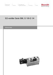
Electric Drivesand ControlsHydralicsLinear Motion andAssembly Technologies Pneumatics Service<strong>Profile</strong> <strong>cylinders</strong> <strong>Euromec</strong>, <strong>Series</strong><strong>168</strong>Technical data
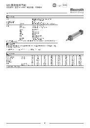
<strong>Profile</strong> <strong>cylinders</strong> <strong>Euromec</strong>, <strong>Series</strong> <strong>168</strong>Double-acting, magnetic piston, adjustable cushioning,25–100 mm dia.Part no.Piston Ø 25 32 40 50 63Piston rod thread M 10 x 1,25 M 10 x 1,25 M 12 x 1,25 M 16 x 1,5 M 16 x 1,5Connection port G1/8 G1/8 G 1/4 G 1/4 G 3/8Stroke25 <strong>168</strong>0202000 <strong>168</strong>0302000 <strong>168</strong>0402000 <strong>168</strong>0502000 <strong>168</strong>060200050 <strong>168</strong>0205000 <strong>168</strong>0305000 <strong>168</strong>0405000 <strong>168</strong>0505000 <strong>168</strong>060500080 <strong>168</strong>0208000 <strong>168</strong>0308000 <strong>168</strong>0408000 <strong>168</strong>0508000 <strong>168</strong>0608000100 <strong>168</strong>0210000 <strong>168</strong>0310000 <strong>168</strong>0410000 <strong>168</strong>0510000 <strong>168</strong>0610000125 <strong>168</strong>0212000 <strong>168</strong>0312000 <strong>168</strong>0412000 <strong>168</strong>0512000 <strong>168</strong>0612000160 <strong>168</strong>0216000 <strong>168</strong>0316000 <strong>168</strong>0416000 <strong>168</strong>0516000 <strong>168</strong>0616000200 <strong>168</strong>0220000 <strong>168</strong>0320000 <strong>168</strong>0420000 <strong>168</strong>0520000 <strong>168</strong>0620000250 <strong>168</strong>0225000 <strong>168</strong>0325000 <strong>168</strong>0425000 <strong>168</strong>0525000 <strong>168</strong>0625000320 – <strong>168</strong>0332000 <strong>168</strong>0432000 <strong>168</strong>0532000 <strong>168</strong>0632000400 – <strong>168</strong>0340000 <strong>168</strong>0440000 <strong>168</strong>0540000 <strong>168</strong>0640000500 – <strong>168</strong>0350000 <strong>168</strong>0450000 <strong>168</strong>0550000 <strong>168</strong>0650000Optional Stroke ²) <strong>168</strong>0200000 <strong>168</strong>0300000 <strong>168</strong>0400000 <strong>168</strong>0500000 <strong>168</strong>0600000Rec. max. stroke³) 1500 1500 1600 1600 1600Piston Ø 80 100Piston rod thread M 20 x 1,5 M 20 x 1,5Connection port G 3/8 G 1/2Stroke25 <strong>168</strong>0802010 <strong>168</strong>100202050 <strong>168</strong>0805010 <strong>168</strong>100502080 <strong>168</strong>0808010 <strong>168</strong>1008020100 <strong>168</strong>0810010 <strong>168</strong>1010020125 <strong>168</strong>0812010 <strong>168</strong>1012020160 <strong>168</strong>0816010 <strong>168</strong>1016020200 <strong>168</strong>0820010 <strong>168</strong>1020020250 <strong>168</strong>0825010 <strong>168</strong>1025020320 <strong>168</strong>0832010 <strong>168</strong>1032020400 <strong>168</strong>0840010 <strong>168</strong>1040020500 <strong>168</strong>0850010 <strong>168</strong>1050020Optional Stroke ²) <strong>168</strong>0800010 <strong>168</strong>1000020Rec. max. stroke³) 1700 1700²) When ordering optional stroke the length of the stroke must always be given in mm, for example <strong>168</strong>0300000, stroke 185 mm.³) Longer strokes on request.2
<strong>Profile</strong> <strong>cylinders</strong> <strong>Euromec</strong>, <strong>Series</strong> <strong>168</strong>Double-acting, magnetic piston, adjustable cushioning,25–100 mm dia.S* = StrokeTolerance 25–50 mm dia. = +2/-063–100 mm dia. = +2,5/-0PistonØB¹)e 11E P V AM BGmin.CC EA EE KK MMg 825 25³) 37 5 16 22 7,5 20 40 G 1/8 M 10x1,25 1232 30 45 5 15 22 16 28 49 G 1/8 M 10x1,25 1240 35 50 7 19 24 16 33 58 G 1/4 M12x1,25 1650 40 62 7 24 32 16 31 69 G 1/4 M16x1,5 2063 45 73 8 24 32 16 38 84 G 3/8 M16x1,5 2080 45 92 12 30 40 16 38 104 G 3/8 M 20x1,5 25100 55 109 10 35 40 16 42 126 G 1/2 M 20x1,5 25Piston NV1 NV2²) PL RT TG VA VD VF WH ZB ZDØ25 10 17 9 M 5 27 ±0,2 – 4 6 24 98 74 ±0,432 10 17 14 M6 32,5 ±0,2 3,5 4 6 26 120 94 ±0,440 13 19 15 M6 38 ±0,2 3,5 4 6,5 30 135 105 ±0,450 17 24 14 M8 46,5 ±0,2 4 4 8 37 143 106 ±0,463 17 24 18 M8 56,5 ±0,2 4 4 8 37 158 121±0,480 22 30 17 M 10 72 ±0,2 4 4 10 46 174 128 ±0,8100 22 30 21 M 10 89 ±0,2 4 4 10 51 189 138 ±0,8¹) There is no guide on the rear end cover of the 25 mm diameter cylinder.²) The cylinder is supplied fitted with a nut as per ISO 4035, DIN 439.³) This dimension does not correspond with 25 mm dia. <strong>cylinders</strong>, series 167. Other external dimensions are the same.4
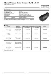
<strong>Profile</strong> <strong>cylinders</strong> <strong>Euromec</strong>, <strong>Series</strong> <strong>168</strong>Non-rotating piston rod, magnetic piston,adjustable cushioning, 32–63 mm dia.Technical Data for <strong>Euromec</strong> Splined (<strong>168</strong>-58)Standard (32–63 mm dia.) ISO 15552 (ISO 6431, VDMA 24562)CNOMO / NFE 49-003-1Working pressure, max.10 bar (145 psi)Ambient temperature range–20 °C to +70 °C (-13 °F to +158 °F)Medium Compressed air ISO 8573-1:2001, class 6-4-3 or lower*Materials Piston rod Hard chromium plated steelPiston rod dowel Steel, black oxidizedPiston rod bushing Steel with a PVDF + PTFE bearing surfaceCylinder body Anodized aluminumEnd coversAluminiumEnd cover screws Surface treated steelWiperPolyurethanePistonAluminumCushioning screw BrassSpline shaftSurface treated steelSpline sleeve PolyamideNutZinc plated steelSealsNitrile rubberApplication areaThis type is intended for applications where the piston rod movement must be secured againstrotation. Note that the piston rod must be held securely in it’s spanner flats when piston rodmountings are tightened so that the maximum permitted torque of the spline shaft is notexceeded.* Particle size ≤ 5 µm, dew point ≤ 3 °C, oil content ≤ 1 mg/m³Technical informationPiston diameter [mm] 32 40 50 63Maximum permitted instantaneous [Nm] 10 15 30 30(in.lbs) (88.51) (132.76) (265.52) (265.52)torque Mv continuous [Nm] 0,6 1 2 2(in.lbs) (5.31) (8.851) (17.70) (17.70)Max. turning play [°] ±1 ±1 ±1 ±1Spanner size X see fig. below [mm] 8 0/-0,2 10 0/-0,2 14 0/-0,2 14 0/-0,2Cylinder weight 0 mm stroke [kg] 0,45 0,76 1,10 1,70(lbs) (0.992) (1.68) (2.43) (3.75)add. per 100 mm [kg] 0,20 0,29 0,45 0,49(lbs) (0.441) (0.639) (0.992) (1.08)Part no.Piston Ø 32 40 50 63Piston rod thread M 10 x 1,25 M 12 x 1,25 M 16 x 1,5 M 16 x 1,5Connection port G1/8 G 1/4 G 1/4 G 3/8Stroke²)25 <strong>168</strong>5803020 <strong>168</strong>5804020 <strong>168</strong>5805020 <strong>168</strong>580602050 <strong>168</strong>5803050 <strong>168</strong>5804050 <strong>168</strong>5805050 <strong>168</strong>580605080 <strong>168</strong>5803080 <strong>168</strong>5804080 <strong>168</strong>5805080 <strong>168</strong>5806080100 <strong>168</strong>5803100 <strong>168</strong>5804100 <strong>168</strong>5805100 <strong>168</strong>5806100125 <strong>168</strong>5803120 <strong>168</strong>5804120 <strong>168</strong>5805120 <strong>168</strong>5806120160 <strong>168</strong>5803160 <strong>168</strong>5804160 <strong>168</strong>5805160 <strong>168</strong>5806160200 <strong>168</strong>5803200 <strong>168</strong>5804200 <strong>168</strong>5805200 <strong>168</strong>5806200250 – <strong>168</strong>5804250 <strong>168</strong>5805250 <strong>168</strong>5806250320 – – <strong>168</strong>5805320 <strong>168</strong>5806320400 – – <strong>168</strong>5805400 <strong>168</strong>5806400500 – – <strong>168</strong>5805500 <strong>168</strong>5806500Optional stroke¹) <strong>168</strong>5803000 <strong>168</strong>5804000 <strong>168</strong>5805000 <strong>168</strong>5806000Rec.max. stroke²) 500 750 990 990¹) When ordering optional stroke the length of the stroke must be given in mm, for example <strong>168</strong>5804000, stroke 185 mm.²) Longer strokes available on request.1
<strong>Profile</strong> <strong>cylinders</strong> <strong>Euromec</strong>, <strong>Series</strong> <strong>168</strong>Non-rotating piston rod, magnetic piston,adjustable cushioning, 32–63 mm dia.Cross section of piston rod threadX = See technical information above.2
<strong>Profile</strong> <strong>cylinders</strong> <strong>Euromec</strong>, <strong>Series</strong> <strong>168</strong>Low pressure hydraulics, magnetic piston, 25–100 mm dia.Technical Data for <strong>Euromec</strong> (<strong>168</strong>-52)Standard (32–100 mm dia.) ISO 15552 (ISO 6431, VDMA 24562)CNOMO / NFE 49-003-1Working pressure, max.10 bar (145 psi)Ambient temperature range–20 °C to +70 °C (-13 °F to +158 °F)MediumFluid, see technical information belowDimensions, see standard <strong>cylinders</strong>Materials Piston rod Stainless steel (BS 303 S 31)Piston rod bushing Steel with a PVDF + PTFE bearing surfaceCylinder body Anodized aluminumEnd coversAluminiumEnd cover screws Surface treated steelWiperPolyurethanePiston25–63 mm dia. polyamide,80–100 mm dia. AluminumCushioning screw BrassSealsNitrile rubberNutsZinc plated steelApplication areaThis cylinder type is used when an even and/or very slow piston movement is required even ifthe load varies. A needle valve should be used between the reservoirs in the connectionexample.Technical Information (for further information see section 15)SymbolConnection exampleThe recommended pressure medium for this type is hydraulic fluid.Bearing in mind pressure losses, the viscosity should not exceed 20 mm²/s (2.9° E) atoperating temperature.A suitable hydraulic fluid is oil of the ATF-DEXRON type (Part no. 8982000010) or oilswith an aniline point of 93 °C ±5. (199 °F ±41)For other pressure mediums, please contact your nearest <strong>Bosch</strong> <strong>Rexroth</strong> office.Part no.SymbolOrdering exampleWhen ordering please state the series/piston diameter/stroke.Example: <strong>Euromec</strong> -52/32/300.Longer strokes than rec. max stroke (see standard) are available on request.1
<strong>Profile</strong> <strong>cylinders</strong> <strong>Euromec</strong>, <strong>Series</strong> <strong>168</strong>High operating temperatures,
<strong>Profile</strong> <strong>cylinders</strong> <strong>Euromec</strong>, <strong>Series</strong> <strong>168</strong>With position holder, magnetic piston,adjustable cushioning, 32–100 mm dia.Technical Data for <strong>Euromec</strong> (<strong>168</strong>-54)Type, piston rod lockNormally closed (in brake position)StandardMounting holes for position holder and <strong>Euromec</strong>et <strong>Euromec</strong>to VDMA 24562 and CNOMO/NFE 49-003Working pressure max. 10 bar (145 psi)Release pressure min. 4 bar (58 psi) (position holder)Ambient temperature range-15 °C to +70 °C (+5 °F to +158 °F)Medium Compressed air ISO 8573-1:2001, class 6-4-3 or lower*Materials Housing Anodized aluminumPiston rod Stainless steel (BS 303 S 31)Piston rod bushing Steel with a PVDF + PTFE bearing surfaceCylinder body Anodized aluminumEnd coversAluminiumEnd cover screws Surface treated steelWiperPolyurethanePistonØ 32–63 polyamide, Ø 80-100 aluminumCushioning screws BrassMounting screws Zinc plated steelSealsNitrile rubberNutsZinc plated steelApplication areaThe piston rod lock is used to secure the piston rod in any chosen position along the stroke.As a machine safeguard: locks securely when air is lost or in an emergency stop. Must not beused as a personnel safeguard.* Particle size ≤ 5 µm, dew point ≤ 3 °C, oil content ≤ 1 mg/m³Technical informationPiston diameter [mm] 32 40 50 63 80 100Min. holding force at 0 bar for vented holder [N] 760 1200 1900 3000 5000 8000(lbf) (171) (270) (427) (674) (1120) (1800)Cylinder weight 0 mm stroke [kg] 1,25 1,76 2,9 4,5 8 13,2(lbs) (2.76) (3.88) (6.39) (9.92) (17.6) (29.1)add. per 100 mm [kg] 0,20 0,29 0,45 0,49 0,78 1,00(lbs) (0.441) (0.639) (0.992) (1.08) (1.72) (2.2)Piston Ø Ø32 mm Ø40 mm Ø50 mm Ø63 mm Ø80 mm Ø100 mmPiston rod thread M 10x1,25 M 12x1,25 M 16x1,5 M 16x1,5 M 20x1,5 M 20x1,5Connection port G1/8 G1/8 G 1/4 G 1/4 G 3/8 G 3/8Optional stroke¹) <strong>168</strong>5403000 <strong>168</strong>5404000 <strong>168</strong>5405000 <strong>168</strong>5406000 <strong>168</strong>5408000 <strong>168</strong>5410000Part no.SymbolOrdering exampleWhen ordering please state the series/piston diameter/stroke.Example: <strong>Euromec</strong> -54/32/300.Longer strokes than rec. max stroke (see standard) are available on request1
<strong>Profile</strong> <strong>cylinders</strong> <strong>Euromec</strong>, <strong>Series</strong> <strong>168</strong>With position holder, magnetic piston,adjustable cushioning, 32–100 mm dia.S* = StrokePistonØA B C Ee 11F L20 BG** EE RT TG WH ZD Tol.stroke32 125 19 9 30 48 44 16 G 1/8 M 6 32,5 30 219 +2/–040 125 21 9 35 53 44 16 G 1/8 M 6 38 32 230 +2/–050 145 28 9 40 63 49 16 G 1/8 M8 46,5 41 251 +2/–063 165 28 10 45 75 52 16 G 1/8 M8 56,5 41 286 +2,5/–080 185 34 11 45 98 61,5 17 G 1/8 M 10 72 50 313 +2,5/–0100 220 37 13 55 118 68 17 G 1/8 M 10 89 53 358 +2,5/–0** Thread depth.For other dimensions, see <strong>Euromec</strong> standard.Accessories and mountings (to be ordered separetely)Spare parts kit, see separate documentation.Subbases for control valve and wiper for the rear of the position holder for use without a cylinderInductive sensor M12x1 with a connecting distance of 2 mm can be mounted in prepared holes.The sensor is activated when the disconnection pressure is 0 bar, i.e. the position holder is activated.2
<strong>Profile</strong> <strong>cylinders</strong> <strong>Euromec</strong>, <strong>Series</strong> <strong>168</strong>Corrosive environments, magnetic piston,adjustable cushioning, 25–100 mm dia.Technical Data for <strong>Euromec</strong> Clean (<strong>168</strong>-59)Standard (32–100 mm dia.) ISO 15552 (ISO 6431, VDMA 24562)CNOMO / NFE 49-003-1Working pressure, max.10 bar (145 psi)Ambient temperature range–20 °C to +70 °C (-13 °F to +158 °F)Medium Compressed air ISO 8573-1:2001, class 6-4-3 or lower*Dimensions, see standard <strong>cylinders</strong>Materials Piston rod Stainless steel (BS 303 S 31)Piston rod bushing Steel with a PVDF + PTFE bearing surfaceCylinder body Anodized aluminumEnd coversAnodized aluminumEnd cover screws Stainless steel (BS 303 S 31)WiperPolyurethanePiston25–63 mm dia. polyamide,80-100 mm dia. AluminumCushioning screw Stainless steel (BS 303 S 31)SealsNitrile rubberNut Stainless steel (BS 303 S31)Application areaThe strengthened corrosion protection makes this type of cylinder suitable for the food industry,animal food production, laundries, heating, water and sanitation plants, etc.In order to prevent dirt collecting in the mounting holes, hygienic plugs (8 pcs) in thermoplasticrubber can ordered for these, available on request.* Particle size ≤ 5 µm, dew point ≤ 3 °C, oil content ≤ 1 mg/m³Part no.SymbolOrdering exampleWhen ordering please state the series/piston diameter/stroke.Example: <strong>Euromec</strong> -59/32/300.Longer strokes than rec max. stroke (see standard) are available on request.1
<strong>Profile</strong> <strong>cylinders</strong> <strong>Euromec</strong>, <strong>Series</strong> <strong>168</strong>AccessoriesFlange front or rearISO MF 1/MF 2, VDMA, NFES* = StrokePistonØPart no. E RJS 14WFBH 13MFTFJS 14UF ZF Weight[kg] (lbs)25 3682002000 40 26 14 ±1,6 7 10 52 66 108 ±1,3 0,2 (0.44)32 5230006012 50 32 16 ±1,6 7 10 64 80 130 ±1,3 0,3 (0.66)40 5231006012 55 36 20 ±1,6 9 10 72 90 145 ±1,3 0,4 (0.88)50 5232006012 65 45 25 ±1,6 9 12 90 110 155 ±1,3 0,5 (1.1)63 5233006012 75 50 25 ±2 9 12 100 125 170 ±1,6 1,0 (2.2)80 5234006012 100 63 30 ±2 12 16 126 154 190 ±1,6 1,7 (3.75)100 5235006012 120 75 35 ±2 14 16 150 180 205 ±1,6 2,3 (5.07)Materials: Zinc plated steel.Supplied complete with mounting screws for attachment to the cylinder.1
Angle bracketsISO MS 1, VDMA, NFES* = StrokePistonØPart no. E ABH 14AHJS 15A0 AT AU±0,2SATRJS 14XAWeight[kg] (lbs)25 3682202000 40 7 25 8 4 22 118 ±1,0 26 120 ±1,3 0,1 (0.22)32 5230000502 48 7 32 11 5 24 142 ±1,25 32 144 ±1,3 0,1 (0.22)40 5231000502 53 9 36 12 5 28 161 ±1,25 36 163 ±1,3 0,2 (0.44)50 5232000502 63 9 45 13 5 32 170 ±1,25 45 175 ±1,3 0,3 (0.66)63 5233000502 73 9 50 13 5 32 185 ±1,6 50 190 ±1,6 0,3 (0.66)80 5234000502 98 12 63 19 6 41 210 ±1,6 63 215 ±1,6 0,6 (1.32)100 5235000502 115 14,5 71 19 6 41 220 ±1,6 75 230 ±1,6 0,7 (1.54)Materials: Zinc plated steel.Supplied complete with mounting screws for attachment to the cylinder. The mountings are delivered in pairs.1
Central male trunnionISO MT4, VDMA, NFEPiston Ø Part no. TT TDe 9TLh 14TMh 14TU UW Weight[kg] (lbs)25 3682802000 15 10 11 50 72 65 0,2 (0.44)32 3682803000 24 12 12 50 74 65 0,3 (0.66)40 3682804000 24 16 16 63 95 75 0,5 (1.1)50 3682805000 27 16 16 75 107 92 0,8 (1.76)63 3682806000 36 20 20 90 130 105 1,3 (2.87)80 3682808000 36 20 20 110 150 128 1,7 (3.75)100 3682810000 48 25 25 132 182 145 3,2 (7.05)Materials: Nitro-carburized steel.Moveable, lubrication free, central male trunnion with axle pivots (the mounting can be assembled without dismantling the cylinder).1
Pivoted mountingISO MT5, MT6S* = StrokePiston Ø Part no. EmaxTD TL TM TT XH XL Weighte 9 [kg] (lbs)25 3683802000 40 10 11 50 14 17 105 0,2 (0.44)32 5230816902 50 12 12 50 16 18 128 0,2 (0.44)40 5231816902 55 16 16 63 20 20 145 0,4 (0.88)50 5232816902 65 16 16 75 24 25 155 0,5 (1.1)63 5233816902 75 20 20 90 24 25 170 1,0 (2.2)80 5234816902 100 20 20 110 28 32 188 1,7 (3.75)100 5235816902 123 25 25 132 38 32 208 3 (6.61)Materials: Galvanized steel.This mounting is supplied complete with mounting screws for attachment to the cylinder.In contrast to the central male trunnion, the pivoted mounting enables a sensor to be mounted for sensing the end position of the cylinder.This mounting can be mounted with dowels on the same side as, or 90° to, the connection port.Note: When the mounting is mounted with dowels on the same side as the connection port, consideration must be given to the space required forthe bearing brackets.1
Bearing bracketsPiston Ø Part no. A B B1 C D Ø d1 d2 F f H1 H2 NH 732 5230603402 32 15 46 7,5 3 12 6,6 11 1,2 30 15 6,840 5232603402 36 18 55 9 3 16 9 15 1,6 36 18 950 5232603402 36 18 55 9 3 16 9 15 1,6 36 18 963 5234603402 42 20 65 10 3 20 11 18 1,6 40 20 1180 5234603402 42 20 65 10 3 20 11 18 1,6 40 20 11100 5236603402 50 25 75 12,5 3,5 25 14 20 2 50 25 13Supplied in pairs.Material: Galvanized steel with sintered bushing.1
Rear clevisISO, MP2, VDMA, NFES* = StrokePistonØPart no. E L CBH 14CDH 9FL±0,2MRUBh 14XD±1,25Weight[kg] (lbs)32 1827001289 48 14 26 10 22 11 45 142 0,1 (0.22)40 5231003402 53 16 28 12 25 13 52 160 0,2 (0.44)50 5232003402 63 16 32 12 27 13 60 170 0,3 (0.66)63 5233003402 73 20 40 16 32 17 70 190 0,4 (0.88)80 5234003402 98 22 50 16 36 17 90 210 0,6 (1.32)100 5235003402 115 27 60 20 41 21 110 230 0,9 (1.98)Material: Aluminum, with screws, without the pivot pin, with PTFE bushing.The mounting together with "Rear eye with PTFE bushing" (MP4) + pivot pin (523 X00 009) form a complete pivot mounting.Piston Ø Part no. E L CBH 14CDe 8FL±0,2MRUBh 14VB XD Weight[kg] (lbs)25 3682902590 40 14 18 10 20 9 36 41 118 ±1,3 0,1 (0.22)32 3682903590 47 12 26 10 22 11 45 50 142 ±1,3 0,1 (0.22)40 3682904590 54 15 28 12 25 13 52 57 160 ±1,3 0,2 (0.44)50 3682905590 65 15 32 12 27 13 60 65 170 ±0,3 0,2 (0.44)63 3682906590 75 20 40 16 32 17 70 76 190 ±1,6 0,4 (0.88)80 3682908590 94 20 50 16 36 17 90 96 210 ±1,6 0,5 (1.1)100 3682910590 112 25 60 20 41 21 110 117 230 ±1,6 0,9 (1.98)Material: Anodized aluminum. The mounting is delivered with a pivot pin, circlips and mounting screws in stainless steel.This mounting together with "Rear eye with PTFE bushing" (MP4) alternative "Rear eye with rubber bushing" form a complete pivot mounting.1
Rear end cover clevisISO MP0, VDMA, NFES* = StrokePistonØPart no. E CD CBH 14UBd 12FL±0,2L MR XD Weight[kg] (lbs)32 5230003432 48 10 14 34 22 11,5 11 142 0,1 (0.22)40 5231003432 53 12 16 40 25 12 13 160 0,2 (0.44)50 5232003432 63 16 21 45 27 14 18 170 0,3 (0.66)63 5233003432 73 16 21 51 32 14 18 190 0,4 (0.88)80 5234003432 98 20 25 65 36 16 22 210 0,6 (1.32)100 5235003432 115 20 25 75 41 16 22 230 0,9 (1.98)Material: Grey cast iron.1
Rear eye with rubber bushingISO, NFEPiston Ø Part no. E L CDH 9EW FL NR¹) XD Weight[kg] (lbs)25 3683202000 40 14,5 10 17,5 20 12 118 ±1,3 0,1 (0.22)32 3683203000 46 16,5 10 25,5 22 14 142 ±1,3 0,1 (0.22)40 3683204000 55 17,5 12 27,0 25 19 160 ±1,3 0,1 (0.22)50 3683205000 62 18,5 12 31,0 27 19,5 170 ±1,3 0,2 (0.44)63 3683206000 80 21,5 16 39,5 32 26 190 ±1,6 0,3 (0.66)80 3683208000 94 24,5 16 49,5 36 27 210 ±1,6 0,4 (0.88)100 3683210000 114 26,5 20 59,5 41 29 230 ±1,6 0,7 (1.54)Materials: Aluminum with a bronze bushing encapsulated in vulcanized rubber, lubrication-free.This mounting is supplied complete with mounting screws for attachment to the cylinder.¹) This dimension exceeds the ISO standard.1
Rear eye with PTFE bushing (MP4)ISO, VDMA, NFES* = StrokePistonØPart no. E L CDH 9EWFL±0,2MR XD Weight[kg] (lbs)32 1827001283 48 14 10 26 –0,2/–0,6 22 11 142 ±1,3 0,1 (0.22)40 1827001284 53 16 12 28 –0,2/–0,6 25 13 160 ±1,3 0,2 (0.44)50 1827001285 63 16 12 32 –0,2/–0,6 27 13 170 ±1,3 0,2 (0.44)63 1827020086 73 20 16 40 –0,2/–0,6 32 17 190 ±1,6 0,4 (0.88)80 1827001287 98 22 16 50 –0,2/–0,6 36 17 210 ±1,6 0,6 (1.32)100 1827001288 115 27 20 60 –0,2/–0,6 41 21 230 ±1,6 1,0 (2.2)Material: Aluminum with PTFE bushing.The mounting is supplied complete with mounting screws for attachment to the cylinder.1
Rear eye with ball jointS* = StrokePiston Ø Part no. E CDH 7EX FL L MS XD Weight[kg] (lbs)25 3683602000 40 10 14 20 14 14 118 ±1,3 0,1 (0.22)32 3683603000 46 10 14 22 16 17 142 ±1,3 0,1 (0.22)40 3683604000 55 12 16 25 17 20 160 ±1,3 0,2 (0.44)50 3683605000 62 12 16 27 18 22 170 ±1,3 0,2 (0.44)63 3683606000 80 16 21 32 21 25 190 ±1,6 0,4 (0.88)80 3683608000 94 16 21 36 24 30 210 ±1,6 0,5 (1.1)100 3683610000 114 20 25 41 26 32 230 ±1,6 0,9 (1.98)Materials: Aluminum with a steel ball joint, lubrication-free.This mounting is supplied complete with mounting screws for attachment to the cylinder.1
Foot mountingPiston Ø Part no. A B C D E F G H Stroke min. Weight[kg] (lbs)25 3682302001 35 70 43,0 6,5 20 28,5 47,3 – 5 0,115 (0.254)32 3682303001 40 80 36,5 6,5 31 28,0 50,5 32,5 5 0,125 (0.276)40 3682304001 40 90 45,1 6,5 31 35,1 60,1 32,5 5 0,160 (0.353)50 3682305001 40 100 48,0 6,5 31 39,9 70,9 32,5 0 0,190 (0.419)Material: Black-anodized aluminum.The mounting can be placed anywhere along the length of the cylinder.It is supplied in units with mounting screws for attachment to the cylinder.Note: For precision mounting and long strokes, two mountings are recommended.1
Pivot pin with anti-rotation device for "Bearing block with ball and foot" and "rear eye"PistonØPart no. A B C D3–0,1D4H 12EKh 9L10/+0,2L3 L2 L4–0,432 5230000082 18 22 10 10 3 10 32,5 41 4,5 1440 5231000082 22 26 12 12 4 12 38,0 48 5 1650 5232000082 28 34,5 16 16 4 16 43,0 54 6 2063 5233000082 28 34,5 16 16 4 16 49,0 60 6 2080 5234000082 28 34,5 16 16 4 20 63,0 74 6 24100 5235000082 28 34,5 16 16 4 20 73,0 84 6 24Material: Hardened steel.1
Bearing block with footPistonØPart no.CKh 9EM–0,2/–0,6G1G2JS 14G3 H6 K1JS 14K2max.R1max.CAJs 5S5L3max.Weight[kg](lbs)32 5230003422 10 26 21 18 31 8 38 51 10 32 6,6 10 0,17(0.375)40 5231003422 12 28 24 22 35 10 41 54 11 36 6,6 12 0,21(0.463)50 5232003422 12 32 33 30 45 12 50 65 13 45 9,0 16 0,44(0.97)63 5233003422 16 40 37 35 50 12 52 67 15 50 9,0 16 0,54(1.19)80 5234003422 16 50 47 40 60 14 66 86 15 63 11,0 20 0,96(2.12)100 5235003422 20 60 55 50 70 15 76 96 19 71 11,0 20 1,37(3.02)Material: GGG 40.1
Bearing block with ball joint and footPistonØPart no.CHJS 15CNH 7EN–0,1ER EU G1JS 14G2JS 14G3 H6 H1 K1JS 14K2S5H 13Weight[kg](lbs)32 5230003442 32 10 14 16 10,5 21 18 31 10 16 38 51 6,6 0,19(0.42)40 5231003442 36 12 16 18 12 24 22 35 10 16 41 54 6,6 0,25(0.55)50 5232003442 45 16 21 21 15 33 30 45 12 23 50 65 9,0 0,46(1.01)63 5233003442 50 16 21 23 15 37 35 50 12 23 52 67 9,0 0,75(1.65)80 5234003442 63 20 25 28 18 47 40 60 14 32 66 86 11,0 1,04(2.29)100 5235003442 71 20 25 30 18 55 50 70 15 33 76 96 11,0 1,41(3.11)Material: Grey cast iron, with steel ball.1
Pivot pin with locking rings for "Bearing block with foot" and "rear eye"Piston Ø Part no. Part no. A Dmax.EKd 10ELWeight[kg] (lbs)32 5230000092 5230800092 19,0 56 10 46 +1 0,03 (0.066)40 5231000092 5231800092 21,0 63 12 53 +1 0,05 (0.11)50 5232000092 5232800092 21,0 73 12 61 +1 0,06 (0.132)63 5233000092 5233800092 27,6 85 16 71 +1 0,12 (0.265)80 5234000092 5234800092 27,6 105 16 91 +1 0,16 (0.353)100 5235000092 5235800092 40,0 129 20 111 +1 0,27 (0.595)Materials: BS 303 S31 Hardened steel1
Bearing brackets aluminum, lubrication-free* The maximum pendulum movement for <strong>cylinders</strong> with rear eye 368-36 or 366-36 is ±45 °C (±113 °F)CRH 8Part no. EA FA FE FK±0,1FN HB NH TH UL Weight[kg] (lbs)10 3671202000 16 10 – 21 29 5,5 10 27 37 0,08 (0.176)12 3671203000 19 11 17 22 32 6,6 11 44 55 0,06 (0.132)16 3671204000 28 16 25 35 49 9,0 16 65 82 0,17 (0.375)20 3671206000 38 19 29 40 59 9,0 19 80 99 0,28 (0.617)Supplied in pairs.Materials: Aluminum with steel bushings provided with a plastic surface coating, intended for normal loading cases.For mounting together with ball eye rod end or, alternatively, central male trunnion, pivoted mounting or rear eye (see the cylinder mounting forthe respective cylinder).For ball eye rod end and rear eye a pivot pin kit is also required.1
Steel bearing brackets* The maximum pendulum movement for <strong>cylinders</strong> with rear eye 368-36 or 366-36 is ±45 °C (±113 °F)CRH 8Part no. EA FA FE FK±0,1FN HB NH TH UL Weight[kg] (lbs)10 3661202000 16 10 – 21 29 5,5 10 27 37 0,08 (0.176)12 3661203000 19 11 17 22 32 6,6 11 44 55 0,16 (0.353)16 3661204000 28 16 25 35 49 9,0 16 65 82 0,50 (1.1)20 3661206000 38 19 29 40 59 9,0 19 80 99 0,80 (1.76)25 3661210000 46 22 34 48 71 11,0 22 96 118 1,30 (2.87)Supplied in pairs.Material: Zinc plated steel.Intended for more difficult loading cases and in conjunction with high temperature <strong>cylinders</strong>.For mounting together with "ball eye rod end" or, alternatively, "central male trunnion", "pivoted mounting" or "rear eye" (see the cylinder mountingfor the respective cylinder).For ball eye rod end and rear eye a pivot pin kit is also required.1
Pivot pin kitPart no. CN e8 AN AP Weight [kg] (lbs)3681302000 10 24,2 39 0,03 (0.066)3681304000 12 27,5 44 0,05 (0.11)3681305000 16 37,5 59 0,11 (0.243)3681308000 20 44,5 70 0,18 (0.397)Material: Hardened steel.Can be combined with "ball eye rod end", "Rear eye with ball point" (368-36) and brackets.The axle is supplied with circlips.1
Extra nut ISO 4035Thread KKPart no.Zinc plated steelPart no.Stainless steel(BS 303 S31)KT KU Weight [kg](lbs)M10x1,25 3670302000 3590302000 17 5 0,008 (0.018)M12x1,25 3670304000 3590304000 19 6 0,014 (0.031)M16x1,5 3670305000 3590305000 24 8 0,024 (0.053)M20x1,5 3670308000 3590308000 30 10 0,045 (0.099)1
Rod clevis ISO 8140Thread KK Part no. D1 CK CM LE ER CE L1 BL CL Weight[kg] (lbs)M10x1,25 1822122024 18 10 10 20 12 40 15 26 20 0,1 (0.22)M12x1,25 1822122025 20 12 12 24 14 48 18 31 24 0,2 (0.44)M16x1,5 1822122005 26 16 16 32 19 64 24 39 32 0,4 (0.88)M20x1,5 1822122004 34 20 20 40 20 80 30 49 40 0,7 (1.54)Material: Zinc plated steel.1
Clevis in stainless steel ISO 8140 (M 10-M 20)Thread KK Part no. BL CE CKe 8CL CMB 12ER LE Weight[kg] (lbs)M10x1,25 3590502000 25 40 10 20 10 12 20 0,1 (0.22)M12x1,25 3590504000 30 48 12 24 12 14 24 0,2 (0.44)M16x1,5 3590505000 38 64 16 32 16 19 32 0,4 (0.88)M20x1,5 3590508000 47 80 20 40 20 25 40 0,7 (1.54)Material: Stainless steel (BS 303 S31).1
Mounting plateD E F H Weight [kg] (lbs)Thread KK Part no. A B Ch 9M10x1,25 3670803000 9 M6 29 19,0 30 5 24 0,05 (0.11)M12x1,25 3670804000 12 M6 34 22,5 36 5 26 0,08 (0.176)M16x1,5 3670805000 12 M8 44 30,0 46 5 32 0,14 (0.309)Material: Anodized aluminum.The mounting is delivered complete with screws for locking on the piston rod. Intended for mounting "tools" on the piston rod.1
Ball eye rod end ISO 8139Thread KK Part no. AV CE CNH7EN0/–0,1EUERmax.F H LF α° Weight[kg] (lbs)M10x1,25 1822124003 20 43 10 14 10,5 14 12,9 17 14 26 0,08 (0.176)M12x1,25 1822124004 22 50 12 16 12,0 16 15,4 19 16 26 0,10 (0.22)M16x1,5 1822124205 28 64 16 21 15,0 21 19,3 22 21 30 0,30 (0.661)M20x1,5 1822124006 33 77 20 25 18,0 25 24,3 32 25 30 0,40 (0.882)Material: Zinc plated steel, with hardened swivel bearing (maintenance free).1
Flexible coupling* Angular displacement of center line.** Radial displacement of center line.Thread KK Part no. B 1 D 1 D 2 D 3 Fmin.L±2L 2L3±1SW1SW2SW3SW4RV Weight[kg](lbs)M10x1,25 1826409002 6 21,5 34 14 23 71 20 7,5 19 12 17 30 0,7 0,17(0.375)M12x1,25 1826409003 7 21,5 34 14 24 75 24 13,0 19 12 19 30 0,7 0,23(0.507)M16x1,5 1826409004 8 33,5 47 22 32 103 32 9,0 30 19 24 41 1,0 0,62(1.37)M20x1,5 1826409005 10 33,5 47 22 41 119 40 19,0 30 19 30 41 1,0 0,72(1.59)Material: Galvanized steel.1
<strong>Profile</strong> <strong>cylinders</strong>, series PRA, PRBAccessoriesFlexible coupling with mounting plate (B)Axial play: 0,4 ... 0,8 mm (Ø32–125); 0,4 ... 0,95 mm (160 / 200)Radial play: 2 ...4 mm (Ø32–125); 3 mm (160 / 200)Material: Steel, galvanizedPistonØPart no. KK a1 a2 d1H11d6H13d7H13e1H13e2 h1 t2 H SW Weight[kg] (lbs)32 1827001629 M10x1,25 60 37 20 6,6 11 36±0,15 23±0,15 15 7 24 17 0,300 (0.66)40 1827001630 M12x1,25 60 56 25 9 15 42±0,2 38±0,2 20 9 30 19 0,400 (0.88)50 1827001631 M16x1,5 80 80 30 11 18 58±0,2 58±0,2 20 11 32 24 0,900 (1.98)63 1827001631 M16x1,5 80 80 30 11 18 58±0,2 58±0,2 20 11 32 24 0,900 (1.98)80 1827001632 M20x1,5 90 90 40 14 20 65±0,3 65±0,3 20 13 35 36 1,150 (2.54)100 1827001632 M20x1,5 90 90 40 14 20 65±0,3 65±0,3 20 13 35 36 1,150 (2.54)125 1827001633 M27x2 90 90 40 14 20 65±0,3 65±0,3 20 13 35 36 1,100 (2.43)160 1827001634 M36x2 125 125 60 18 26 90±0,3 90±0,3 30 17 55 50 3,400 (7.5)200 1827001634 M36x2 125 125 60 18 26 90±0,3 90±0,3 30 17 55 50 3,400 (7.5)1
<strong>Profile</strong> <strong>cylinders</strong> <strong>Euromec</strong>, <strong>Series</strong> <strong>168</strong>Linear control unitsLinear control unit, H-shapeTypeStandardAmbient temperature rangeH-shapeLinear control units suitable for <strong>cylinders</strong>as per ISO 6432, VDMA 24562 andCNOMO / NFE 49-003-20 °C to +80 °C (-4 °F to +176 °F)Materials Bearing housing Anodized aluminumCarrying plate Anodized aluminumControl rods for Stainless steel, smooth-rolledplain bearingFlexible coupling in the Stainless steel, smooth-rolledcarrying platePlain bearing Sintered bronzeBall bearingSteelScrewsGalvanized steelApplication areaGuide unit reduces bending of the piston rod when positioning high loadsHigh precision due to long guideHigh useful load due to solid guide rodsTechnical informationPiston Ø [mm] 32 40 50 63 80 100Weight 0 mm stroke [kg] 1,300 2,300 3,700 4,700 8,800 11,100(lbs) (2.866) (5.071) (8.157) (10.362) (19.401) (24.471)H-shape, ball bearing add. per 100 mm [kg] 0,090 0,160 0,250 0,250 0,390 0,390(lbs) (0.198) (0.353) (0.551) (0.551) (0.860) (0.860)Weight 0 mm stroke [kg] 1,300 2,300 3,700 4,700 8,800 11,100(lbs) (2.866) (5.071) (8.157) (10.362) (19.401) (24.471)H-shape, plain bearing add. per 100 mm [kg] 0,090 0,160 0,250 0,250 0,390 0,390(lbs) (0.198) (0.353) (0.551) (0.551) (0.860) (0.860)Part no. H-shape, sinter friction bearing (L1)For piston dia. 32 40 50 63 80 100Stroke50 0821401220 0821401230 0821401240 0821401280 - -100 0821401221 0821401231 0821401241 0821401281 0821401260 0821401270160 0821401222 0821401232 0821401242 0821401285 - -200 0821401223 0821401233 0821401243 0821401282 0821401261 0821401271250 0821401224 0821401234 0821401244 0821401286 - -320 0821401225 0821401235 0821401245 0821401283 0821401262 0821401272400 0821401226 0821401236 0821401246 0821401287 - -500 0821401227 0821401237 0821401247 0821401284 0821401263 0821401273600 0821401228 0821401238 0821401249 0821401288 0821401264 0821401274800 0821401229 0821401239 0821401474 0821401289 0821401265 08214012751000 0821401470 0821401472 0821401475 0821401290 0821401266 08214012761200 0821401471 0821401473 0821401476 0821401291 0821401267 0821401277Rec. max. stroke 1200 1200 1200 1200 1200 1200Spare parts kit (to be ordered separately)Piston dia.Order no.32 182700941540 182700941650 182700953063 182700953080 1827009535100 18270095351
<strong>Profile</strong> <strong>cylinders</strong> <strong>Euromec</strong>, <strong>Series</strong> <strong>168</strong>Linear control unitsPart no. H-shape, linear ball bearings (L5)For piston dia. 32 40 50 63 80 100Stroke50 0821401320 0821401330 0821401340 0821401380 – –100 0821401321 0821401331 0821401341 0821401381 0821401360 0821401370200 0821401322 0821401332 0821401342 0821401382 0821401361 0821401371320 0821401323 0821401333 0821401343 0821401383 0821401362 0821401372500 0821401324 0821401334 0821401344 0821401384 0821401363 0821401373600 0821401325 0821401335 0821401345 0821401385 0821401364 0821401374800 0821401326 0821401336 0821401346 0821401386 0821401365 08214013751000 0821401327 0821401337 0821401347 0821401387 0821401366 08214013761200 0821401328 0821401338 0821401348 0821401388 0821401367 0821401377Rec. max. stroke 1200 1200 1200 1200 1200 1200Spare parts kit (to be ordered separately)Piston dia.Part no.32 182700952640 182700952750 182700952863 182700952880 1827009529100 1827009529A2
<strong>Profile</strong> <strong>cylinders</strong> <strong>Euromec</strong>, <strong>Series</strong> <strong>168</strong>Linear control unitsH = StrokeRelubricate ball bearings after 5000 km (lubricating grease KP2K DIN 51825), order no. 1829991099Lubricate more often in dusty conditionsPistondia.A1 A2 A3 A4 A5 B C G1 G2 G3 G4 L1 L2 L3 L4 L5 L6 L7 L8 L9 L10 L11 L12*1,232 78 32,5 61 81 50 12 74 M6 6,6 11 6,5 90 45 97 177 125 6 17 12 94 17 4,3 64 +540 84 38 69 99 54 16 87 M6 6,6 11 6,5 110 54 115 192 140 7 22 12 105 21 11 74 +550 100 46,5 85 119 72 20 104 M8 9 15 9 130 63 137 205 150 8 26 15 106 26 18,8 89 +1063 105 56,5 100 132 82 20 119 M8 9 15 9 145 80 152 237 182 8 26 15 121 26 15,3 89 +1080 130 72 130 166 106 25 148 M10 11 18 11 180 100 189 280 215 9 32 20 128 34 21 110 +10100 150 89 150 190 131 25 172 M10 11 18 11 200 120 213 280 220 9 32 20 138 39 24,5 115 +10Pistondia.L13 L14 L15*2L17L18M8L19*2L19A*3*2L20 L21 L22 SW 1 SW 2 R1R2H7E+1F+1ØG+0,5ØH SW T32 50 76 37 50,2 +0,4 30 14 –2 SW30 6 16,2 13 17 6 5 7 6 5 5 1440 58 81 37 58,2 +0,4 35 8 –9 45 14 19 15 19 6 6 8 7 6 6 1450 70 79 37 70,2 +0,4 40 36 +18 54 14 23,2 22 24 6 6 8 7 6 6 1663 85 111 37 85,2 +0,4 45 21 +2 54 14 28,2 22 24 6 6 8 7 6 6 <strong>168</strong>0 105 128 42 105,4 +0,6 45 34 +14 60 14 36 27 30 6 7 9 9,4 8 8 20100 130 128 37 130,4 +0,6 55 19 –2 60 14 44,5 27 30 6 7 9 9,4 8 8 20These values apply for linear ball bearings as well as for sinter-friction bearings. For differing values, see below.*1 Change the adjustment range of the flexible coupling accordingly (see L15 and L19)*2 For retracted cylinder**3 Cylinders without signal3
<strong>Profile</strong> <strong>cylinders</strong> <strong>Euromec</strong>, <strong>Series</strong> <strong>168</strong>Linear control unitsPiston dia.L15*2These values apply 32 37 14 –2 177for sinter-friction 40 37 8 –9 192bearings 50 37 4 –14 20563 37 21 +2 23780 42 34 +14 280100 37 19 –2 280L19*2L19A*3*2L44
<strong>Profile</strong> <strong>cylinders</strong> <strong>Euromec</strong>, <strong>Series</strong> <strong>168</strong>Linear control unitsUseful loadUseful load for linear control units with sinter friction bearingsF = Useful loadZ = Bearing-outUseful loadService life 2 x 10 6 mUseful load for linear control units with linear ball bearingsF = Useful loadZ = Bearing-out5
<strong>Profile</strong> <strong>cylinders</strong> <strong>Euromec</strong>, <strong>Series</strong> <strong>168</strong>Linear control unitsReduction of useful load on short strokesk = adjustment factor: normal = 1; on impact: 2The nominal load data determined for short-stroke movements from the diagram have to be multiplied with the adjustment factor k.These short-stroke adjustments are already included in the load diagram for a bearing-out of more than 60 mm.Service life 5 x 10 6 mF permit = F x 0,5BendingF = Useful load (at the load center)SF = BendingZ = Bearing-out6
<strong>Profile</strong> <strong>cylinders</strong> <strong>Euromec</strong>, <strong>Series</strong> <strong>168</strong>Linear control unitsBending due to own loadBending due to 10 N load7
Sensor mounting for Sensors 275Piston ØPart no.25–100 2752111000Material: Aluminum, screw and nut stainless steel (BS 316 S 31).1
Circular connector with cable for sensorsOperating voltageAC 60 V / DC 75 VDegree of protection IP 65 as per IEC 529 (DIN VDE 0470)screwed IP 67Numbers of pins 3Cross section of cable3 x 0,25 mm²Piping typePVC - hoseInsulation class C as per VDE 0110Cable with connectorBN=brown, BK=black, BU=blueCable length L [m]Part no.straight Fig. 1Part no.angled Fig. 2Part no.straight Fig. 3Part no.angled Fig. 42 8946016112 8946016212 8946201312 89462014125 8946016102 8946016202 8946201302 894620140210 8946016122 8946016222 8946201322 894620142215 8946016132 8946016232 8946201332 89462014321
Cable holderPiston ØPart no.25–100 2752300000Materials: ABS-plastic.10 pcs are included in the bag.1
Sub-base for direct mounting of Compact 10 or Compact 18 valvesVersion Part no. ValvesizePortnos.1, 4Portnos.3, 5A B C D E F G H K L M Weight[kg](lbs)Upright 0493839705 2518 G 1/8 G 1/8 79 65,5 48 33 18 8 16,5 28,5 11 19 8 0,08(0.176)0493840118 2510 M 7 G 1/8 79 65,5 42,5 33 26 14 23/25 32,5 14 19 13 0,09(0.198)1
Sub-base for direct mounting of Compact 10 or Compact 18 valvesVersion Part no. ValvesizePortnos.1, 4Portnos.3, 5A B C D E F G H K L M Weight[kg](lbs)Lying 0493839802 2518 G 1/8 G 1/8 79 65,5 48 33 18 8 16,5 28,5 11 19 8 0,08(0.176)0493840207 2510 M 7 G 1/8 79 65,5 42,5 33 26 14 23/25 32,5 14 19 13 0,09(0.198)Installation InstructionsConnection: Outlet port 2 of the valve should be connected to the end cover where the base plate is fitted.Outlet port 4 is connected to the opposite end cover with tubing.Inlet port 1 and exhaust ports 3 and 5 are located on one side of the plate.Flow: The maximum flow for a valve mounted on these base plates is somewhat lower than for a valve mounted on a normal subbase.Installation: The plate is fitted directly on the front or rear end cover of the cylinder with a banjo thread.Alternatively one or the other of the two banjo threads (G 1/8 and G 1/4) can be used, depending on the size of the of the cylinder port.For <strong>cylinders</strong> 100–125 mm dia., a reducing nipple for the cylinder connection port G 1/2 is required.Min. strokes: The smallest stroke which a cylinder can have when the base plate is turned towards the opposite end cover and connected withfittings and plastic tubing, 6 mm dia., is 50 mm.1
Base plate for direct mounting of ISO valvesPiston Ø Part no. ValvesizePort nos.1, 2, 4, 3,(5)Port nos.12, 14A B C D E F G H K Weight[kg](lbs)32-125 5801690000 ISO 1 G 1/8 G 1/8 93,5 80 62 35 8 9 20 15 40 0,175(0.386)63,125 5802690000 ISO 2 G 3/8 G 1/8 127 109,5 81,5 46,5 11,5 13 32 29 60 0,580(1.28)Installation InstructionsConnection: Outlet port 2 of the valve should be connected to the end cover where the base plate is fitted.Outlet port 4 is connected to the opposite end cover with tubing.Exhaust ports 3 and 5 are combined in the plate to a common exhaust port.Inlet port 1 and control ports 12 and 14 are located on one side of the plate.Flow: The maximum flow for a valve mounted on these base plates is somewhat lower than for a valve mounted on the subbase.Installation: The plate is fitted directly on the front or rear end cover of the cylinder with a banjo thread. G 1/2 is required.Alternatively one or the other of the two banjo threads (G 1/8 and G 1/4) supplied for base plate 580-169 can be used, depending on the size ofthe cylinder port.A size G 3/8 banjo thread is supplied for base plate 580-269. For <strong>cylinders</strong> 100 and 125 mm dia., a reducing nipple for the cylinder connectionport G 1/2 is required with Part no. 8631123800.Min. strokes: The table below shows the smallest stroke which a cylinder can have when the base plate is turned towards the opposite end coverand connected with fittings and plastic tubing 6 mm dia. for 580-169 and 12 mm dia. for 580-269.Minimum strokes [mm]Piston Ø Stroke Valve32 50 ISO 140 50 ISO 150 50 ISO 163 100 ISO 1, ISO 280 100 ISO 1, ISO 2100 100 ISO 1, ISO 2125 100 ISO 1, ISO 21
<strong>Bosch</strong> <strong>Rexroth</strong> AGPneumaticsUlmer Straße 4DE-30880 LaatzenDeutschlandTel. +49 (0)511-21 36-0Fax. +49 (0)511-21 36-269sales-pneumatics@boschrexroth.dewww.boschrexroth.de<strong>Bosch</strong> <strong>Rexroth</strong> LimitedPneumaticsBroadway Lane, South Cerney,CirencesterGloucestershire GL7 5UHGreat BritainPhone: +44-12 85-863 000Fax: +44-12 85-863 003info@boschrexroth.co.ukwww.boschrexroth.co.uk<strong>Bosch</strong> <strong>Rexroth</strong> CorporationPneumatics1953 Mercer roadLexington, KY 40511-1021USAPhone: +1-859-254 80 31Fax: +1-859-254 41 88info@boschrexroth-us.comwww.boschrexroth-us.com<strong>Bosch</strong> <strong>Rexroth</strong> Canada Corp.Pneumatics3426 Mainway DriveBurlington, Ontario L7M 1A8CanadaTel: +1 905-335-5511Fax. +1 905 335-4184info@boschrexroth.cawww.boschrexroth.ca<strong>Bosch</strong> <strong>Rexroth</strong> Pty. Ltd.Pneumatics23 Iverseb TerraceChristchurchNew ZealandTel. +64 (0011) 643 365 9591Fax. +64 (0011) 643 358 9703<strong>Bosch</strong> <strong>Rexroth</strong> Pty. Ltd.Head Office3 Valediction RoadKings Park NSW 2148, SydneyAustraliaTel. +61 (2) 9831-7788Fax. +61 (2) 9831-5553rexeng@rexroth.com.auwww.boschrexroth.com.au006-05-09© This document, as well as the dataspecifications and other informationsset forth in it, are the exclusive propertyof <strong>Bosch</strong> <strong>Rexroth</strong> AG. Withouttheir consent it may not be reproduced