Instruction Manual - RC World
Instruction Manual - RC World
Instruction Manual - RC World
- No tags were found...

Create successful ePaper yourself
Turn your PDF publications into a flip-book with our unique Google optimized e-Paper software.
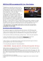
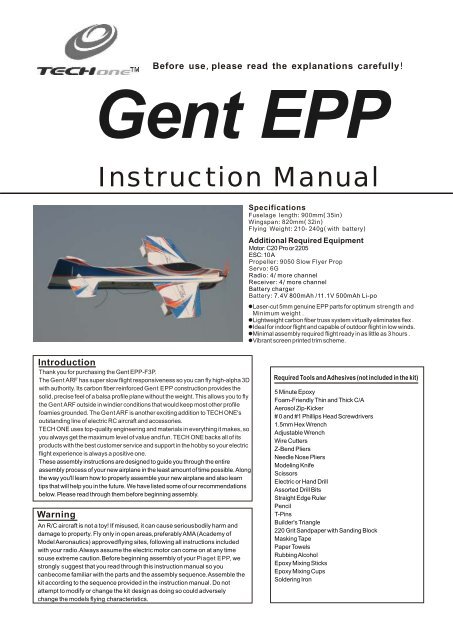
BeforeusepleasereadtheexplanationscarefullyGentEPP<strong>Instruction</strong><strong>Manual</strong>SpecificationsFuselagelength900mm35inWingspan820mm32inFlyingWeight210240gwithbatteryAdditional Required EquipmentMotor: C20 Pro or 2205ESC: 10 APropeller9050 Slow Flyer PropServo6GRadio4 more channelReceiver4 more channelBattery chargerBattery7.4V 800mAh /11.1V 500mAh Li-poLaser-cut 5mm genuine EPP parts for optimum strength andMinimum weight .Lightweight carbon fiber truss system virtually eliminates flex .Ideal for indoor flight and capable of outdoor flight in low winds.Minimal assembly required flight ready in as little as 3 hours .Vibrant screen printed trim scheme.IntroductionThank you for purchasing the Gent EPP-F3P.The Gent ARF has super slow flight responsiveness so you can fly high-alpha 3Dwith authority. Its carbon fiber reinforced Gent EPP construction provides thesolid, precise feel of a balsa profile plane without the weight. This allows you to flythe Gent ARF outside in windier conditions that would keep most other profilefoamies grounded. The Gent ARF is another exciting addition to TECH ONE'soutstanding line of electric <strong>RC</strong> aircraft and accessories.TECH ONE uses top-quality engineering and materials in everything it makes, soyou always get the maximum level of value and fun. TECH ONE backs all of itsproducts with the best customer service and support in the hobby so your electricflight experience is always a positive one.These assembly instructions are designed to guide you through the entireassembly process of your new airplane in the least amount of time possible. Alongthe way you'll learn how to properly assemble your new airplane and also learntips that will help you in the future. We have listed some of our recommendationsbelow. Please read through them before beginning assembly.WarningAn R/C aircraft is not a toy! If misused, it can cause seriousbodily harm anddamage to property. Fly only in open areas,preferably AMA (Academy ofModel Aeronautics) approvedflying sites, following all instructions includedwith your radio.Always assume the electric motor can come on at any timesouse extreme caution.Before beginning assembly of your Piaget EPP, westrongly suggest that you read through this instruction manual so youcanbecome familiar with the parts and the assembly sequence.Assemble thekit according to the sequence provided in the instruction manual. Do notattempt to modify or change the kit design as doing so could adverselychange the models flying characteristics.Required Tools and Adhesives (not included in the kit)5 Minute EpoxyFoam-Friendly Thin and Thick C/AAerosol Zip-Kicker# 0 and #1 Phillips Head Screwdrivers1.5mm Hex WrenchAdjustable WrenchWire CuttersZ-Bend PliersNeedle Nose PliersModeling KnifeScissorsElectric or Hand DrillAssorted Drill BitsStraight Edge RulerPencilT-PinsBuilder's Triangle220 Grit Sandpaper with Sanding BlockMasking TapePaper TowelsRubbing AlcoholEpoxy Mixing SticksEpoxy Mixing CupsSoldering Iron
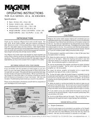
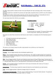
3Kit ContentsFuselage side board 1Fuselage main board 1Wing with Ailerons 1Horizontal Elevator 1Rudder 1Wing damping plateEPP 2Landing Gear Struts 2.0180mm2Doublers with Round Hole EPP 2Wheel CoversEPP2Main Gear Wheels 2Carbon Fiber Strips1.0800mm2Carbon Fiber Strips1.0400mm1Carbon Fiber Strips1.0100mm4Carbon Fiber Rods 1.0500mm 7Carbon Fiber Rods 1.3700mm 2Plywood Pushrod Supports 2Steel wire 0.8360mm 1Control Horn Backplates 4Control Horns 4Heat-Shrink Tubing 1Wood Screws 4Plywood Motor Mount 1Motor MountEPP1HeadStrengthenPlatesEPP2Hinges15Clevis8Velcro 11ElevatorStick the carbon strips on theelevatorwithsome foam-friendly C/ACuta 45bevel into the bottom leading edgeof the elevator.78mm 78mm78mmdepth3mmCut four 12mm long slots, then put the hinges into the slot s, fixed with some foam-friendly C/A1
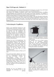
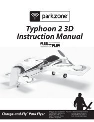
32WingStick the carbon strips on thewingwithsome foam-friendly C/ACuta 45bevel into the bottomleading edge of the wing.105mm105mm105mmSame as assemblyof elevatordepth3mmlength12mm3FuselageABABCut two 100mm long carbonstrips , then put them into the slotsof the h ead,fixed with somefoam-friendlyC/AGlue the wings with aileron to the main fuselage.NoticeMeasure from the tipsof the wing to the rear of thefuselage. The measurementsmust match from right to left. If not,adjust the position ofthe wing until both measurements are equal.CASame as above stepsBoth sides of thefuselage side board90msfuselage side boardmfuselage main boardS2
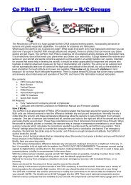
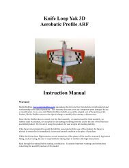
34Rudder57mm 57mmCuta 45bevel into the bottomleading edge of the rudder.depth3mmlength12mmSame as assembly of elevatorF ixed with some foam-friendly C/A5BracingCut the two carbon rods. One end Position the carbon rods in theof the carbon rod is fixed into the fuselage, gluing the rods to thehole of the fin with the foam vertical fuselage ONLY. This willfriendly CA and the other end is allow for alignment of the fuselagefixed into the holeofthefuselage in the next step.Make sure they are verticalSame as above stepsHold the two carbon rodstogether with a line andsome C/AIt is similar to assemble the fuselage bracing, as you want the rods to beglued to the carbonbracing that has been preinstalledon the wing and fuselage. The rods are staggered andfit intonotches in the fuselage. Make sure the rodsare straight and are not flexing the wing. Use foamfriendlyC/Ato glue the rods in position. The wingshould be flat and parallel to the horizontalstabilizer,while also being perpendicular to the vertical fuselage. Use side cutters to trim away any3
6Servosanditsconnecting bar aileronservorudderservoelevatorservoUse a dab of foam-friendly thick C/A to securethem into place.Because the size of servosdiffers, you may need to cut the servo mountinghole larger to fit your particular servos.Plywood PushrodSupportsFixed on the fuselage side boardwith some foam-friendly C/ASecure one piece of wire to one end of the carbon fiberrod, using onepiece of heat-shrink material. The pieceof wire should overlap the carbonfiber rod at least 1"(25mm). Heat the heat-shrink material with a heat gunto shrink it into place.PRO TIP For extra security, applya few drops of foam-friendly thin C/Ato the end of thepushrod and allow it to "wick" into the joint.4
7MotorGlue the firewall to the head of the plan.F ixed with some foam-friendly C/AAssemble the motor onto the firewall, using the fourwood screws provided.PRO TIP After flying theairplane, you may want to add right and/or downthrust to the motor. You can do this by adding thinwashers between the motor mount and the firewall.8FinalAssembly F ixed with some foam-friendly C/AFixed with some foam-friendly C/A5
9Landing GearF ixed with some foam-friendly C/A10ControlSystem Mount your ESC to the fuselage,using a piece of velcro .Mount your receiver to thefuselage side, using a pieceof velcro.Assemble your battery into thebatterycompartment, using apiece ofvelcro.Plug the servo and ESC leads into their proper slots in your receiver,then mount your battery to thefuselage, opposite the ESC.Run the antenna out the bottom of the fuselage and secure it along itslength, using pieces of clear tape (not included). Do not cut the antenna shorter. Allow the excess tohang beyond the back of the fuselage.6
Motor ThrustTo ensure great flight performance and to be ableto trim your airplane properly, it is critical that youadjust the motor thrust as described. We suggestthat you add 2 degrees of down-thrust and 1degrees of right-thrust. This can be achieved byadding a washer or two behind the top and rightside of the motor (between the motor and thefirewall). When set properly, the trim for theelevator and the rudder should be neutral. Finetunethe down-thrust and right-thrust until this trimis achieved.Balance PointThe Center of Gravity (C/G or Balance Point) is 315"(80mm) from the leading edge of the wing, measured atthe center of the wing.WARNING For test flying and general sport flying, wesuggest you balance the airplane at the C/Grecommended above. For 3D flying, you may want toexperiment moving the C/G back in small incrementsuntil you're satisfied with the result.ExponentialSport FlyingAilerons: 20%Elevator: 20%Rudder: 20%3D FlyingAilerons: 35% - 50%Elevator: 35% - 50%R udder: 35% - 50%Exponential softens the response of the controlsurfaces around neutral stick. This makes theairplane easier to control while using such largecontrol throws. The Exponential values shown aregiven as a percent. Please note that differentbrands of radio control systems may call for + or -Expo. Please check your transmitter's ownersmanual for more info.Seek AssistanceIf you are new to R/C we suggest you find an experienced pilot to check out your aircraft and help you withthe first few flights.This will help prevent damage to your model and will speed up the learning processmaking your R/C experience all the more enjoyable. You can contact local R/C clubs or your dealer toobtain the names of experienced R/C pilots who would be Willingto help you with your first few flights.Although this is an ARF (Almost-Ready-to-Fly) kit, it does have some construction features that can bechallenging to the less experienced modeler. If you encounter difficulty in any constructionsequence,please feel free to contact one of ourtechnicians, we stand ready to provide any assistance we canconcerningthe construction of your Assuage 3D. Contact us at:EMail: techonehobby@gmail.comCopyright2008TechonehobbyHttpwwwtechonehobbycomMadeinChinaCTM7