
You also want an ePaper? Increase the reach of your titles
YUMPU automatically turns print PDFs into web optimized ePapers that Google loves.
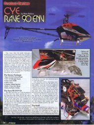
Moving the CG aft, within reason, can help knife edge. An easy wayto test CG is to trim the plane for level flight at about 1/2 throttle,and roll the plane inverted. If the plane pitches down (toward theground) significantly, you should be able to move the CG aft. It's bestto move it in small amounts, otherwise the plane could get verysensitive in pitch (sensitive to elevator movement).I don't know what prop you're using but a prop smaller in diameterand larger in pitch will also help. For example, a 13-8 will yield morecontrol from the rudder and elevator than a 14-6 (the air column fromthe prop moves faster over the control surfaces).With a few adjustments, that plane and engine should be capable <strong>of</strong>knife edge flight. It may take full throttle, but it should hold atleast level flight in the knife.Q.I've heard you can dye canopies with Rit dye. I had some black liquid Rit laying around and had no success with it.I washed the canopy thoroughly, heated the dye, and left it in for a long time, but it came out clear. Does it have tobe the powdered type to work?A.No, it doesn't have to be powdered. I've used both with success!Your problem is the canopy material. Some plastics used for canopieswill NOT take a tint, no matter how long you soak it in Rit dye, otherswill take a tint but will warp badly... ask me how I know! ;-)By the way, I've discovered that if you add about a teaspoon <strong>of</strong> tablesalt to the water/dye mixture, it seems to help the plastic take thetint quicker... assuming it will take the tint at all. It's definitelybest to test a scrap <strong>of</strong> the canopy plastic (that which is left overafter trimming) to see if it will dye or not, and also whether it willwarp in the hot water.Q.My servo is buzzing why ?A.I would test by figuring out which servo(s) are buzzing, then work thecontrol surfaces with the radio and by hand to see if I could make theservo stop buzzing. If you can make the servo stop buzzing by simplysupporting the weight <strong>of</strong> the control surface, you might want a morepowerful servo. If that doesn't help, pull the control horn(s) <strong>of</strong>f theservo(s) and see if they still buzz. Replace them if they do. There'sinternal binding that might cause premature airframe death should theservo fail.Q.Measuring WashoutA.Washout, the downward twist in wingtips that improves low-speed flight, is sometimes used in airplanes with flatbottomwings. A good way to make sure each wingtip has the same amount <strong>of</strong> washout (or any at all) is to get twostraight wood dowels or carbon rods. Tape each to the bottom <strong>of</strong> the wing near the tips. Set the wing on somethingso you can see both rods, and sight down the wing so you can see each rod in relation to the other. The rodsmagnify any angle that might be present in the wing. Correct the wing twist until you have the angle you want. Thisdoesn't work too well with wings that are rounded on the bottom, but is an excellent way <strong>of</strong> making sure flat-bottomwings are true.
Q.4 <strong>Tips</strong> about EpoxyA.1. Wax Paper: Take a sheet <strong>of</strong> wax paper, and mix your epoxy on half <strong>of</strong> the sheet. Then when done, fold the waxpaper in half, trapping the epoxy residue inside. This way you can fold it up with no mess and throw it away, and itwon't stick to the inside <strong>of</strong> the trash can.2. Foam: When epoxying to styr<strong>of</strong>oam, such as attaching leading or trailing edges to a foam-core wing, once theparts are coated well with epoxy and put together, wiggle them around some to work the epoxy into the pores <strong>of</strong> thefoam. Then let it dry normally. This results in a stronger bond.3. Bed-Buddy: Ever been caught with cold epoxy? It's much more workable and mixes better when its just aboveroom temperature (about 80-85 F). I use a "Bed-Buddy" to warm it and keep it warm. A Bed-Buddy is like a longsock with some kind <strong>of</strong> granular chemical in it that stays warm for hours after you microwave it for two minutes.They're designed to keep your feet warm at night, and you can wrap it around your epoxy bottles too between eachuse. You can also put the epoxy bottles directly in the microwave oven for a short time, but be careful doing it.4. Inverter: When your epoxy bottles start getting low, it can take a while to get it out, especially when cold. Build asimple wooden "inverter" to hold both bottles upside down, and keep them in it between each use. This way yourepoxy will always be ready for use.Q.Servo BlanksA.Here's an easy way to make sure your servos will fit in your plane properly, especially helpful with scratch-builtdesigns: Take the measurements <strong>of</strong> your servos, and make a few from wood, identical to the real ones. This maybe easy if the manufacturer supplies full-size drawings <strong>of</strong> the servos. I made my servo blanks from pine blocks, alittle plywood for the mounting hole piece, and a dowel for the motor shaft. These servo blanks will not only help indrilling the holes to mount servos, but will assure adequate clearance on all sides. In addition, the dowel is thecorrect size to press on an actual servo arm, which will help in aligning pushrods or cables. Using this method willhelp keep your real servos safe and clean during the building process.Q.Vertical Fin AlignmentA.To get a fin in correct alignment with a fuselage, try using thread. Make sure you have an accurate center marknear the top-front <strong>of</strong> the fuselage, and tack-glue a long piece <strong>of</strong> thread to the top near the nose, a distance from thecenterline equal to half the thickness <strong>of</strong> the fin. Run the thread back to the tail, and hold it against the side <strong>of</strong> the fin.The thread should touch the side <strong>of</strong> the fin evenly overall. If it doesn't, then rotate the fin until it does, then tack gluethe fin into place, reinforcing it later. Last, remove the thread you tack-glued.Q.Keeping Knives and Blades Safe in StorageA.Get a small block <strong>of</strong> styr<strong>of</strong>oam and stick your hobby knife in it. This way the blade won't be exposed, and you won'tcut your hand if you reach into a drawer or box for it. Always keep new blades in their original container, and throwaway used blades into a closed can with a slot cut in the top, don't just throw them into the trash can bythemselves.Q.Sharp PropsA.Most propellers have very sharp edges when new, especially at the trailing edge, which can cut your fingers.
Always sand the edges smooth with fine sandpaper as soon as you buy them. Be extra careful when turning oversomeone else's motors by hand, because they might not have sanded the edges <strong>of</strong> their props.Q.Extra-Long ScrewsA.If you need an extra-long screw or bolt for something, such as a wing tank or mid-mounted wing, make one bycutting the correct size threaded rod you need, then solder a wheel collar on one end. Next, using a cut-<strong>of</strong>f wheel,cut a slot in the wheel collar for a screwdriver.Q.Engine Mount/NosegearA.If you have a small plane with a very tight engine installation (usually resulting from a very streamlined cowl), <strong>of</strong>tenthere's no room for a nose gear assembly. Try drilling holes through the engine mount to accept the nose gearwire, and hold it in place with wheel collars. The steering arm can be placed below the engine, even on the outside<strong>of</strong> the plane. This will work with most engine mounts, even the two-piece ones as long as the engine is rotated 90degrees.Q.Setscrew GrippingA.Ever have wheel collars not hold on axles? Or maybe that nose gear keeps twisting because the steering arm won'ttighten? Try grinding or filing a flat spot on the wire where the setscrew will go. This provides a better surface forthe screw to tighten against. Better yet, grind a flat spot with a small diameter (worn out) cut-<strong>of</strong>f wheel. The smalldiameter causes the flat spot to actually be concave, which helps the setscrew grip even more.Q.Parts From Plastic Soda BottlesA.Several things for <strong>RC</strong> airplanes can be made from 1, 2, or 3-liter soda bottles.• Use the colored base that come with some bottles for cowls. They're sized about right for .15 to .25engines.• On bottles that have the base molded into the bottom, cut the bottom <strong>of</strong>f, and this can become a "standway-<strong>of</strong>f"5-cylinder radial dummy engine when painted properly.• The cylinder that's left after cutting <strong>of</strong>f the top and bottom <strong>of</strong> bottles can be used to form canopies andother parts. This plastic shrinks easily with a heat gun and can be molded around wooden forms.Take the colored base <strong>of</strong>f <strong>of</strong> a 1-liter bottle, which should leave a hemisphere at the end. Glue fins on theother end, paint it, and you have a bomb for a large airplane. And if you want to drop it, it probably won'tbreak.Q.Curving BalsaA.Get some ammonia, found in the household section <strong>of</strong> the supermarket. Put some in a spray bottle, and spray bothsides <strong>of</strong> balsa sheet liberally. Carefully bend the sheet to the right shape. You can even tape it to a form, such asaluminum soda cans, and let it dry. Once dry, it may be used as turtle-decks, etc.
Q.Wing-Tail AlignmentA.Get an old (but straight) telescopic antenna, the same type as on transmitters. Use it as an adjustable-lengthmeasuring rod to compare critical measurements on planes during construction. I use this idea to compare thedistance from one wingtip to the stabilizer, and to make sure this distance is equal on both sides <strong>of</strong> the plane. Thisensures that the stabilizer is parallel to the wing.Q.New Pilot TipA.Something to pay attention to when learning to fly is control reversal. Control reversal is when the inputs on thetransmitter sticks must be reversed when your plane is flying toward you, rather than away from you.When flying away from you, there is no problem, just move the stick in the direction you want to turn.Many new pilots become disoriented when their plane is approaching them. To help with this, move the stick intowards the low wingtip. This will level the wing when your plane is coming toward you, avoiding a sharp bank, andpossibly a crash.Example: Say your plane is coming toward you, and the right wingtip is low, as if banked to the right. Move the stickto your left, toward the low wingtip. This will bring the plane's right wingtip up, and level the wing.Q.Installing Triangle StockA.For me, triangle reinforcements have always been difficult to handle due to their shape, especially if they're coatedwith epoxy.Try sticking your Xacto knife loosely into one end <strong>of</strong> the triangle. Then lay it on the bench so that the wide part <strong>of</strong>the triangle (the hypotenuse) is against the bench top. Now apply the epoxy or other adhesive to the sides that willcontact the airframe.Next, by using the knife handle, insert the triangle into position in the airframe. Press down with your finger onto thewide side that has no glue, and carefully slide the knife out <strong>of</strong> the piece.This way you can cleanly install triangle stock, and not get any glue on your fingers.Q.Ralph's Rib MakerA.Here's what Ralph did to make all those wing ribs for the Joker's Wild planes:Cut two ribs from 1/16-inch steel. Drill two holes along the center line, one near the leading edge, one near thetrailing edge, for 1/4-inch bolts to pass through. Make sure both steel ribs are identical.Use a steel rib as a template to draw ribs onto balsa sheet. Leave room around each rib. Cut each rib "block" out <strong>of</strong>the sheeting, and drill the holes in each.Assemble all ribs on the correct length bolts, and sandwich all between the steel ribs. Using nuts, tighten theassembly down, making sure it's straight.
Now, using a belt sander (a disk sander will work too), remove the extra wood around the ribs down to when thesteel begins touching the sander. Cut out the spar notches with a hand saw, and clean them out with a file.This will make all the ribs for a wing at once, and they'll all be identical, resulting in a straight, uniform wing. It canalso be used for a tapered wing (with all the ribs <strong>of</strong> different size), and bulkheads and formers can be made usingthis method too.Q.Sandbag WeightsA.Fill plastic zip-lock bags <strong>of</strong> various sizes about 3/4 full <strong>of</strong> fine sand, and seal each well.Use these to hold down large parts while building, such as wings. The sand will conform to the shape <strong>of</strong> parts well.They also work good when gluing sheeting to foam.Q.Air-Bleed ScrewsA.When adjusting air-bleed carburetors (the ones with the little hole in the front), a good rule to remember is the word“richen”. Split this word in half (rich-en), and when you want the carburetor rich, turn the screw in. Of courseleaning the carburetor would be turning the screw out.Q.Measuring Balsa DensityA.Knowing the density or weight <strong>of</strong> balsa pieces can be important. It's especially useful when making ailerons orwingtips, because you want the pieces to be "matched", which will result in a better balanced and better flyingairplane. To do this, choose balsa that is similar in weight by weighing them on a gram scale. If you don't have agram scale, use the deflection method: Take the balsa pieces, and using heavy weights or sandbags, hold down afew inches <strong>of</strong> one end <strong>of</strong> each balsa piece onto the edge <strong>of</strong> a table. Make sure that equal amounts <strong>of</strong> each piece <strong>of</strong>balsa overhang the edge. Place a smaller weight onto the other end <strong>of</strong> each piece, and measure how far each onebends from the floor. The one that bends the most generally is the lighter piece. Using this method, you can choosebalsa that is similar in density. Keep in mind that if you build from kits, you don't have to use the supplied wood ifyou don't like it!Q.Transmitter Neck StrapsA.If you use a neck strap on your transmitter, beware <strong>of</strong> getting it caught in a rotating propeller! Some people leavethe strap around their neck and detach the transmitter while starting engines. This is a perfect way for it to getcaught in the prop, especially if you start your planes on the ground rather than a stand or table. Also, having thetransmitter nearby while starting an engine is potentially a hazard. When you pick up the transmitter make sure thestrap doesn't swing into the prop.Q.3-Blade PropsA.3-blade propellers are useful when you have a scale plane that's modeled after a plane that uses them. However,since the engine has more mass to turn, the maximum RPM is lower. The general rule is to use a 3-bladed prop
one inch smaller in diameter than the 2-blade you would normally use. This will allow close to the same maximumRPM as you would have with a 2-bladed prop. You may also increase the pitch by one inch, but experiment andsee what works best with your engine and plane.Q.Firewall Fuelpro<strong>of</strong>ingA.Firewalls <strong>of</strong> planes are normally coated with epoxy to help prevent fuel and oil damage to the wood. On planes withno cowling, apply a coat <strong>of</strong> epoxy on the firewall after you cover the plane with film covering. Make sure the filmoverlaps a little onto the firewall. This way the epoxy seals the edges <strong>of</strong> the film covering. Besides, most filmadheres better to wood than epoxy, so that's another plus.Q.Ultracote PrintingA.Goldberg Ultracote film covering has a paper backing that you can print on. Cut a 8.5 X 11 inch sheet, put it in aninkjet printer, and print your design on the paper backing (don't use a laser printer or anything that uses heat - it'lldestroy your covering). This works well for large lettering. Make sure your image is reversed, so that when it'sprinted on the backing you can cut it out and it'll be correct when ironed on your plane. If you want to use a piece <strong>of</strong>covering that's smaller, print the design onto paper first. Then carefully tape the Ultracote to the paper over thedesign. Then run the whole thing through your printer, and the design should print in the same place.Q.Cutting Dowels StraightA.When cutting a dowel, it's easy to make the cut crooked. To help ensure a nice 90-degree end, especially on largerdiameters, try rolling the dowel into the band saw or scroll saw blade.Q.Picking up Glass SafelyA.After sweeping up broken glass <strong>of</strong>f your shop floor, it's difficult to pick up tiny fragments. Try making a loop <strong>of</strong> ducttape, adhesive side out. Place the loop over your hand, and pat the fragments carefully so they stick to the tape.Then just throw the tape loop in the trash.Q.Antenna HolderA.Here's a way to attach a receiver antenna to the back <strong>of</strong> your plane after it exits the fuselage. Take a short length <strong>of</strong>fuel tubing and make two cuts into it, dividing it into thirds, but make the cuts go through the tubing only halfway.Then pin the tubing to the top <strong>of</strong> the plane's fin. Thread the antenna through the tubing, lacing it through the cuts.This will keep the antenna somewhat taught and out <strong>of</strong> the way <strong>of</strong> control surfaces.Q.Converting Cubic Inches to cc's
A.Sometimes there's a need to convert cubic inches to cubic centimeters (cc) or vice-versa where enginedisplacement is concerned. One cubic inch is equivalent to 16.39 cubic centimeters. So to convert from in3 to cc's,just multiply the in3 by 16.39 to get cc's. To convert cc's to in3, divide the cc's by 16.39 to get in3. And remember, a7.5cc engine is the same as a .46 (pretty close).Q.Repairing Dings & DentsA.Have you ever had a dent in a balsa leading edge? Try fixing it with water! Get a small diabetic syringe and putwater in it. Inject a little water into the balsa into and around the dent in the leading edge. Heat the area with yourcovering iron. When the water starts boiling, it will build pressure and push the balsa out to its original shape.(Courtesy Victor A.)Q.Film Covering DegreaserA.Have you ever wanted to add more film covering (Monokote, Ultracote)to a plane you've already flown? It's difficultto get all the oil exhaust <strong>of</strong>f the plane so the film will stick. Try using Cyanoacrylate (CA or superglue) kicker(catalyst). Just spray it on and wipe it <strong>of</strong>f. I've been told it's a very good degreaser. (Courtesy Vince R.)Q.Pull Oil out <strong>of</strong> WoodA.Sometimes firewalls and engine areas <strong>of</strong> older planes get soaked with oil from the fuel. This weakens glue joints tothe point where a plane could fall apart in midair. Try using Cyanoacrylate (CA or superglue) kicker (catalyst). Justspray it on and wipe it <strong>of</strong>f. I've been told it pulls the oil right out <strong>of</strong> the wood. Several treatments may be necessary.This also works if a fuel tank develops a leak and the fuselage gets soaked with fuel. (Courtesy Jevan F.)Q.Balancing PlanesA.Here's a good way to balance airplanes. While building your plane, insert a half-inch square piece <strong>of</strong> plywoodwhere the balance point should be. For a low wing, this should be on the bottom <strong>of</strong> the wing, and for a high wingthis would be on top <strong>of</strong> the wing (Note: sometimes something will be in the way, like a canopy, and you can't usethis technique). When the plane is finished, put a small hook into the plywood and suspend the plane with wire orstring. This way you can check the fore-aft balance AND the lateral balance at the same time (Note: a low wing willbe suspended inverted).Q.Fiberglassing Wing CentersA.Whenever I fiberglass a wing center section, I've found it's difficult to get the fiberglass cloth to lay flat after it's beenfolded in a bag. Here's two ways to make this easier: (1)Use thin CA to tack it down. You may saturate the wholecloth with thin CA, or apply epoxy. On foam wings, make sure you use CA safe for foam. (2)Give the cloth a lightspraying <strong>of</strong> 3M Spray Adhesive, then apply it to the wing. I've found this method to work extremely well, and it'ssafe for foam. Then apply the epoxy as usual.
Q.Control Horn InstallationA.When installing control horns onto control surfaces the screwdriver invariably slips. The result is a hole poked intothe covering material or a gouge in the balsa. There is a simple tool you can make that will eliminate this damage.Take a small piece <strong>of</strong> thin plywood and cut a rectangular opening in it just slightly larger than the base <strong>of</strong> the controlhorn. Place this opening around the control horn base before tightening the mounting screws. Now when thescrewdriver slips there will be no damage to your new aircraft! (Courtesy Fred H., Derby Radio Control Club, DerbyKansas)Q.Turning Wing BoltsA.If you use nylon wing bolts on your plane that take a slot screwdriver, and you forget your screwdriver, try using aquarter. A quarter is actually easier to use than a screwdriver, since it won't slip <strong>of</strong>f the bolt and damage your wing.What if you forget your quarter too? Usually you can get a quarter from loose change in your pocket, or your car.Q.Tail Wheel StrengtheningA.Tail wheels and their associated parts take a lot <strong>of</strong> punishment, especially on rough fields. Sometimes the "tiller"part <strong>of</strong> the wire that goes into the rudder breaks out. Here's two ways to strengthen it: 1. Put hardwood or plywoodinto the part <strong>of</strong> the rudder that the tiller goes into, a piece about half an inch square by the rudder thickness shoulddo for most planes. 2. Position the tiller so that it goes in-between the rudder control horn.Q.Deburring Brass TubesA.I use 1/8" brass tubing for fuel lines through firewalls. Silicone fuel tubing is connected to the brass on both sides <strong>of</strong>the firewall. To provide a better fit and extend the life <strong>of</strong> the silicone fuel tubing, carefully debur the ends <strong>of</strong> thebrass by running a hobby knife along the inside edge <strong>of</strong> the brass. Then use fine sandpaper to smooth the outsideedges. Since brass is a s<strong>of</strong>t metal, the fine sandpaper (about 220 grit) works very well.Q.Needle Valve ModificationA.On planes with cowlings, I modify the engine's needle valve so it can be adjusted inside while the engine isrunning. I grind the outside end <strong>of</strong> the needle valve flat. Then I cut <strong>of</strong>f the head <strong>of</strong> a hex bolt (either size 6 or 8), andsolder the head onto the end <strong>of</strong> the needle valve. Then you can stick a hex wrench through a small hole in thecowling to adjust the valve.Q.Foam CuttingA.When I buy a large (4 x 8 ft.) piece <strong>of</strong> foam, I like to cut a smaller piece <strong>of</strong>f before using the hot wire. My hot wireisn't big enough to use on a full sheet, so I use a reciprocating electric knife, the kind used for meat and bread. Itworks pretty well for cutting <strong>of</strong>f a usable piece.
Q.Wheel Axle BushingsA.If you have a wheel that's too big for the axle, make bushings from brass or aluminum tubing to make up the space.If you get tubing <strong>of</strong> the correct size, you can also make multiple bushings that fit inside each other, if that isrequired. Don't let wheels wobble! They'll wear out quicker, and make ground handling difficult.Q.Cleaning Airplanes WellA.If you have an airplane that you really want to take care <strong>of</strong> and look good for a long time, you have to occasionallyclean it really well. Do this by disassembling what you can (remove the wing and landing gear) and wipe it downwith alcohol from the drug store. This will remove fuel oil residue well. This is also a good cleaning for film coveringwhen you have to apply new film over old.Q.Empty Fuel BottlesA.If you purchase fuel in plastic bottles, when they're empty, put it in an out <strong>of</strong> the way place with the cap <strong>of</strong>f for abouta day. This will allow the residual fuel to evaporate. If you place the cap on without airing it out, you have a potentialbomb if an ignition source should ever penetrate the bottle. After the bottle is aired out, crush it, then replace thecap. Then recycle the plastic if you can at a recycling center. Many places don't take plastic, so if it does end up ina landfill, at least it will take up less space by being crushed. You should air out and crush metal fuel cans too.Q.Wheel Collar TighteningA.If you use wheel collars with the tiny hex setscrews (I think most <strong>of</strong> us do), sometimes while tightening them thehex wrench rounds <strong>of</strong>f a little, causing it to stick in the setscrew. So you end up turning the hex wrench to loosenthe wheel collar just to get the wrench out. But now the setscrew may not be tight anymore. To check it, just turn itwith your fingers. If it doesn't turn, it's tight enough. If you can turn it, try to tighten it more.Q. How do I make a V-Tail work ?A.If you have room in the fuselage an old trick is to use a sliding tray. The"rudder" servo sits in the sliding tray and is moved fore and aft by the"elevator" servo. Result: mechanical mixing <strong>of</strong> rudder and elevator (which iswhat a v-tail gives you). If you're interested in this idea (I've used itwith good success several times) let me know and I'll draw up a sketch. It'sreally quite easy to build but it does require some room in the fuse.The other suggestion would be to use one <strong>of</strong> the commercially availablev-tail mixers.Flaps
Along with undercarriages, flaps can be quite a challenge to rig in an appropriate and reliable manner. A review <strong>of</strong>possible configurations might be a good way to start.Plain flaps - hinged in a similar war to ailerons. These are the simplest to set up. Hinges can be <strong>of</strong> the flat plasticwith the metal pin variety, Robart Hinge Points, or plastic covering material on small powered models or gliders.Spotted flaps - more complicated, but can be more effective than plain flaps. The hinge line is below the wing sothat as the flap goes back and down a slot opens up between it and the wing. Some <strong>of</strong> the airflow goes through theslot producing more lift than does the plain flap. Hinges can be made from two control horns with 8 BA bolts as thehinge point ( as shown below). Robart Hinge Points can be also be used as flap hinges.The most common effect <strong>of</strong> flap operation commented on ( complained about ) is the pitch up usually experiencedon deployment. Flaps are fitted to enhance low speed handling so throttling back and slowing down before loweringthe flaps may reduce the pitch up. Radios with flap/elevator mixing almost completely eliminate this problem. Flapsincrease lift and therefor drag, making them useful for short, steep approaches. Airspeed need to be watched toprevent overly high rates <strong>of</strong> descent leading to heavy landings.Flap LinkagesThe simplest flap mechanism is flaperons which require an aileron servo in each wing mixed electronically t<strong>of</strong>unction as flaps as well. This set-up is commonly seen in fun fly machines, but any plane with strip ailerons can beset-up this wayThe two cases below show the conventional inboard flap/outboard aileron set-up. Set-up such as theseallow flaps with broader chords. I have read that flaps ( 25 - 30 % <strong>of</strong> wing cord ) produce smaller pitch upsthan narrower ones. Only driving the flaps via a torque tube. Air loads on flap surfaces can be quite highrequiring push rods to be straight and rigid. Ball joints can be used to minimize the "slop" that sometimesoccur with push rod end fittings.
These are but a few thoughts on the subject. Its an area where a great deal <strong>of</strong> experimentation can becarried out. Basic trainers lend themselves to this admirable and successful ideas can be used in scalemodels.Parallel Operation = Reliability & More Flight TimeThe use <strong>of</strong> redundant parallel fight packs (packs may be <strong>of</strong> different capacity but MUST be <strong>of</strong> an equal number <strong>of</strong>
(600-800 mAh AA packs)can be charged employing regular system wall chargers (1200 to 1600 mAh should covermost giant size projects).Taipan Glow PlugsAn article from Brain GardinerHow does a glow plug work ?Contrary to what many have previously been lead to believe the following is an explanation <strong>of</strong> how a glow plugfunctions in a motor. The plug is initially heated by applying a voltage ( Typically 1.5 Volts ) to it. This is to cause itto glow so as to ignite the fuel at compression and start the internal combustion cycle. Once the cycle has started ,the power source can be disconnected, as with the heat generated at combustion the CATALYTIC reactiongenerated between the methanol and platinum in the plug coils becomes sufficient to keep the process going.The catalytic reaction is a reaction whereby platinum will glow in the presence <strong>of</strong> methyl alcohol vapour. This willhappen without any external source being applied.How do you select the Correct plug for your application, and Why.To do this you need to understand a little more <strong>of</strong> the theory behind the process. In glow flue the catalytic reactionis generated between the methanol and platinum only. Castor oil, synthetic oil, nitro methane etc. do not generate acatalytic with the platinum.Next you need to understand that a certain surface area <strong>of</strong> platinum is required to generate a sufficient catalyticreaction to keep the internal combustion process going. Also it is necessary to allow extra surface area for thereaction to be great enough when it diminishes with the available methanol dropping as in the case at motor idle.Simply put, cold plugs are manufactured using a thicker wire to give greater surface area to facilitate a greater andthus the required catalytic reaction where less methanol is present in the fuel mixture.So! More nitro means less methanol which in turn means a greater surface area to platinum ill be required togenerate a sufficient catalytic reaction.Suddenly it all makes sense! To work out which temperature plug to use, you need to know how much methanol isin your fuel, Not how much nitro or oil. As a rough rule <strong>of</strong> thumb, 80% methanol or above, use a hot plug. 70% -75% use a medium plug. 60% - 75% use a cold plug. 65% or less use a very cold plug.Idle Bars and Other StuffAgain, contrary to what many believe, the idle bar on a glow plug is not necessarily what its name would suggest. Itis in fact to stop any fuel not vaporized from dousing the platinum coil <strong>of</strong> the glow plug by dispersing it away fromthe coil. Why are plated coils not as good as platinum alloy coils? Plated coils suffer from very quick degenerationas the plating breaks down under operation conditions. As bits <strong>of</strong> plating come <strong>of</strong>f, the plug is effectively becominga hotter and hotter until in a comparatively short time it is no longer able to perform its function.Conversely, a platinum alloy coil will still degenerate, but as it is platinum alloy throughout, the surface remains asplatinum alloy and the plug continues giving much the same characteristics for quite a long time.Plated coils are very poor value when compared to platinum alloy coiled glow plugs.Disassembling a Model Aircraft Glow EngineIntroductionThere is nothing magical about model airplane engines. The tolerances aren't even too critical, except on a fewmodels that beginners don't use. If you have an OS40FP and are curious about the insides, by all means, talk to aninstructor about it, maybe have him there watching you, and have a look inside. Again, there's nothing magical inthere, or even particularly delicate.I will say this. If you are afraid <strong>of</strong> engines and refuse to learn about them, you will be missing a large part <strong>of</strong>modeling, will make a lousy instructor (imo), and waste a LOT <strong>of</strong> money and flying time waiting for someone else toclean out your motor after a small crash. Well after you get the plane back together, you will still be looking in the
mail everyday, waiting for them to finish doing to your motor what you could have accomplished yourself in tenminutes.To take a typical model engine apart:1. Remove the glow plug.2. Remove the muffler.3. Remove the engine backplate. Save the gasket if there is one.4. Remove the cylinder head. Loose the screws in a criss-cross pattern. Save the gasket if there is one.5. Turn over the motor until the cylinder is down as far as it goes. Place a hardwood dowel or servo rail or such inthe exhaust port, so that it protrudes into the cylinder above the piston. Turn over the motor, and the piston shouldpush the sleeve up so that you can get a grip on it. Don't touch the sleeve with pliers, please. Remove the stick, butleave the sleeve sticking up out <strong>of</strong> the bore for now.5a. Note the orientation <strong>of</strong> the piston. There is <strong>of</strong>ten an arrow or some other mark on the piston face. Notice thisand remember it, or if you have to, use a grease pencil on the piston face to mark the position. You'll want to wipethis <strong>of</strong>f just before final reassembly, though.6a. If the engine has a separate front and rear crankcase, separate them. Save the gasket. The crank will stay withthe front half, and the connecting rod should now be free.6b. If the engine does not have a separate front and rear crankcase, and if it has rings, you should be able to slipthe connecting rod <strong>of</strong>f <strong>of</strong> the crankpin with the piston all the way down. If it doesn't have rings, you can pull thesleeve out, leaving the piston in the motor, then slip the rod <strong>of</strong>f the pin and remove the piston. When pulling out thesleeve, notice which way the ports are pointed. (This will be important for reassembly.) Don't use tools on thesleeve.7. Remove the carburetor from the engine.8. If you remove the prop nut and washer, the prop thrust washer (the knurled thing behind the prop) sometimesjust slips <strong>of</strong>f. On other engines you have to get a three-pronged gear-puller to get it <strong>of</strong>f. When it does come <strong>of</strong>f, becareful not to lose the woodruff key that sometimes comes out with it, and the brass bearing washer if it's there.9. At this point, the crankshaft will <strong>of</strong>ten just slip out. If not, it is a press fit, and is more difficult, and I don't suggestyou attempt it unless you have a hydraulic press. If you have a motor like this and need to replace the bearings,just send this assembly in for servicing.10. If it does come out, the next thing is the bearings, if you motor has ball bearings. The rear bearing comes out byheating the case in a 350degree oven for fifteen minutes, removing it with a pot holder, and rapping it on a piece <strong>of</strong>wood, rear <strong>of</strong> the motor down, and the bearing should just pop out. Careful not to burn yourself. Let it cool. Youshould then be able to use a steel rod or drift punch and tap out the front bearing from the rear <strong>of</strong> the motor.11. The piston comes <strong>of</strong>f <strong>of</strong> the rod by slipping the wrist pin out. That has probably slipped out by itself already,though. :-)Inspection:Bearings should have no rough spots, and no visible damage. This is a common malady. Also, you should feel noplay in them.Look for cracks anywhere, and replace the part if you find them. This is rarely necessary.Look carefully at the connecting rod. Look at the bearing surfaces at the end, and fit them on their respective pinsto look for play. This is common with older engines.The piston should have no scratches, only polished areas. Same for the inside <strong>of</strong> the sleeve. This would indicatedirt ingestion, and the piston and sleeve should be replaced.
If the piston has a ring, it should be polished, with no nicks, and obviously be unbroken. If you replace the ring, it'sa good idea to replace the sleeve, too, and vice-versa.The back plate will have marks from the crankpin. That's okay, as long as they are not deep scratches. This wouldindicate bad bearings or a torqued crank. Rare.Clean any crap out <strong>of</strong> the inside <strong>of</strong> the motor. Don't worry too much about the castor varnish--just use acastor/synth blend for a while. The motor should be spotlessly clean inside before reassembly.Assembly:1. Heat the case again (not the bearings). Push the bearings into their bores using a wood-padded vise and justenough pressure to move them, and no more. Oil them with castor or 3-in-1.2. Drop the crankshaft in. Oil. Hold it on there with the thrust washer, a prop hub, nut washer and nut.3. If you have a ringed engine, oil the piston, ring, and inside <strong>of</strong> sleeve. Find the pin in the ring slot, and place thering gap there. (That is the only way you can compress the ring all the way around. Press the ring in with yourfingers and slip the piston into the bottom <strong>of</strong> the sleeve. There should be a shoulder on the inside <strong>of</strong> the bottomedge <strong>of</strong> the sleeve to help you with this. Be gentle, it doesn't take force, and you can easily break the ring. Get theorientation right, same as you noted earlier.4a. If you had to remove the sleeve (6b, above) before the piston, just reverse the process. The sleeve will go ineasier if you oil the outside.4b. Otherwise, slip the sleeve in there (pay attention to orientation) and put the connecting rod on the crank pin.Make sure the ports all line up just perfectly. Push the sleeve up using the wood in the port and turn it if you haveto.(Oh, you needed to reattach the front and back crankcase halves in here somewhere. :-)5. Install back plate.6. Install cylinder head, criss-cross pattern on the screws. If there was a piston fence (a raised ridge on the pistonface), get the orientation <strong>of</strong> the head so the slot matches up to it.7. Install the carb. Push pretty hard when seating it; you don't want air leaks there.8. Glow plug.And there you have it. Maybe an hour, assuming you need to replace the bearings. Don't kill the screws, and usenon-permanent locktite if you are worried about them backing out.Dave Svoboda, Palatine, ILStorage <strong>of</strong> your Ni-Cd R/C Packs"How should I store my batteries at the end <strong>of</strong> the season? What should I do to them when I put them back inoperation?"The batteries should be removed from the transmitter and plane for longer term storage. Here in the south where alot <strong>of</strong> us work out <strong>of</strong> our garage work shops I recommend putting them in the refrigerator (not the freezer) during the<strong>of</strong>f season. While not so important where your workshop rarely gets above 23 degrees C (74 F) the refrigerator isstill a good bet. Why? The failure mode <strong>of</strong> Ni-Cds is separator failure, this is the material that keeps the plates fromtouching each other. When it fails the cell shorts. At higher temperatures it oxidizes faster. In fact, the rate doublesfor every 10 degrees C increase."Should I store my batteries charged or discharged?" It doesn't really matter, they will self discharge in a fewmonths stored at room temperature. If you are going to store them in the refrigerator the charge will remain for a lotlonger so I would discharge them first to 4.4 volts and them put them away. Good cells will just set there in thedischarged condition (the voltage can vary considerably but is usually above 1 volt). In a battery with damaged"worn out" separator in the cells, the cells are apt to short if left in a discharged condition. This is actually goodsince it is the first indication <strong>of</strong> a cell that's going bad and it is best to replace the pack. A battery left on trickle
charge will seldom short out since it is in the charged condition and any short that tries to develop will be zapped bythe charge in the cell. Partial shorts (those having fairly high resistance) can be developing that can cause the cellsto self discharge at a higher rate than normal and possibly leave you short in the middle <strong>of</strong> a flight after you justmeasured the cell when it came <strong>of</strong>f charge with your ESV and everything looked OK.The reason I recommend removing the batteries from the transmitter and plane is to protect against "black wire"disease. Should a cell short while in storage there is a high probability that there will be some leakage that can leadultimately to the "black wire" problem.Now when your batteries are coming out <strong>of</strong> storage, before charging, check the voltage without a load on thebattery. It should read well over 4.0 volts even if it has not been charged all winter. They should be essentially fullydischarged, flat as we say in the business. In this condition if the battery is going bad it will probably have shortedand you will read zero volts on that cell. It may be a s<strong>of</strong>t short, one that could be blown away merely by the simpleaction <strong>of</strong> slow charging. Don't do it! It is just lying there waiting to bite you. Replace the pack. Cut out the "good"cells if you want and use them in something less critical than your model. If you have access to a cycler runningthough a couple <strong>of</strong> charge/discharge cycles is a good idea just to make sure you are getting the capacity you aresuppose to. Anything less than 80% <strong>of</strong> rated is suspect. Once at the field, pre-flight battery checks are in order,particularly at the beginning <strong>of</strong> the season. Since those that religiously check their flight packs with an expandedscale volt meter seem to crash less (due to battery failure) one must assume that the ritual is smiled upon by theR/C Gods.Now, back by popular demand, the pattern trimming chart:This chart was set up for trimming a pattern plane. However, there are quite a few sport aerobatic planes thatwould fly better if they were set up like pattern planes. It's a lot easier to fly a plane that's properly set up than aplane with all kinds <strong>of</strong> perverse mixing. I also must give credit where credit is due, this chart comes from theNS<strong>RC</strong>A (National Society <strong>of</strong> Radio Controlled Aerobatics) newsletter and was submitted by Mike Chipchase <strong>of</strong>Australia. Some <strong>of</strong> this information is repeated from the last article on trimming for aerobatics.First let's talk about basic airplane setup. The latest pattern designs are set up with 2.5 degrees <strong>of</strong> right thrust, 0degrees down thrust, .5 degrees positive incidence on the wing (root and tip, no washout), and 0 incidence on thestab. Or, .5 ~ 1 degree down thrust and 0 incidence on the wing. Use an incidence meter to check this, or block theplane up on a big flat table and use a scale accurate to 1/32nd <strong>of</strong> an inch. If the plans show this information usethat as a starting point.Control throws should be set up as shown on the plans. It's very important each aileron to have the same throw.This should be setup mechanically. The aileron throws should be set up the same up and down. If the plane hassplit elevators make sure that each elevator half has the same throw as the other half. I usually set the plane upwith more down elevator than up elevator. That way I'll have the same control authority for up or down elevator. Setup the rudder with about 30 ~ 35 degrees <strong>of</strong> throw. Of course the ailerons and the elevator need to be gap sealed.To start out, the CG should be placed as shown on the plans, or about 30% <strong>of</strong> the average chord. The CG can beadjusted later. Use the placement <strong>of</strong> the radio to place or move the CG if possible. This is better than addingunnecessary weight because light airplanes fly better than heavy ones. Since the battery pack is the heaviest part<strong>of</strong> the radio, its placement will have the biggest affect on the CG. Also, laterally balance the plane. Pick it upunderneath the center <strong>of</strong> the spinner and underneath the center <strong>of</strong> the tail. Place weight on the light wing tip untilthe plane balances. Embed the weight in the wing tip.With all that in mind here’s the chart.-----------------------------------------------------------------------To test for | Test procedure-----------------------------------------------------------------------Observations | Adjustments-----------------------------------------------------------------------Control Neutrals | Fly model straight and level-----------------------------------------------------------------------Trim for straight and level | Adjust clevices to center transmitter| trims.-----------------------------------------------------------------------Control throws | Fly model and apply full deflection| <strong>of</strong> each control in turn.-----------------------------------------------------------------------Check the response <strong>of</strong> each | Aileron Hi-rate 3 rolls in 4 sec.control | Lo-rate 3 rolls -n 6 sec. Elevator
| Hi-rate to give a smooth square| corner. Lo-rate for a loop <strong>of</strong> 130 ft.| diameter. Rudder Hi-rate for stall| Lo-rate to maintain Knife edge| flight.-----------------------------------------------------------------------Decalage (incidence) | Power <strong>of</strong>f vertical dive, cross wind| any. Release controls when model| vertical.-----------------------------------------------------------------------A. Does model continue straight | A. No adjustmentsdown |B. Does model start to pull out | B. Reduce incidence(nose up) |C. Does model tuck in (nose | C. Increase incidencedown) |-----------------------------------------------------------------------Center <strong>of</strong> gravity | Roll model inverted-----------------------------------------------------------------------A. Lots <strong>of</strong> down elevator | A. Add weight to tail.required to maintain level |flight. |B. No down elevator required to | B. Add weight to nose.maintain level flight or |model climbs. |-----------------------------------------------------------------------Tip weight, course adjustment | Fly model straight and level upright| Check aileron trim maintains wing| level. Roll model inverted, wings| level. Release aileron stick.-----------------------------------------------------------------------A. Model does not drop a wing | A. No adjustment needed.B. Left wing drops | B. Add weight to right tip.C. Right wing drops | C. Add weight to left tip.-----------------------------------------------------------------------Side thrust | Fly model away from you into any wind| Pull into a vertical climb (watch as| the plane slows down.)-----------------------------------------------------------------------A. Model continues straight up | A. No adjustment needed.B. Model veers left | B. Add right thrust.C. Model veers right | C. Reduce right thrust.-----------------------------------------------------------------------Up/Down Thrust | Fly model on normal path into any| wind. When model is straight out from| you about 100 meters away, pull into| a vertical climb and release the| elevator.-----------------------------------------------------------------------A. Model continues straight up | A. No adjustment needed.B. Model pulls to canopy (up) | B. Add down thrust.C. Model pulls to belly (down) | C. Reduce down thrust.-----------------------------------------------------------------------Tip weight, fine adjustment | Fly the model away from you into any| wind and pull into a small diameter| loop.-----------------------------------------------------------------------A. Model comes out wings level | A. No adjustment needed.B. Right wing low | B. Add weight to left tip.C. Left wing low | C. Add weight to right tip <strong>of</strong> remove| from left tip.-----------------------------------------------------------------------Aileron differential | Fly model on a normal pass and do 3| or more rolls.-----------------------------------------------------------------------A. Roll axis on model | A. Differential OKcenterline |B. Roll axis <strong>of</strong>f to the same | B. Increase Differential
side <strong>of</strong> model as roll |command. |C. Roll axis <strong>of</strong>f to opposite | C. Decrease Differentialside <strong>of</strong> model as roll cmd. |-----------------------------------------------------------------------Dihedral | Fly model on normal pass and roll| into knife edge flight. Maintain| with top rudder (do this test to the| right and left sides)-----------------------------------------------------------------------A. Model does not roll out <strong>of</strong> | A. Dihedral OK.knife edge. |B. Model rolls in direction <strong>of</strong> | B. Reduce Dihedralapplied rudder. |C. Model rolls opposite the | C. Increase Dihedralrudder in both tests. |-----------------------------------------------------------------------Elevator Alignment. | Fly model straight away into any| wind. Pull into an inside loop.| Roll inverted and push into an| outside loop.-----------------------------------------------------------------------A. No rolling when elevator | A. Elevators correctly aligned.applied. |B. Model rolls in same direction | B. Elevator half misaligned. Raisein both tests. | half or lower the other.C. Model rolls in opposite | C. One elevator half has more throwdirections in both tests | then the other. (Model rolls to| the side with the most throw.)| Reduce the throw on one side or| increase it on the other side.-----------------------------------------------------------------------Pitching in knife edge flight | Same as dihedral test.-----------------------------------------------------------------------A. No pitch up or down | A. No adjustment needed.B. Model pitches up (to canopy) | B. Alternate cures.| 1. Move the CG aft.| 2. Increase the wing incidence.| 3. Drop the ailerons.C. Model pitches down (to belly) | C. Reverse the above-----------------------------------------------------------------------Notes: Trimming must be down in calm conditions. Make multiple tests before making any adjustments. If anychanges are made go back over the previous steps and readjust as necessary.Well, there it is. For the purists out there you might note that none <strong>of</strong> these adjustments require the use <strong>of</strong> acomputer radio. A well designed, well built aerobatic plane can be set up very close to perfect without any mixing.In fact that is one measure <strong>of</strong> a well designed pattern plane.I hope this helps any one out there that is interested learning advanced aerobatics.Aileron DifferentialThe primary effect <strong>of</strong> aileron deflection is roll. The secondary effect is yaw, and it is yaw that can cause problemswith tracking in rolling maneuvers. How is it minimized, or better sill, eliminated ?It is the down going aileron that causes the problem. While increasing lift on that portion <strong>of</strong> the wing it increasesinduced drag, yawing the plane in that direction, usually the wrong direction which is why it is called adverse yaw.So it would seem that decreasing movement in the down going aileron relative to that <strong>of</strong> the up-going one would bethe solution.Aileron differential - Move up than than down, usually. ( Fig.3 )Modern computer radios have the facility to adjust differential electronically, but it is possible to achieve the sameresult mechanically using the rotary output <strong>of</strong> the servo arms.
Both these arrangements will produce differential movement <strong>of</strong> the pushrods.The relative lengths <strong>of</strong> the arrows shows the direction and magnitude <strong>of</strong> thedifferential.Fig 1.Fig.2The set up shown above in Fig.1 would suit high wing trainers and low wing planes with aileron servos installedoutboard the wings. Fig.2 shows the set up for low wing planes with one aileron servo sitting upright in the centresection.<strong>RC</strong>AS Newsletter 213 March 1999Fig.3Who do I make a fiberglass cowl for my plane?A.This brings up many Questions on my Part.. :-) I will break up the Answer in several parts.Making your template for the mold <strong>of</strong> a cowl. There are several materials you could use to do the job.• Molding Putty• Play doe1. I would go for the Molding putty <strong>of</strong> Play doe ( A smooth finish will be left )2. I would cover the front <strong>of</strong> the fuselage with ether glad rap or if it is a finished surface withsolar film ( or your choice <strong>of</strong> covering ). If you wish to leave the Motor on the fuse, coverthat as well ( only with Glad rap )3. Apply the putty to the front <strong>of</strong> the fuse. remember that there must be no part <strong>of</strong> the planeshowing where the putty is places.4. Mold the Putty to the shape that you desire5. Smoothen the surface as throw it is the finished producto Remember that any imperfections that you leave on this Putty Cowl will be there in the finishedfiberglass cowl.• Polystyrene• blocks <strong>of</strong> Balsa woodooI this type <strong>of</strong> Molding you have to be good with wood.1. Find a Big enough peace <strong>of</strong> Polystyrene and Glue the Polystyrene to the Fire wall. samegoes with the Balsa wood but that is hard to find so glue scraps to gather to shape a cowlout <strong>of</strong>. ( Use you imagination a bit )2. Sand the surface to the shape that you desire3. Smoothen the surface as throw it is the finished product.4. With Polystyrene , cover it with a thin layer <strong>of</strong> epoxy and then sand that so it to is with outfault. ( All we are doing that for is to get rid <strong>of</strong> the imperfections inherit with Polystyrene )5. As for the Balsa wood I would go for dope.Remember that any imperfections that you leave on this Putty Cowl will be there in the finishedfiberglass cowl.
Now that is dune you must have a Backing plate or Flange that comes out about an inch directly behind the surfaceyou just molded into place. This will be used for the Mold that we are just about to make. This will become the rim<strong>of</strong> the mold. It gives it strength and also a great place to have splash over <strong>of</strong> the resin.Now we have a Fuselage with a fake cowl on the front <strong>of</strong> it. NOW is the time we start to make a Mold forthe real fiberglass cowl. This also has steps you must follow.1. You must get a Releasing agent. this comes in two types a wax and a type <strong>of</strong> paint on film. Theyboth act as a separating film between the Hardened surface and the Resin you are about to apply.( A type <strong>of</strong> condom if you wish to see it that way :-) No surface should not be with out this filmbecause if there is no film the resin will stick to it like :-) Glue. To get the releasing agent go to yourfiberglass supplier and ask there. As for the wax, do not leave big lumps <strong>of</strong> wax on the surface.... itis a thin film....2. it is best to have apposing reasons when designing a mold. You have to make a decision. Do youwant the cowl to be made <strong>of</strong> Epoxy or Polyester fiberglass ? if you want an Epoxy Cowl you makethe mold <strong>of</strong> Polyester and Visa-Versa.3. Make the first batch <strong>of</strong> resin to cover the howl surface ( Don’t be bashful use a lot ) and wait till itjust gets that stage before it is take to touch( If you wish use a heat gun to spread it up a bit ). Nowmix the reason ( Same type ) to layer on with the fiberglass.4. Leave to set .... There you are you have a Mold.... Just take it <strong>of</strong> and remove the back Cowl fromwithin it.Now we have a mold what about the Cowl that we want to make ? it is exactly the same...5. Coat the mold with the releasing agent just like above.6. Cut the fiberglass to a pattern so it will lay in the mold nicely.7. If you made the mold out <strong>of</strong> Polyester reason the cowl will be <strong>of</strong> Epoxy. and just like above.8. Make the first batch <strong>of</strong> resin to cover the howl surface ( Don’t be bashful use a lot ) and wait till itjust gets that stage before it is take to touch( If you wish use a heat gun to spread it up a bit ). Nowmix the reason ( Same type ) to layer on with the fiberglass.9. and now put the fiberglass and reason around the sides.10. Once it is dry and has hardened simply take the cowl out <strong>of</strong> the mold. it might be hard at first but itwill separate.Why Down Thrust ?Lift is proportional to velocity square. For airplane with non-symmetricalairfoil, say, the Clark Y, will going up too much with power up (evenwith zero angle-<strong>of</strong>-attack) if no down thrust, so you need some downthrust to compensate this. Not only Eagle2, many other trainers also needdown thrust. Hope this helps.The reason:Since it is a flat bottom airfoil with a lot <strong>of</strong> positive incidence, thefaster it goes, the more (LOT more) lift it generates. The down thrusttries to compensate for this by pulling the nose back down as throttle(and speed) increase. It would be a lot better to design trainers with alot less positive incidence in the wings and make it fly more neutral.If the down thrust was lessened on the Eaglet, the plane could do loopsjust by application <strong>of</strong> throttle.Or rather, the difference in incidence angle between the wing and tailon this type <strong>of</strong> airplane is high. True incidence should be measuredbased on the zero lift datum line (i.e. the datum line that defineszero lift when it is parallel with the direction <strong>of</strong> flight). Flatbottom airfoils have to point significantly nose down to generate no
lift, but are typically mounted with the flat bottom surface parallelto the tail's centerline.Such airplanes have to be trimmed nose heavy, and are more pitchsensitive to changes in airspeed than would one with a symmetricalairfoil (with the wing mounted at zero incidence to the tail). Whichmakes me wonder why more people don't build trainers with big, fatsymmetrical wings. They'd be easier to land, at least - lesssusceptible to gusts near the ground.Airfoil and center <strong>of</strong> gravity placement are independent. Most flatbottom airfoils are probably used because they produce lift at a slowerairspeed, and they're easier to build (you don't need a wing jig).There's no reason you couldn’t move the center <strong>of</strong> gravity back and adjustthe incidence to trim a plane with a flat bottom airfoil so it hadneutral stability. Note that even with neutral pitch stability, itstill wouldn't fly that well inverted (at slow speeds), because atypical flat bottom airfoil needs a large negative angle <strong>of</strong> attack(or a lot <strong>of</strong> speed) to produce "inverted lift".It's probably desirable for a trainer to have positive pitch stability(nose heavy) as well as slow speed flight, and be easy to build(unless it's an ARF).Gyros on Aircraft ?Gyros are great to help stabilize a plane when "external factors" areinterfering....On landings, the external factor is the pilot, I am not suregyros would do that great..... Unless we are talking about windylandings, where they might help.I saw a test on a small slope soaring glider, with 3 gyros ( one for eachaxe ), it was very surprising to see that small thing on rails, like a 4 or5 meters...!In my experience and opinion unless you're flying a helicopter gyro's aresomething you don't need. Usually they are used where practicing themaneuver (landing, torque rolling) would be a better choice. If you use agyro you will probably become dependant on it and that’s usually not a good thing.Glow engine to Gas ?I've heard that if you convert a glow engine to gas, you need to haveroller bearings on the rod or run rich with the oil. Running too muchoil kind <strong>of</strong> defeats the purpose, in my opinion, as the beauty <strong>of</strong> gas isthe cleanliness. I would think that you'd want to use the spark with theglow so you can get more power if you are going to have that much oil onyour plane...or is the gas oil that much cleaner?Anyway, that's not my question--somebody's sidetracking me, and I thinkit's the guy on the keyboard here. I have a friend who wanted to converthis Ryobi to glow fuel for extra power and low weight. (The flywheel andcoil alone weight over 19 oz.) So, I guess I was wondering...if you gothe other way, from gas to glow, and you already have roller bearings,can you run the glow fuel with very little oil, say 32:1 or eventhinner, like a normal gas mix?
What is this fuel crossover like? Can you keep the ignition and get evenmore power? Are you still going to have that nasty goo all over yourplane when you are done, even with the roller bearings?Many times you can't directly convert gas engines to glow because the carbsaren't compatible. They don't flow enough fuel (it takes nearly twice asmuch alcohol as gasoline) and some parts in the carb aren't compatible withglow fuels. You will also find that gas engines are considerably heavierthan equivalent glow engines. I'm not saying don't experiment, just don'texpect too much.Glow ignition is very imprecise in its timing, unlike spark ignition(generalization). Without having the ignition timing locked in, more oil isneeded to remove more heat for those times when the effective ignitiontiming is too far advanced, not necessarily for more lubrication.It is easy to forget that our glow engines are air and liquid cooled, theliquid being the oil in our fuel, hence the extra mess.Notice the difference in cylinder fin area and crankcase bulk betweengasoline/spark engines versus glow engines. It is not practical to utilizethe same cooling methods with gasoline/spark engines, i.e., liquid coolingby expelling heated, spent oil, hence larger surface areas are required.The few high performance gasoline/spark engines that are available in thesmaller sizes are very expensive, as I am sure you have noticed. The BME 2.7being a fine engine, but not inexpensive, relatively speaking.Metal on Metal PROBLEMS ?... on a trainer airplane (my first one with my brother) every time i wasdoing/practicing a loop, the plane goes crazy so i landed and, aftercrushing my mind seen that all was correct but on full down elevator theailerons were crazy as hell, i finally realize that one tiny little end <strong>of</strong>the "Z" bended elevator pushrod was rubbing against the throttle metalcable i used, and at that point ... i just cut 1/2 centimeter <strong>of</strong> the endat the elevator pushrod, reacomodate the servo throw and repeated checking.. NO MORE PROBLEMS !!!!!YES!!! metal on metal can generate tremendous EMF spikes. I have hadseveral planes where the metal clevis on a metal throttle arm had driventhe receiver nuts at certain RPMs. the only way to stop or prevent thisis to use nylon clevises or ball joints on these high vibration areas.I even saw metal to metal EMF generated that was visible as arching atdusk!If you absolutely must have a loose metal to metal contact, one possibleway to get around the RF interference is to "ground" one part to the other(ie- for a metal z bend on a metal throttle arm, solder a cable to thecable/z bend and ground the cable to the throttle, possibly by passing itthru one <strong>of</strong> the engine mounting bolts). I am not sure if this is soundtheory as I haven't tried it myself.You bet. I am not sure about planes but on R/C helicopters it is a majorconcern. On a helicopter there are many metal parts that are moving veryfast. If the parts are not moving properly they can definitely causeproblems. There are numerous stories where a high speed bearing goes bad
it stops running smoothly) and causes a PCM lockout and a subsequent crash.Loose screws and vibrating washers also need to be taken care <strong>of</strong>.The only counter measures that I can suggest would be to make sure that anymetal to metal connections are snug.Tinting CanopiesThis is probably "more than you ever wanted to know" about dyeing canopies, but it was an easy cut'n'paste froman <strong>RC</strong> club newsletter, so what the heck, here it is in its entirety. Apologies for the length to those who aren'tinterested, but I'm too lazy to edit it down :-)Ever wonder how those great looking tinted canopies got that way? In many cases, the builder dyed the canopyusing dyes intended for tinting clothing! The process is actually quite easy, and the dye itself is easily obtained andquite cheap. I've found that Ritt powdered dyes are quite effective in tinting the plastic canopies found in mostmodel kits, and are available in most drugstores, priced around $2 per package. When using powdered dye to tintplastic canopies, here are some tips to consider:• Make sure that the canopy is squeaky clean before dyeing. Washing in mild dishwashing detergent iseffective here, and will avoid unsightly fingerprints in the final work. Dry using a s<strong>of</strong>t cloth (not papertooling, which is almost always abrasive to some degree).• The container used for dyeing must be clean as well. Stainless steel or glass containers are the best forthis process. Use a container that is just large enough to allow the canopy to be fully immersed in the dyebath.• Wear something appropriate for working with dye. It is also a good idea to place the dyeing container withina stainless sink and to clear any items from the working area. If you do splash some dye on a hard surfacein your work area, some diluted bleach will take the stain out (rinse the area thoroughly with water afterusing bleach!).• A meat thermometer is perfect for measuring the working temperature <strong>of</strong> the dye solution. Also, a pair <strong>of</strong>cheap wood or plastic tongs are handy for handling the canopy while it's in the dye bath.• Fill the container with hot water first, then pour in the dye (this will help avoid splashing dye around). Mixthoroughly but avoid splashing. Remember to use only enough water to fully immerse the canopy. Theobject is to create as strong a dye solution as possible to speed up the tinting process.• Always test the dye bath using the scraps <strong>of</strong> plastic remaining after trimming the canopy from its "asshipped" form, principally to determine if the solution is too hot. I've found that an optimal workingtemperature is 150-160 degrees F, but you should immerse a scrap for a few minutes to determine if thereis any chance <strong>of</strong> deformation at these temperatures.• Place the canopy upside down in the dye bath to avoid trapping air bubbles. To remove any bubbles and toensure consistent tinting, periodically shake the canopy gently within the dye bath using the tongs. Avoidscuffing the sides <strong>of</strong> the container with the canopy.• Periodically remove the canopy and observe the level <strong>of</strong> tinting. Some plastics take dye more readily thanothers, and the level <strong>of</strong> tinting you desire may vary, so you have to give it an "eyeball" every few minutes.• If you desire a really opaque level <strong>of</strong> tint, or if the plastic takes dye slowly, it may be necessary to reheatthe dye bath. This is where a stainless steel container comes in handy: remove the canopy, rinse it in tepidwater, and set aside. Place the dye container on the range and use LOW heat to gently bring it back up toworking temperature, checking with the thermometer. Don't overheat! Then remove from the range, and reimmerse the canopy.• Once the canopy has reached the desired shade <strong>of</strong> tint, remove from the dye bath and rinse thoroughlywith tepid water, then dry using a s<strong>of</strong>t cloth.Voila! A pr<strong>of</strong>essionally tinted canopy!
Ni-Cd Life - or why is down so quick?C. ScholefieldWhile volumes have been written on this subject I would like to relate it to the specific application <strong>of</strong> R/C ,separating fact from fiction and enabling the R/C fraternity to focus on more serious issues <strong>of</strong> the day, likeconvincing your wife it's too foggy to clean the pool so you're going flying while the field is not so crowded.The primary failure mode <strong>of</strong> Ni-Cd cells (outside <strong>of</strong> user abuse) is separator deterioration. This will occur in all Ni-Cd batteries as they age. The separator breaks down allowing the plates (electrodes) to touch and short out thebattery. Millions <strong>of</strong> testing hours on thousands <strong>of</strong> cells has established the mean time to failure <strong>of</strong> a single cell to be8 years for cells/batteries maintained at 25C (77F). Higher temperatures will significantly reduce these numbers.Mean time to failure means the time that it takes for half the cells in a given population to fail. As the cells are builtinto packs the mean time to failure decreases. For a 4 cell receiver pack the mean time to failure comes out to be5.7 years while an 8 cell transmitter pack falls to 4.8 years. Now it is completely possible that the average R/Cmodeler doesn't want to tempt statistics to the point where half <strong>of</strong> his battery packs should have failed. A morereasonable number would be the expected time for 0.1% <strong>of</strong> his batteries to fail. The number comes out to 58 weeksfor a receiver pack and 49 weeks for a transmitter pack. For the more adventurous willing to live with 1 failure in ahundred, he can stretch his receiver pack to 103 weeks and his transmitter to 87 weeks. Does this mean that heshould rush out and buy new packs at these intervals? Not really. Proper battery monitoring, while it may notsignificantly increase life, will give you ample warning that your pack should be considered for replacement.Remember, normal failure is the deterioration <strong>of</strong> the separator system. As the separator deteriorates (oxidizes) selfdischarge rate <strong>of</strong> the battery increases significantly. A pack that looses 15% or more capacity over a week <strong>of</strong> opencircuit stand is at risk. A pack that looses 10% overnight should be used for ballast only. Check your pack with acycler or some technique that gives you the amount <strong>of</strong> capacity available immediately after charge and then (afterfully charging again) after a rest period <strong>of</strong> 5 to 7 days.(NO, this isn't MEMORY!). Doing this at least quarterly (if youare fortunate enough to live where you have a flying season longer than 3 months) will greatly increase your odds<strong>of</strong> crashing by some other defect than battery failure.The number <strong>of</strong> cycles you put on your battery is secondary in the life equation, again, assuming you don't abusethem by high rate over charge, vibration or exposure to high temperature. I know <strong>of</strong> very few people that totallyexhaust their battery packs while flying (at least not as a matter <strong>of</strong> course) so the packs seldom see a full dischargeand the risk <strong>of</strong> cell reversal is nil. Test have demonstrated that hundreds <strong>of</strong> cycles <strong>of</strong> reversal where 140% <strong>of</strong> therated capacity is taken out in a driven discharge resulted in a capacity loss that was barely measurable. Many multispeed power tools use the technique <strong>of</strong> tapping the battery for speed control with no adverse effects on the battery.A single cell can be discharged through a load to zero volts without damage. In fact this is a good way to determineif a cell has suffered from separator deterioration. A cell discharged to zero volts will recover to over 1 volt opencircuit if left to stand. Those that will not are approaching the steep part <strong>of</strong> the failure curve and could be a crashwaiting to happen. Bottom line: the number <strong>of</strong> full charge/discharge cycles that can be accumulated by today's Ni-Cd technology is in the 400 to 500 cycle range. Of course partial discharges seen in the R/C application can extendthe use cycles to significantly more than this. It doesn't take a battery expert to figure out the amount <strong>of</strong> flying timeyou can accumulate on 500 full discharges. We are talking in excess <strong>of</strong> 1000 hours. If you put in a full two hours aweek in the air every week year round, you would be well into the next century before you reached 500 cycles.Separator failure or old age will probably do you in before you run up 500 cycles. Meticulously recording thenumber <strong>of</strong> discharge cycles to establish a replacement schedule can be a study in futility and should be left to theelectric R/C indoor micr<strong>of</strong>ilm pylon set. Don't worry about reversal. If you have left your switch on overnight or foreven a couple <strong>of</strong> days, just give the pack a good long slow charge using your regular charger supplied with thesystem for 48 hours and you will probably be OK. It would be prudent to run a capacity check cycle after such anincident just to make sure.Long term overcharge, leaving your packs plugged in to the charger supplied with the system, while considered anacceptable practice for many consumer applications can contribute to a reduction in battery life. First, as a batterygoes into overcharge, oxygen is generated on the positive electrode and then recombined on the negativeelectrode. This oxygen rich atmosphere only accelerates the oxidation <strong>of</strong> the separator. As the oxygen isrecombined on the negative it generates heat. We all know how to make a chemical reaction speed up, turn up theheat.One further phenomena recently brought to light after years <strong>of</strong> testing is that <strong>of</strong> cadmium migration. This is atransfer <strong>of</strong> cadmium metal through the porous separator structure to form a conductive bridge between theelectrodes. In simple terms a high resistance short which causes the cell to self discharge, shunts charging currentto where the cell takes longer to charge and ultimately, if left <strong>of</strong> continue, become a hard short which, if happensduring a period when batteries are part <strong>of</strong>, or contributing to the direction <strong>of</strong> an airborne operation, result in a rapiddepletion <strong>of</strong> model resources. The same testing reference also confirms that the same amount <strong>of</strong> charge put intothe battery in a short period significantly reduces the cadmium migration. Therefore using a simple appliance timerto switch your charger on for about an hour a day minimizes the overcharge and yet maintains the packs at peakcharge should an airborne operation be called for at any time. For the experimenter, a charger designed to charge
the battery at C rate (1 hour rate) run at a 10 to one duty cycle (on 0.1 second, <strong>of</strong>f 1 second) is more effective thancharging continuously at the C/10 (10 hour rate common to most system chargers) and will enhance battery life.For a maintenance charge a 25 to 1 duty cycle is recommended. This pulse charge is better than even a very lowtrickle charge for maintaining the battery as cadmium migration is driven by passing current through the separator(charging) over a period <strong>of</strong> time. The rate <strong>of</strong> cadmium migration does not seem to increase proportionally to thecurrent density, leaving us with the conclusion that getting the job done (replacing charge loss through inherent selfdischarge) quickly by a pulse <strong>of</strong> charge current is better than dragging it out with a long sustained overcharge.While this gives battery a break it will probably give rise to a new generation <strong>of</strong> exotic (expensive) chargersfocusing on the dreaded cadmium migration phenomena (hereafter referred to as CMP, people only take threeletter problems seriously) and leave the dreaded memory effect (DME) alone for awhile. Just remember that youcan do the same thing with a $5.00 timer and spend the savings on a subscription to your favorite R/C magazine,<strong>RC</strong>M.Storing the battery is no big deal. Living in Florida where there are no cool (damp, dark, moldy) basement workshops, I store my batteries in the refrigerator on <strong>of</strong>f flying season (July 3rd 9:30 AM to July 4th 7:00 AM). Thoseliving in Northern climates don't really have anything to worry about (there must be some advantage) but shouldremember about the trunks <strong>of</strong> cars and what happens to batteries you leave them in there when you are visiting usfor a winter flying vacation.Looking at the battery voltage after several months <strong>of</strong> storage is an excellent way to pick out a weak cell (usestraight pins to probe each cell). If a cell voltage after several months drops noticeably below any <strong>of</strong> the others,beware. You have a potential problem and the pack should be relegated to some benign surface application. Whilewe are on the subject <strong>of</strong> measuring battery voltage, consider getting one <strong>of</strong> the little digital voltmeters availablethrough electronic hobby outlets. They give you a precise reading and are well worth the modest investment.Second piece <strong>of</strong> advice. don't listen to the R/C car guys when it comes to batteries, they have never experiencedthe thrill <strong>of</strong> real rip roaring, crank shaft bending, dirt in the transmitter, kind <strong>of</strong> crash and as a consequence takeliberties with batteries that would make Leclanche and Volta turn over in their graves to say nothing about causingme just a little heart burn when they get me cornered in "technical" conversations.I'm a new-comer to <strong>RC</strong>, and have a few questions about assembling mysailplane. I have a Hobby Lobby "Skimmer". The instructions assumethat you know a lot <strong>of</strong> model assembly, and in my case, that's a bigassumption.Here's my problem. I'm given some stiff white plastic-like rectanglesthat I'm pretty sure are supposed to be the hinges for the elevator andrudder. My instructions don't tell whether the hinges are to be appliedto the balsa first, then cover the elevator with Monokote, or whether Icover the surfaces, then affix the hinges.Which order do I apply hinges and covering?Are these hinges heat applied, or glued?You wont likes this.....ya have to cut slots in rudder and elevators on theedges <strong>of</strong> the balsa.do you have the "plastic" ones with little holes in it, and a center pivot,(epoxy these in) or R they flexible plastic with a "fuzzy" covering in them?(CA Hinges)?either way, you have to cut slots.A One Part Play:(YOU) Hello, hobby store, I cut my finger <strong>of</strong>f(almost)using my knife tohinge , do you have a hinge slotting tool?(Hobby Store) : It's a <strong>RC</strong> store ain't it? Ya got a credit card number or youwant I stand here all day?:)
Signed, the guy who has a nice deep slice in his finger RIGHT NOW.BWAHAHAHAAnd welcome to the "hobby".Those are CA hinges. You can cut the hinge slots before or after you finishcovering, but don't glue the hinges in until after. The slots can be cut witha hobby knife with a #11 blade, or a TY1 Hinge slotting tool. They shouldonly be the thickness <strong>of</strong> the #11 blade. After slitting the covering, put a pinthrough the center <strong>of</strong> the hinge, insert the hinge into the wing (or whatever),slide on the control surface up against the pin (this keeps em centered), flexthe surface as far as it will go, and put 2 drops on each hinge. Now, turn thewing over and flex the other way, and put 2 more drops on each hinge. Theyshould be flexed about 50 times after gluing, and that's it! Be sure to pullthe pins out. Good Luck!!The hinges go into slots that you cut into the surfaces with an X-Actoknife. The slots are centered on the hinge line <strong>of</strong> the surfaces. Youcan cover the plane first, then cut the slots. After getting the hingesand control surfaces aligned, just a couple drops <strong>of</strong> thin CA on eachside <strong>of</strong> the hinges and you are set. Use a piece <strong>of</strong> paper towel to wickany excess glue out <strong>of</strong> the joints.Hi Lee, lets see if I can help. The white plastic-like thingies areyour hinges. ( If your using C/A hinges see bottom ) Before you coveryour model you need to cut a slots in the trailing edge <strong>of</strong> the stab andfin (attached to the fuselage, you'll picture it in a minute). I assumeyour not using ailerons. To do this use a ball point pin and draw a linedown the center <strong>of</strong> each. Yep! I know that 3/16" or 1/4" is tough to geta centerline on but if you hold the point <strong>of</strong> the pen against the woodand using your fingers as a break you should be able to draw a straightline down the center. You should be able to eye-ball it when your inthe center. Note that there are tools that will help you draw a perfectline down the center but I doubt this was included in your kit.OK, using the plans as a guild, locate where the hinge is positioned onthe wood with a small pencil mark. This is where it gets fun if yourusing the regular plastic hinges. You need to first use you x-acto #11blade to cut a slot on the center line just big enough for each hinge.Then you need to enlarge the slots so that the hinges will push into theslots. After this is done you will need to do the same on the rudderand elevator using the hinges as a guild. I tape them to the stab andfin and then us a pencil to mark the locations.Finally, remove all the hinges and cover the model. You will be able t<strong>of</strong>ind the slots by sticking an x-acto knife through the covering. Afterthe model is covered you need to epoxy the hinges in place. So, using15 minute epoxy bind the hinge and at the center place a small dab ordish washing liquid soap. This will prevent the epoxy from sticking tothe hinge point. Now, place a small amount epoxy to the end <strong>of</strong> thehinge that will be inserted into the stab or fin. Do the same for allthe hinges on the stab and fin. Let the epoxy setup. OK, with theepoxy set its time to attach the rudder and the elevator. I usually dothe elevator first as there a more hinges there then the rudder. Justapply a small dab or epoxy to each hinge, line up the elevator or rudderand push in the hinges. Again let it set just flex it back and forthseveral times as the epoxy sets.
Your Done.Now if your using C/A hinges do the same as above except just use the#11 x-acto knife to cut a slit in the stab, fin, rudder, and elevator.Cover the model, locate the hinge slits, slip in a hinge, push on theelevator and rudder. Use a drop <strong>of</strong> C/A on each side <strong>of</strong> the hinge ( Topand bottom, left side, right side) and your done.Well I hope this mess above helps and if I can answer anymore <strong>of</strong> yourquestions please feel free to email me and time.You are correct. First, I'd throw those away. They're hard to get lined upproperly. Get some CA or "Easy" hinges. After covering, cut a slot at eachhinge location, using ONLY a #11 blade. Don't dig the slot out, the blade cutwill be plenty wide. Slide the hinge about halfway intothe slot and slide the control surface onto the other half. Push the surfacestight against each other. Flex the control each way to create the proper gap.Using ONLY thin CA, place 2-3 drops on each side <strong>of</strong> each hinge. When it dries,flex the control both ways and there you are! Strong, easy, and reliable.May be this will also help.Draw a pencil line halfway across the "easy hinge".Drive a dressmaker pin through the hinge on the lineon both ends <strong>of</strong> the line (about 1/8" from the border)Insert the hinge in the slot in the stab until both pinstouch it. Then slide the elevator, also against thepins. That will ensure that the hinge is about halfway in bothsurfaces.For the proper gap, I slide small pieces <strong>of</strong> 1/16" balsabetween the surfaces which create a uniform gap.(place them far from the hinges to avoid gluing them.Once satisfied, place 2-3 drops <strong>of</strong> thin CA on each side.Have a paper towel ready to suck any excess glue.Re I'm building a delta wing and am baffled on the current step in theplan.The skeleton frame work <strong>of</strong> the plane and airfoil is there and now theplan tells me to glue these 2in x 1/16in x 3feet strips <strong>of</strong> balsa to theupper and lower leading edges <strong>of</strong> the air foil. Well these 4 balsa stripsare flat and brittle but the airfoil is nicely curved.I have to 'wrap' this flat wood around this curved airfoil?The plan gives no hints on how to do this. Any great ideas?You can soak the wood and it will bend easier, but s<strong>of</strong>ter balsa isbetter. If you do the soak method, find some plastic pipe that is aboutthe same radius as the ribs. Wet the balsa and hold it on the pipe toperform the shape. I use a layer <strong>of</strong> paper towel under the balsa and abunch <strong>of</strong> rubber bands and sticks to hold the balsa down. Let it sitovernight and you will have some nice, preformed balsa sheets that aremuch easier to glue on.
The main difference between this method and just soaking and gluing downis shrinkage. Wetting and gluing will cause a lot <strong>of</strong> dips between theribs as the glue dries. Performing makes the wing much smoother.Use this same technique on rounded turtle decking.And if you will mix in household ammonia with the water (no more than equalparts), then the wood will s<strong>of</strong>ten up nicely and form to the pipe easily.Use a small brush to soak the outside <strong>of</strong> the wood with vinegar. Let it sit fora while and it will be easier to bend. It's also possible that the wood issimply too hard, replace it.Put the 2"x1/16x3' strips in warm water and soak then for about 20min. thenseeif the are s<strong>of</strong>t and then you put them over the air foil and clamp them theretill theydry then you will be able to glue them down works for me.Don't worry, it's very easy.Glue the sheet *just* to the leading edge. I typically use aliphaticresin for this, since you <strong>of</strong>ten have to sand the LE joint, especiallyif the sheeting goes OVER the LE stock rather than butting up to it.(Rigid aliphatic glues sand nicer than CA, IMO).Once that join has dried *completely*, use a spray bottle (such as aWindex / 409 bottle) on it's wide-fan setting and spray the entiresurface <strong>of</strong> the sheet with water (and optionally some ammonia). Leaveit for 10 or 15 minutes. With s<strong>of</strong>ter balsa, the weight <strong>of</strong> the balsa andwater alone will already have begun to form the wood around the ribs;for harder balsa you may need to repeat the process a few times, andyou may want to lie a long straightedge (I use a 48" x 1 1/2" steelrule) along the "free" edge <strong>of</strong> the sheeting. This will provide a smallamount <strong>of</strong> force uniformly along the sheet, to curve it.Once the LE is curved "close" to the shape you want, just flip thewing over and run thin beads <strong>of</strong> thin CA along the rib sheetingjoin while gently rolling the wing such that the work surface pressesthe sheeting gently against the ribs as you go.Believe me, it's much easier to do than to describe, so don't be put<strong>of</strong>f if the above seems complex - it's not.Of course, you can always go & buy s<strong>of</strong>ter balsa to help make theprocess even easier.
Great!In addition, and when using thicker balsa, using a really hot iron on thewet balsa will make it accept almost any curve without cracking. If needed,use a wet cloth for extra steam. I tape it tight after forming and leave itto dry before final bonding is done.An earlier question I gather that there is still some mis-information outthere regarding the best number <strong>of</strong> blades for a prop. The best number <strong>of</strong>blades for a prop is always the fewest number that will fit the particularsituation. The only reason to go to a three or four bladed prop is to clearthe ground or the aircraft structure. If single blade props were morepractical for general use they would be best, but these days you only find themin special high performance application. The major model prop makers wantnothing to do with a single bladed prop and its counterbalance. The reasonsfor not using three or four blades have nothing to do with one blade ruiningthe air for the next, this effect is so small as to be completely unimportant.The reasons that fewer is better stem from the fact that to properly load theengine with fewer blades you must make them longer. A prop can only use theair that flows through its "disk" , the circular area it sweeps out whileturning. The larger the disk the greater the available air to move. Also, andperhaps just as important, the blades will have a higher aspect ration. Theblades will be longer and so have the same performance advantage thatsailplanes use. It is why helicopters work so well. The tip losses will be amuch lower percentage <strong>of</strong> the total energy output <strong>of</strong> the blade. If there was away to build props with thinner, longer blades without any flexing or fatigueproblems we could get even more out <strong>of</strong> our engines. The constraint <strong>of</strong> keepingthe tips slower than the onset <strong>of</strong> compressibility is also a reason we do nothave long thin blades for our two strokes.Set the pitch to match the RPM and speed the model is operated at, then get tothat RPM by adjusting the diameter. Add diameter not blades. the scrap balsa pieces.