The Light Field Camera: Extended Depth of Field, Aliasing, and ...
The Light Field Camera: Extended Depth of Field, Aliasing, and ...
The Light Field Camera: Extended Depth of Field, Aliasing, and ...
- No tags were found...

You also want an ePaper? Increase the reach of your titles
YUMPU automatically turns print PDFs into web optimized ePapers that Google loves.
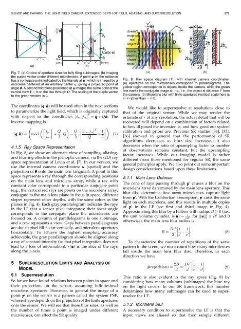
BISHOP AND FAVARO: THE LIGHT FIELD CAMERA: EXTENDED DEPTH OF FIELD, ALIASING, AND SUPERRESOLUTION 977Fig. 7. (a) Choice <strong>of</strong> aperture sizes for fully tiling subimages. (b) Imagingthe purple vector under different microlenses. A point u on the radiancehas a conjugate point indicated by the triangle at u 0 , which is imaged by amicrolens centered at an arbitrary center c, giving a projected point atangle . A second microlens positioned at u images the same point at thecentral view ¼ 0 on the line through O. <strong>The</strong> scaling <strong>of</strong> the purple vectorto the green vectors is .<strong>The</strong> coordinates ðq; kÞ will be used <strong>of</strong>ten in the next sectionsto parameterize the light field, which is originally capturedwith respect to the coordinates ½i m ;j m Š T ¼ q þ Qk. <strong>The</strong>inverse mapping isiðq; kÞ ¼ mod mþ Q $ %!Qj m 2 ;Q 2 ; ½i m ;j m Š Tþ 1 : ð7ÞQ 24.1.5 Ray Space RepresentationIn Fig. 8, we show an alternate view <strong>of</strong> sampling, aliasing,<strong>and</strong> blurring effects in the plenoptic camera, via the (2D) rayspace representation <strong>of</strong> Levin et al. [7]. In our version, weuse the internal camera coordinates: u (spatial) <strong>and</strong> theprojection <strong>of</strong> onto the main lens (angular). A point in thisspace represents a ray through the corresponding positionson the main lens <strong>and</strong> microlens array, while a ray withconstant color corresponds to a particular conjugate point(e.g., the vertical red rays are points on the microlens array,conjugate to the main lens plane in focus in space; differentslopes represent other depths, with the same colors as theplanes in Fig. 4). Each gray parallelogram indicates the raysin the LF that a sensor pixel integrates; their shear anglecorresponds to the conjugate plane the microlenses arefocused on. A column <strong>of</strong> parallelograms is one subimage,<strong>and</strong> a row represents a view. Gaps between parallelogramsare due to pixel fill-factor vertically, <strong>and</strong> microlens apertureshorizontally. To achieve the highest sampling accuracyachievable, the gray parallelogram should be aligned alonga ray <strong>of</strong> constant intensity (so that pixel integration does notlead to a loss <strong>of</strong> information). rðuÞ is the slice <strong>of</strong> the raysalong the x-axis.5 SUPERRESOLUTION LIMITS AND ANALYSIS OFMODEL5.1 SuperresolutionSo far we have found relations between points in space <strong>and</strong>their projections on the sensor, assuming infinitesimalmicrolens apertures. However, in general the image <strong>of</strong> apoint p 0 on the sensor is a pattern called the system PSF,whose shape depends on the projection <strong>of</strong> the finite aperturesonto the sensor. We will see that these blur sizes, as well asthe number <strong>of</strong> times a point is imaged under differentmicrolenses, can affect the SR quality.Fig. 8. Ray space diagram [7], with internal camera coordinates.(a) Apertures on the microlenses correspond to parallelograms. <strong>The</strong>yellow region corresponds to objects inside the camera, while the greenline marks the conjugate image at 1, i.e., the object at distance F fromthe camera. (b) Microlens blur with finite apertures (vertical scale here isvin rather than 0v ).We would like to superresolve at resolutions close tothat <strong>of</strong> the original sensor. While we may render theestimate <strong>of</strong> r at any resolution, the actual detail that will berecovered will depend on a combination <strong>of</strong> factors relatedto how ill posed the inversion is, <strong>and</strong> how good our systemcalibration <strong>and</strong> priors are. Previous SR studies [34], [35],[36] showed in general that the performance <strong>of</strong> SRalgorithms decreases as blur size increases; it alsodecreases when the ratio <strong>of</strong> upsampling factor to number<strong>of</strong> observations remains constant, but the upsamplingfactor increases. While our imaging model is ratherdifferent from those mentioned for regular SR, the samegeneral principles apply. We also point out some importantdesign considerations based upon these limitations.5.1.1 Main Lens Defocus<strong>The</strong> cone <strong>of</strong> rays passing through p 0 causes a blur on themicrolens array determined by the main lens aperture. Thisblur disc determines how many microlenses capture lightfrom p 0 . With the Lambertian assumption, p 0 casts the samelight on each microlens, <strong>and</strong> this results in multiple copies<strong>of</strong> p 0 in the LF (see first <strong>and</strong> third image in Fig. 4).Approximating this blur by a Pillbox with radius B 0 (i.e.,the unit volume cylinder, hðuÞ ¼ 1Bfor kuk 2 2 2 B2 <strong>and</strong> 0otherwise), the main lens blur radius isB ¼ Dv01 12 z 0 v 0 :ð8ÞTo characterize the number <strong>of</strong> repetitions <strong>of</strong> the samepattern in the scene, we must count how many microlensesfall inside the main lens blur disc. <strong>The</strong>refore, in eachdirection we have#repetitions ¼ 2B d ¼ Dv01 1d z 0 v 0 : ð9ÞThis ratio is also evident in the ray space (Fig. 8) byconsidering how many columns (subimages) the blue rayon the right covers. In our SR framework, this numberdetermines how many subimages can be used to superresolvethe LF.5.1.2 Microlens BlurA necessary condition to superresolve the LF is that theinput views are aliased so that they sample different