MIMO Transmission schemes for LTE and HSPA Networks, 3G
MIMO Transmission schemes for LTE and HSPA Networks, 3G
MIMO Transmission schemes for LTE and HSPA Networks, 3G
- No tags were found...
Create successful ePaper yourself
Turn your PDF publications into a flip-book with our unique Google optimized e-Paper software.
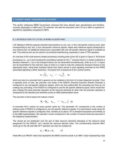
4 CURRENT <strong>MIMO</strong> TRANSMISSION SCHEMESThis section addresses <strong>MIMO</strong> transmission <strong>schemes</strong> that have already been st<strong>and</strong>ardized <strong>and</strong> there<strong>for</strong>ecurrently deployable in <strong>HSPA</strong> <strong>and</strong> <strong>LTE</strong> networks. We start the discussion with <strong>LTE</strong> as it offers a superset ofalgorithmic capabilities compared to <strong>HSPA</strong>.4.1 INTRODUCTION TO <strong>LTE</strong> REL‐8 <strong>MIMO</strong> ALGORITHMS<strong>LTE</strong> Release 8 (Rel-8) supports downlink transmissions on one, two, or four cell-specific antenna ports, eachcorresponding to one, two, or four cell-specific reference signals, where each reference signal corresponds toone antenna port. An additional antenna port, associated with one UE-specific reference signal is available aswell. This antenna port can be used <strong>for</strong> conventional beam<strong>for</strong>ming, especially in case of TDD operation.An overview of the multi-antenna related processing including parts of the UE is given in Figure 9. All bit-levelthprocessing (i.e., up to <strong>and</strong> including the scrambling module) <strong>for</strong> the n transport block in a certain subframe isdenoted codeword n. Up to two transport blocks can be transmitted simultaneously, while up to Q = 4 layerscan be transmitted <strong>for</strong> the rank-four case so there is a need to map the codewords (transport blocks) to theappropriate layer. Using fewer transport blocks than layers serves to save signaling overhead as the HARQassociated signaling is rather expensive. The layers <strong>for</strong>m a sequence of Qx1 symbol vectors:n Tn, 1sn,2 sn,Qs s, (5)which are input to a precoder that in general can be modeled on the <strong>for</strong>m of a linear dispersion encoder. Froma st<strong>and</strong>ard point of view, the precoder only exists if the PDSCH (Physical Downlink Shared CHannel) isconfigured to use cell-specific reference signals, which are then added after the precoding <strong>and</strong> thus do notundergo any precoding. If the PDSCH is configured to use the UE specific reference signal, which would thenalso undergo the same precoder operation as the resource elements <strong>for</strong> data, then the precoder operation istransparent to the st<strong>and</strong>ard <strong>and</strong> there<strong>for</strong>e purely an eNB implementation issue.The precoder is block based <strong>and</strong> outputs a block:X x x x (6)nnLnL1 nLL1of precoded NTx1 vectors <strong>for</strong> every symbol vector sn. The parameter NT corresponds to the number ofantenna ports if PDSCH is configured to use cell specific reference signals. If a transmission mode using UEspecific reference signals is configured, then, similarly as to above, NT is st<strong>and</strong>ard transparent <strong>and</strong> entirely upto the eNB implementation. But typically it would correspond to the number of transmit antennas assumed inthe baseb<strong>and</strong> implementation.The vectors xk are distributed over the grid of data resource elements belonging to the resource blockassignment <strong>for</strong> the PDSCH. Let k denote the resource element index. The corresponding received NRx1vector yk on the UE side after DFT operation can then be modeled as:yk H x e (7)kkkwhere Hk is an NRxNT matrix that represents the <strong>MIMO</strong> channel <strong>and</strong> ek is an NRx1 vector representing noise19


