MIMO Transmission schemes for LTE and HSPA Networks, 3G
MIMO Transmission schemes for LTE and HSPA Networks, 3G
MIMO Transmission schemes for LTE and HSPA Networks, 3G
- No tags were found...

Create successful ePaper yourself
Turn your PDF publications into a flip-book with our unique Google optimized e-Paper software.
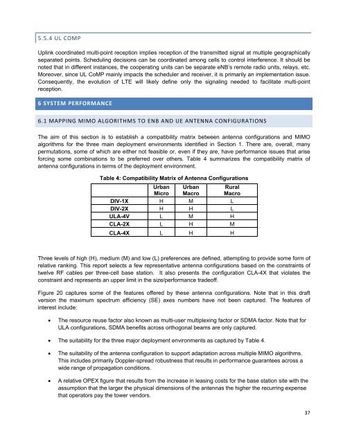
5.5.4 UL COMPUplink coordinated multi-point reception implies reception of the transmitted signal at multiple geographicallyseparated points. Scheduling decisions can be coordinated among cells to control interference. It should benoted that in different instances, the cooperating units can be separate eNB’s remote radio units, relays, etc.Moreover, since UL CoMP mainly impacts the scheduler <strong>and</strong> receiver, it is primarily an implementation issue.Consequently, the evolution of <strong>LTE</strong> will likely define only the signaling needed to facilitate multi-pointreception.6 SYSTEM PERFORMANCE6.1 MAPPING <strong>MIMO</strong> ALGORITHMS TO ENB AND UE ANTENNA CONFIGURATIONSThe aim of this section is to establish a compatibility matrix between antenna configurations <strong>and</strong> <strong>MIMO</strong>algorithms <strong>for</strong> the three main deployment environments identified in Section 1. There are, overall, manypermutations, some of which are either not feasible or, even if they are, have per<strong>for</strong>mance issues that arise<strong>for</strong>cing some combinations to be preferred over others. Table 4 summarizes the compatibility matrix ofantenna configurations in terms of the deployment environment.Table 4: Compatibility Matrix of Antenna ConfigurationsUrbanMicroUrbanMacroRuralMacroDIV-1X H M LDIV-2X H H LULA-4V L M HCLA-2X L H MCLA-4X L H HThree levels of high (H), medium (M) <strong>and</strong> low (L) preferences are defined, attempting to provide some <strong>for</strong>m ofrelative ranking. This report selects a few representative antenna configurations based on the constraints oftwelve RF cables per three-cell base station. It also presents the configuration CLA-4X that violates theconstraint <strong>and</strong> represents an upper limit in the size/per<strong>for</strong>mance tradeoff.Figure 20 captures some of the features offered by these antenna configurations. Note that in this draftversion the maximum spectrum efficiency (SE) axes numbers have not been captured. The features ofinterest include:The resource reuse factor also known as multi-user multiplexing factor or SDMA factor. Note that <strong>for</strong>ULA configurations, SDMA benefits across orthogonal beams are only captured. The suitability <strong>for</strong> the three major deployment environments as captured by Table 4.The suitability of the antenna configuration to support adaptation across multiple <strong>MIMO</strong> algorithms.This includes primarily Doppler-spread robustness that results in per<strong>for</strong>mance guarantees across awide range of propagation conditions.A relative OPEX figure that results from the increase in leasing costs <strong>for</strong> the base station site with theassumption that the larger the physical dimensions of the antennas the higher the recurring expensethat operators pay the tower vendors.37