MIMO Transmission schemes for LTE and HSPA Networks, 3G
MIMO Transmission schemes for LTE and HSPA Networks, 3G
MIMO Transmission schemes for LTE and HSPA Networks, 3G
- No tags were found...

Create successful ePaper yourself
Turn your PDF publications into a flip-book with our unique Google optimized e-Paper software.
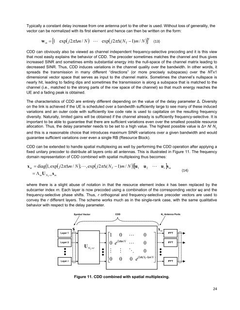
Typically a constant delay increase from one antenna port to the other is used. Without loss of generality, thevector can be normalized with its first element <strong>and</strong> hence can then be written on the <strong>for</strong>m:j2m/ N exp j2(N 1)m w 1 expN (13)mT/CDD can obviously also be viewed as channel independent frequency-selective precoding <strong>and</strong> it is this viewthat most easily explains the behavior of CDD. The precoder sometimes matches the channel <strong>and</strong> thus givesincreased SINR <strong>and</strong> sometimes emits substantial energy into the null-space of the channel matrix leading todecreased SINR. Thus, CDD induces variations in the channel quality over the b<strong>and</strong>width. In other words, itspreads the transmission in many different “directions” (or more precisely subspaces) over the NTx1dimensional vector space that serves as input to the channel matrix. Sometimes the channel’s nullspace isnearly hit, leading to fading dips <strong>and</strong> sometimes the transmission is along a subspace that is matched to thechannel (i.e., matched to the strong parts of the row space of the channel) so that much energy reaches theUE <strong>and</strong> a fading peak is obtained.The characteristics of CDD are entirely different depending on the value of the delay parameter ∆. Diversityon the link is achieved if the UE is scheduled over a b<strong>and</strong>width sufficiently large to see many of these inducedvariations <strong>and</strong> an outer code with sufficiently low code rate is used to capitalize on the resulting frequencydiversity. Naturally, limited gains will be obtained if the channel already is sufficiently frequency-selective. It isimportant to be able to guarantee that there are sufficient variations even over the smallest possible resourceallocation. Thus, the delay parameter needs to be set to a high value. The highest possible value is ∆= N/ N T<strong>and</strong> this is a reasonable choice that introduces maximum SINR variations over a given b<strong>and</strong>width <strong>and</strong> wouldguarantee sufficient variations over even a single RB (Resource Block).CDD can be extended to h<strong>and</strong>le spatial multiplexing as well by per<strong>for</strong>ming the CDD operation after applying afixed unitary precoder to distribute all layers onto all antennas. This is illustrated in Figure 11. The frequencydomain representation of CDD combined with spatial multiplexing thus becomes:xm diag mU1,expj2m/ N ,,expj2(N 1)m / N u u u N rTsmTwhere there is a slight abuse of notation in that the resource element index k has been replaced by thesubcarrier index m. Each layer is now precoded using a combination of the corresponding vector uq <strong>and</strong> thefrequency-selective phase shifts. Thus, r orthogonal <strong>and</strong> frequency-selective precoder vectors are used toconvey the r different layers. The scheme works much as in the single-rank case, with the same qualitativebehavior with respect to the delay parameter.1 T2rsm(14)Symbol VectorCDDN T Antenna PortsLayer 1Layer 2Layer rsUN T r100e0j2m / N00e000j2(N 1)m/NTxmIFFTIFFTIFFTFigure 11. CDD combined with spatial multiplexing.24