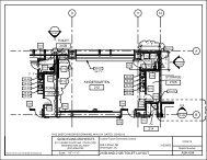
McKINLEY EXTERIOR IMPROVEMENTS_PRODUCT ...
McKINLEY EXTERIOR IMPROVEMENTS_PRODUCT ...
McKINLEY EXTERIOR IMPROVEMENTS_PRODUCT ...
- No tags were found...

You also want an ePaper? Increase the reach of your titles
YUMPU automatically turns print PDFs into web optimized ePapers that Google loves.
RECYCLED CONTENT - LEED ® PROGRAMSHEET MILL GROUP - Crawfordsville, IN; Hickman, AR; Berkeley, SC; Decatur, AL2007 Approximate Recycled Steel Content Of Nucor Sheet Mill Group Products(*)FacilityTotal ScrapSteel UsedTotal Alloys andOther Iron UnitsTotal Post ConsumerRecycled ContentTotal Pre-consumerRecycled ContentCrawfordsville, IN84%16%73%14%Hickman, AR63%37%55%8%Berkley, SC57%43%50%7%Decatur, AL68%32%59%9%The Nucor Sheet Mill Group produces hot band, cold rolled, pickled and galvanized products. Nucor Sheet millsuse varying amounts of recycled materials depending on metallurgical product demands and market conditions.The combined sheet mill total recycled content is approximately 68%.VULCRAFT GROUP -Florence, SC; Norfolk, NE; Brigham City, UT; Grapeland, TX; St. Joe, IN;Fort Payne, AL; Chemung, NYJOISTS - The bar steel for most Vulcraft joists isobtained from one of the ten Nucor bar mills that useover 99% scrap steel as their feedstock. Abreakdown of the recycled content of Nucor bar millproducts is detailed above. Vulcraft facilities mayreceive steel from sources outside of Nucor that maycontain lower amounts of recycled steel. Specificproduct information is available from facilityrepresentatives.DECK – Steel for decking produced by Vulcraft facilitiesare typically obtained from one of the four Nucor sheetmills. A breakdown of the recycled content of Nucorsheet mill products is detailed above. Vulcraft deckproducts contain approximately 68% recycled steel.Additional information is available online through theSteel Recycling Institute at http://www.recycle-steel.org.All figures shown are based on 2007 figures and may vary from year to year. Please contact your localsales representative for current average recycled content for Vulcraft products.(*) Studies show that the recycled steel used for Nucor products consists of approximately 87% post-consumer scrap. The remaining 13%typically consists of pre-consumer scrap generated by manufacturing processes for products made with steel.5
CELLULAR DECKFor: Electrified Raceways — Canopies — Long SpansHeavy Forms — Flat Acoustical CeilingsROOFVulcraft Cellular Units are approved by U.L. for use asElectrical Raceways.1.5BP, 1.5BPA, 3NP, 3NPA FM Global Approved 1Interlocking side lapis not drawn to showactual detail.1.5VLP & 1.5VLPA5.71 In. 2 /Cell1.5BP & 1.5BPA5.71 In. 2 /Cell 3NP & 3NPA2VLP & 2VLPA17.43 In. 2 /Cell12.20 In. 2 /Cell3VLP & 3VLPAACOUSTICAL DATADeck Absorption Coefficients17.82 In. 2 /CellNoise Reduction RALType 125 250 500 1000 2000 4000 Coefficient Test No.1.5BPA 0.34 0.42 0.36 0.22 0.17 0.17 0.30 W/O Insulation A85-1543NPA 0.40 0.38 0.47 0.19 0.11 0.17 0.30 W/O Insulation A85-1561.5VLPA 0.09 0.11 0.25 0.14 0.16 0.28 0.15 W/O Insulation A86-3172VLPA 0.12 0.24 0.20 0.14 0.07 0.18 0.15 W/O Insulation A86-3193VLPA 0.33 0.31 0.30 0.14 0.09 0.01 0.20 W/O Insulation A86-3211.5BPA 0.38 0.49 0.63 0.98 0.74 0.54 0.70 W/ Insulation A85-1553NPA 0.48 0.56 0.98 0.92 0.72 0.58 0.80 W/ Insulation A85-1571.5VLPA 0.14 0.21 0.61 0.99 0.69 0.27 0.65 W/ Insulation A86-3182VLPA 0.31 0.41 0.94 0.88 0.56 0.44 0.70 W/ Insulation A86-3203VLPA 0.40 0.56 1.07 0.78 0.57 0.35 0.75 W/ Insulation A86-322W/Insulation indicates rigid insulation in the cells. Source: Riverbank Acoustical Laboratories.Fy = 33KSISECTION PROPERTIESDeck Hat/Pan Design Thickness W t I S P S NType Gage Hat Pan PSF in 4 /ft in 3 /ft in 3 /ft20/20 .0358 .0358 3.83 .357 .301 .3941.5VLP 20/18 .0358 .0474 4.36 .388 .310 .41318/20 .0474 .0358 4.47 .483 .446 .510and 18/18 .0474 .0474 5.00 .527 .458 .53218/16 .0474 .0598 5.56 .567 .468 .5561.5BP 16/18 .0598 .0474 5.68 .668 .631 .65716/16 .0598 .0598 6.24 .722 .664 .68520/20 .0358 .0358 3.59 .675 .417 .42620/18 .0358 .0474 4.10 .726 .425 .44118/20 .0474 .0358 4.16 .841 .585 .5542VLP 18/18 .0474 .0474 4.67 .902 .595 .57218/16 .0474 .0598 5.22 .960 .606 .58916/18 .0598 .0474 5.28 1.083 .741 .70916/16 .0598 .0598 5.83 1.153 .754 .73120/20 .0358 .0358 3.75 1.484 .650 .65720/18 .0358 .0474 4.26 1.594 .662 .68118/20 .0474 .0358 4.36 1.840 .904 .8533VLP 18/18 .0474 .0474 4.88 1.980 .922 .88318/16 .0474 .0598 5.43 2.103 .936 .91016/18 .0598 .0474 5.54 2.365 1.146 1.09416/16 .0598 .0598 6.09 2.517 1.166 1.12820/20 .0358 .0358 4.30 1.465 .610 .97620/18 .0358 .0474 4.83 1.583 .624 1.01718/20 .0474 .0358 5.08 1.979 .892 1.2663NP 18/18 .0474 .0474 5.61 2.152 .913 1.31518/16 .0474 .0598 6.18 2.308 .933 1.36716/18 .0598 .0474 6.45 2.750 1.257 1.62616/16 .0598 .0598 6.98 2.962 1.285 1.682Notes: 1. FM Global approved numbers and spans available on page 21.12
ANSI/SDI-RD1.0 Standard for Steel Roof Deck1. General1.1 Scope:A. This Specification for Steel RoofDeck shall govern the materials,design, and erection of coldformed steel deck used for thesupport of roofing materials,design live loads and SDIconstruction loads.B. Commentary shall not beconsidered part of themandatory document.1.2 Reference Codes,Standards and Documents:A. Codes and Standards: Forpurposes of this Standard, complywith applicable provisions of thefollowing Codes and Standards:1. American Iron and SteelInstitute (AISI) Standard -North American Specificationfor the Design of Cold-FormedSteel Structural Members,2001 Edition with Supplement20042. American Welding Society -ANSI/AWS D1.3 StructuralWelding Code/Sheet Steel -98 Structural Welding Code -Sheet Steel3. American Society for Testingand Materials (ASTM) A653(A653M)-06, A924 (A924M)-06,A1008 (A1008M)-064. American Society of CivilEngineering (ASCE) –SEI/ASCE7-055. Underwriters Laboratories (UL)Fire Resistance Directory -http://www.ul.com/database2006B. Reference Documents: Refer tothe following documents:1. SDI Manual of Constructionwith Steel Deck - MOC2-20062. SDI Standard Practice Details -SPD2-20013. SDI Position Statement - FieldPainting of Steel Deck-20044. SDI Diaphragm Design Manual -DDM03-20042. Products2.1 Material:A. Sheet steel for galvanized deckshall conform to ASTM A653(A653M) Structural Quality, witha minimum yield strength of33 ksi (230 MPa).B. Sheet steel for cold rolled pluspainted deck shall conform toASTM A1008 (A1008M) with aminimum yield strength of33 ksi (230 MPa). Other structuralsheet steels or high strength lowalloy steels are acceptable,and shall be selected from theNorth American Specificationfor the Design of Cold-Formed SteelStructural Members.C. Sheet steel for accessories shallconform to ASTM A653 (A653M)Structural Quality for structuralaccessories, ASTM A653 (A653M)Commercial Quality fornon-structural accessories, orASTM A1008 (A1008M) for eitherstructural or non-structuralaccessories. Other structuralsheet steels or high strength lowalloy steels are acceptable, andshall be selected from the NorthAmerican Specification for theDesign of Cold-Formed SteelStructural Members.D. The deck type (profile) andthickness (gage) shall be asshown on the plans.2.2 Tolerance:A. Uncoated thickness shall not beless than 95% of the designthickness as listed in Table 2.2.1:B. Panel length shall be within plusor minus 1/2 inch (12 mm) ofspecified length.C. Panel cover width shall be nogreater than minus 3/8 inch(10 mm), plus 3/4 inch (20 mm).D. Panel camber and/or sweep shallbe no greater than 1/4 inch in10 foot length (6 mm in 3 m).E. Panel end out of square shall notbe greater than 1/8 inch per footof panel width (10 mm per m).2.3 Finish:A. Galvanizing shall conform toASTM A653 (A653M).B. Painted with a shop coat ofprimer shall be applied to steelsheet conforming to ASTM A1008(A1008M).C. The finish of the steel roof deckshall be suitable for theenvironment of the structure.ROOF13
ROOFANSI/SDI-RD1.0 Standard for Steel Roof Deck2.3 Finish:Commentary: The primercoat is intended to protect thesteel for only a short period ofexposure in ordinary atmosphericconditions and shall beconsidered an impermanent andprovisional coating. Fieldpainting of prime painted deck isrecommended especiallywhere the deck is exposed. (SeeSDI Field Painting of Steel Deck).In corrosive or high moistureatmospheres, a galvanized finishis desirable in a G60 (Z180) or G90(Z275) coating. In highlycorrosive or chemicalatmospheres or where reactivematerials could be in contactwith the steel deck, special carein specifying the finish shouldbe used.2.4 Design:A. The deck shall be selected bythe designer to provide the loadcapabilities shown on thedrawings (design live and deadloads and the SDI constructionloads).1. The section properties ofthe steel roof unit deck shallbe computed in accordancewith the North AmericanSpecification for the Designof Cold-Formed Steel StructuralMembers.2. Allowable Stress Design (ASD):Bending stress shall notexceed 0.60 times the yieldstrength with a maximum of36 ksi (250 MPa) under thecombined dead and designlive loads.3. Load and Resistance FactorDesign (LRFD): The loadfactors are defined in thegoverning code. ASCE 7 (Seesection 1.2.A.5) shall be usedin the absence of a governingcode. The resistance factorsand nominal resistancesshall be determined inaccordance with the NorthAmerican Specificationfor the Design of Cold-FormedSteel Structural Members.4. Deck Deflection: Deflection ofthe deck shall not exceed1/240 of the span (centerlineto centerline) or 1 inch(25 mm), whichever is less,under the uniformlydistributed design live load. Allspans are to be consideredcenter-to-center of supports.Commentary: The adequacy ofdeck edge support details shouldbe reviewed by the designer. Atthe building perimeter or anyother deck termination ordirection change, occasionalconcentrated loading of theroof deck could result intemporary differences indeflection between the roof deckand the adjacent stationarybuilding component.Supplemental support such as aperimeter angle may bewarranted.5. Suspended Loads: Allsuspended loads shall beincluded in the analysis andcalculations for stress anddeflection.Commentary: The designer musttake into account the sequenceof loading. Suspended loads mayinclude ceilings, light fixtures,ducts or other utilities. Thedesigner must be informed of anyloads applied after the roofinghas been installed.6. Construction and MaintenanceLoads: Deck shall be selectedby the designer to providea minimum 30 lbs/sq.ft.(1.44 kPa) construction load.Span lengths shall begoverned by a maximumstress of 0.7 Fy and amaximum deflection of 1/240of the span with a 200-pound(0.89 kN) concentrated load atmidspan on a 1 foot (300 mm)wide section of deck. If thedesigner contemplates loadsof greater magnitude, spansshall be decreased or thethickness of the steel deckincreased as required. All loadsshall be distributed byappropriate means to preventdamage to the completedassembly during construction.7. Cantilever loads: Thecantilever span shall bedetermined by the lowestvalue considering,(a) construction phase load of10 psf (0.48 kPa) on adjacentspan and cantilever, plus200 pound load (0.89 kN) atend of cantilever with a stresslimit of 0.7 Fy (ASD),(b) a service load of 45 psf(2.15 kPa) on adjacent spanand cantilever, plus 100 poundload (0.44 kN) at end ofcantilever with a stress limit of0.6 Fy (ASD), or(c) with service loads, adeflection limitation of 1/240of adjacent span for interiorspan and deflection limitationat end of cantilever of 1/120of overhang.Commentary: UnderConstruction and MaintenanceLoads, and Cantilever Loads, 0.7 Fymaximum stress was selected tounify the ASD and LRFD values.Apply a load factor of 1.4 to 200pound load when LRFD is used.14
ANSI/SDI-RD1.0 Standard for Steel Roof Deck8. Diaphragm Shear Capacity:Roof deck shear capacityshall be determined inaccordance with the SDIDiaphragm Design Manual orfrom tests conducted by anindependent professionalengineer.Commentary: Calculations ofdiaphragm strength and stiffnessshould be made using the SDIDiaphragm Design Manual. Iftesting is used as the means fordetermining the diaphragmstrength and stiffness, then itshould follow the AISI TS 7-02 testprotocol.B. Load Tables: Uniform loadsdetermined for published tablesshall be based on equal adjacenttwo and three span conditionsand on single spans. Appropriatecombinations of shear andbending shall be made todetermine the published loads.Lengths of 1-1/2 inches (38 mm)for end bearing and 4 inches(100 mm) for interior bearingshall be used to check webcrippling. Deflection coefficientsshall be 0.013 for single spans,0.0054 for double spans and0.0069 for triple spans.Commentary: For deck layoutsthat provide more than threeequal spans, the user can applythe loads published for threespans. Published uniform loadtables do not apply for adjacentspans that differ in length bymore than 10%.2.5 Accessories:A. Ridge and valley plates, and flatplates at change of deck directionshall be furnished as shown onplans to provide a flat (finished)surface for the application of roofinsulation and roof cover.B. Sump pans shall be furnished toreceive roof drains as shown onplans. Holes for drains are to befield cut (by others) in the field.C. Mechanical fasteners or weldsshall be permitted for deck andaccessory attachment.3. Execution3.1 Installation/General:A. Support framing and fieldconditions shall be examined forcompliance with requirementsfor installation tolerances andother conditions affectingperformance of work of thissection. All OSHA rules forerection shall be followed.B. Deck panels and accessoriesshall be installed according tothe SDI Manual of Constructionwith Steel Deck, placement plans,and requirements of this Section.C. Deck panels shall be placed onstructural supports and adjustedto final position with ends aligned,and attached securely to thesupports immediately afterplacement in order to form asafe working platform. All decksheets shall have adequatebearing and fastening to allsupports to prevent slip offduring construction. Deck endsover supports shall be installedwith a minimum end bearingof 1-1/2 inches (38 mm). Deckareas subject to heavy orrepeated traffic, concentratedloads, impact loads, wheel loads,etc. shall be adequately protectedby planking or other approvedmeans to avoid overloading and/ordamage.D. Lapped or Butted Ends: Deckends shall be either lapped orbutted over supports. Gaps upto 1 inch (25 mm) shall bepermitted at butted ends.E. Deck units and accessories shallbe cut and neatly fit aroundscheduled openings and otherwork projecting through oradjacent to the decking.Commentary: It is theresponsibility of the designer todesignate holes/openings to bedecked over in compliance withapplicable federal and stateOSHA directives. Care should betaken to analyze spans betweensupports at openings, whendetermining those holes/openings to be decked over.When a framed opening spanexceeds the maximum deck spanlimits for construction loads, theopening must be detailed aroundinstead of decked over.(Minimum roof constructionload 30 lbs/sq ft (1.44kPa), unlessjob specific requirements dictateotherwise).F. Trades that subsequently cutunscheduled openings throughthe deck shall be responsiblefor reinforcing these openingsbased upon an approvedengineered design.ROOF15
ROOFANSI/SDI-RD1.0 Standard for Steel Roof Deck3.2 Installation/Anchorage:A. Roof deck units shall be anchoredto steel supporting membersincluding perimeter supportsteel and/or bearing walls by arcspot welds of the followingdiameter and spacing, filletwelds of equal strength, ormechanical fasteners. Anchorageshall provide lateral stability tothe top flange of the supportingstructural members and resistthe following minimum grossuplifts; 45 pounds per squarefoot (2.15 kPa) for eave overhang;30 pounds per square foot(1.44 kPa) for all other roof areas.The dead load of the roof deckconstruction shall be deductedfrom the above forces.1. All welding of deck shall bein accordance with ANSI/AWSD1.3, Structural Welding Code -Sheet Steel. Each welder shalldemonstrate an ability toproduce satisfactory weldsusing a procedure such asshown in the SDI Manual ofConstruction with Steel Deck,and/or as described inANSI/AWS D1.3.2. Welding washers shall beused on all deck units withmetal thickness less than0.028 inches (0.7 mm). Weldingwashers shall be a minimumthickness of 0.0598 inches(16 gage, 1.50 mm) and have anominal 3/8 inch (10 mm)diameter hole.3. Where welding washers arenot used, a minimum visible5/8 inch (15 mm) diameterarc puddle weld shall be used.Weld metal shall penetrate alllayers of deck material at endlaps and shall have goodfusion to the supportingmembers.4. Weld spacing: Ribs of panelsshall be welded at eachsupport. Space additionalwelds an average of 12 inches(300 mm) apart but not morethan 18 inches (460 mm).5. When used, fillet welds shallbe at least 1-1/2 inches(38 mm) long.6. Mechanical fasteners, eitherpowder actuated,pneumatically driven, orscrews, shall be permitted inlieu of welding to fastendeck to supporting framingif fasteners meet all projectservice requirements. Whenthe fasteners are powderactuated or pneumaticallydriven, the load value perfastener used to determinethe maximum fastener spacingis based on a minimumstructural support thickness ofnot less than 1/8 inch (3 mm)and on the fastener providinga minimum 5/16 inch (8 mm)diameter bearing surface(fastener head size). When thestructural support thicknessis less than 1/8 inch (3 mm),powder actuated orpneumatically driven fastenersshall not be used, but screwsare acceptable.Commentary: Mechanicalfasteners (screws, powder orpneumatically driven fasteners,etc.) are recognized as viableanchoring methods, providedthe type and spacing of thefastener satisfies the designcriteria. Documentation in theform of test data, designcalculations, or design chartsshould be submitted by thefastener manufacturer as thebasis for obtaining approval.7. For deck units with spansgreater than 5 feet (1.5 m),side laps and perimeter edgesof units between spansupports shall be fastened atintervals not exceeding36 inches (1 m) on center,using one of the followingmethods:a. #10 self drilling screws.b. Crimp or button punch.c. Arc puddle welds 5/8 inch(15 mm) minimum visiblediameter, or minimum1 inch (25 mm) long filletweld.Commentary: The above side lapspacing is a minimum. Serviceloads or diaphragm design mayrequire closer spacing. Goodmetal to metal contact isnecessary for a good side lapweld. Burn holes are to beexpected.B. Accessory Attachment:1. Accessories shall be anchoredto supporting members byarc spot welds or self drillingscrews at 12 inches (300 mm)maximum intervals or asshown on design drawings.16
Steel Roof DeckROOFCANTILEVER DESIGNNotes:1. Adjacent span: Limited to those spans determined in Section 2.4 of Roof DeckStandards. In those instances where the adjacent span is less than 3 times thecantilever span, the individual manufacturer should be consulted for the appropriatecantilever span.2. Sidelaps must be attached at end of cantilever and at a maximum of 12 inches(300 mm) on center from end.3. No permanent suspended loads are to be supported by the steel deck.4. The deck must be completely attached to the supports and at the sidelaps beforeany load is applied to the cantilever.5. Service loads may be more severe than indicated in section 2.4.A.7.17
ROOFShort Form SpecificationsFor Steel Roof Deck1. General1.1 Related DocumentsGeneral provisions of theContract, including General andSupplementary Conditions andGeneral Requirements, apply towork of this section.1.2 SummaryThis section shall include allmaterials, equipment and labornecessary for the installation ofsteel roof deck in accordance withthis specification and designdrawings.Requirements for structural decksupports, field painting,fireproofing, roof sumps,flashings, drains, collars, gutters,downspouts, insulation and othermiscellaneous items are specifiedelsewhere.1.3 SubmittalA. General: Submit each item inthis Article according to theconditions of the Contract andDivision 1 SpecificationSections.B. Product data: Submitmanufacturers’ specifications/installation instructions for eachsteel roof deck type andspecified accessories.C. Shop drawings: Submit roofdeck placement drawingsshowing layout for each typeof deck, anchorage details,sump pans, cut openings andaccessories.D. Welder certification signed bycontractor certifying thatwelders comply with requirementsspecified under “QualityAssurance” Article 1.4. Ifmechanical fastenersare used, independent testreports shall be provided by thefastener manufacturer.1.4 Quality AssuranceA. Codes and Standards - Complywith provisions of the followingunless otherwise indicated:1. American Iron and SteelInstitute (AISI) Specificationfor Design of Cold Formed SteelStructural Members, latestedition.2. American Welding Society(AWS) D1.3 Structural WeldingCode/Sheet Steel.3. Steel Deck Institute (SDI)Design Manual, latest edition.B. Certify that each welder hassatisfactorily passed AWSqualification test for thewelding process involved, and,if applicable, has undergonerecertification.1.5 Delivery, Storage,and HandlingA. Protect steel deck from corrosion,deformation, and other damageduring delivery, storage andhandling.B. If ground storage is needed, thedeck bundles must be storedoff the ground, with one endelevated to provide drainage.Bundles must be protectedagainst condensation with aventilated waterproof covering.Bundles must be stacked sothere is no danger of tipping,sliding, rolling, shifting ormaterial damage. Bundles mustbe periodically checked fortightness, and retightened asnecessary (so wind cannotloosen sheets) to preventdamage caused by the wind.C. Deck bundles placed on thebuilding frame must always beplaced near a main supportingbeam at a column or wall. In nocase are the bundles to beplaced on unbolted frames oron unattached and unbridgedjoists. The structural framemust be properly braced toreceive the bundles.2. Products2.1 A manufacturer offering steelroof deck products to be incorporatedinto the work must be a member of theSteel Deck Institute.2.2 MaterialsA. Steel roof deck shall be (narrowrib) (intermediate rib) (wide rib)(deep rib) (long span)configuration _____ in depthwith a design thicknessof _____ and shall be designedin accordance with and complywith the standard Roof Deckload tables of the SDI.B. Sheet steel for galvanized roofdeck and accessories shallconform to ASTM A653/A653MStructural Quality grade SS33(230 MPa) or higher.1. Galvanizing shall conformto ASTM A924/A924M witha minimum coating class ofG30 (Z090) as defined in ASTMA653/A653M.C. Sheet steel for prime paintedroof deck and/or accessoriesshall conform to ASTM A1008with a minimum yield strengthof 33 ksi (230 MPa).D. Steel deck shall have a coat ofmanufacturers standard shopprimer paint.18
Short Form Specifications2.3 AccessoriesThe deck manufacturer shallfurnish ridge and valley plates, flatplates at change of deck directionand sump pans, as shown on plansto provide a finished surface forthe application of roof insulationand roof covering.3. Execution3.1 Examine support framingand field conditions for compliancewith requirements for installationtolerances and other conditionsaffecting performance of work of thissection. All OSHA, State and Localrules for erection must be followed.3.2 PreparationPlace deck in accordance withapproved placement plans.Locate deck bundles to preventoverloading of support members.3.3 Installation, GeneralA. Install deck panels andaccessories according to SDISpecifications, SDI Manual ofConstruction with Steel Deck,and in accordance with theplacement plans andrequirements of this section.B. Place deck panels on structuralsupports and adjust to finalposition with ends lapped orbutted over structural supportswith a minimum end bearingof 1-1/2 inches (38 mm). Attachthe deck panels firmly to thesupports immediately afterplacement in order to form asafe working platform.C. Cut and neatly fit deck andaccessories at skew conditions,around openings and other workprojecting through or adjacent tothe decking.D. Trades that subsequently cutunscheduled openings throughthe deck are responsible forreinforcing the openings inaccordance with therequirements of the Engineer ofRecord.3.4 AttachmentA. Anchor deck units to steelsupporting members by arc spotpuddle welds or approvedmechanical fasteners.1. Arc spot puddle welds shall be5/8 inch (15 mm) minimumvisible diameter with theattachment pattern shown onplacement drawings.2. Mechanical fasteners, eitherpowder actuated,pneumatically driven, or selfdrilling screws may be used inlieu of welding, providedproduct data has beensubmitted and approved.B. Minimum Side Lap Attachment –Fasten side laps of deck unitswith span greater than 5'-0"(1.5 m) at mid-span or 36" (1 m)intervals whichever distance issmaller or as shown on designdrawings for diaphragm designusing one of the followingmethods:1. #10 self drilling screws.2. Crimp or button punch.3. Arc puddle welds - 5/8 inch(15 mm) minimum visiblediameter, or 1 inch (25 mm)long fillet weld.C. Minimum Edge Attachment –Fasten perimeter edges of deckunits at 36" (1 m) maximumintervals or as shown on designdrawings for diaphragm designusing one of the followingmethods:1. Arc spot puddle welds 5/8 inch(15 mm) minimum visiblediameter or 1 inch (25 mm)long arc seam or fillet weld.2. Mechanical fasteners, eitherpowder actuated,pneumatically driven orscrews may be used in lieu ofwelding, provided product datahas been submitted andapproved.3.5 RepairsBefore placement of roofinsulation and roof covering, thedeck shall be inspected for tears,dents or other damage that mayprevent the deck from acting as astructural roof base. The need forrepair of the damaged deck shallbe determined by the Architect orEngineer of Record.3.6 Construction GuidelinesA. Do not use deck units as aworking platform or storage areauntil units are permanentlyattached in position.B. Construction loads must notexceed load carrying capacityof deck.ROOF19
ROOFROOF DECK FIRE RESISTANCE RATINGSRestrainedAssemblyRating1Hr.1 1/2 Hr.2Hr.3Hr.NOTES:TypeofProtectionExposed GridGypsum BoardCementitiousSprayed FiberUnprotected DeckExposed GridMetal LathGypsum BoardCementitiousSprayed FiberUnprotected DeckExposed GridMetal LathGypsum BoardCementitiousSprayed FiberUnprotected DeckMetal LathTypeofInsulationRigid InsulationInsulating FillRigid InsulationInsulating FillRigid InsulationRigid InsulationInsulating FillRigid InsulationInsulating FillRigid InsulationRigid InsulationRigid InsulationRigid InsulationInsulating FillRigid InsulationInsulating FillRigid InsulationRigid InsulationRigid InsulationRigid InsulationInsulating FillInsulating FillU.L.DesignNo. (1,2)Classified Deck TypeForm DeckP211+ B, BI, F, AP214+ B, BI, F, A 1 Hr.P224+ B, BI, F, AP225+ B, BI, F, A 1,1.5 Hr.P227+ B, BI, F, A 1,1.5 Hr.P230+ B, BI, F, A 1 Hr.P232+ B, BI, F, AP235+ B, BI, F, A 1 Hr.P214+ B, BI, F, A 1 Hr.P231+ 1.0C, 1.0CSV, 1.3C, 1.3CSV, 1.5C 1,1.5 Hr.P246+ 0.6C, 0.6CSV, 1.0C, 1.0CSV, 1.3C, 1.3CSV, 1.5C 1 Hr.P251+ 0.6C, 1.0C, 1.3C, 1.5C 1,1.5,2 Hr.P255+ 0.6C, 0.6CSV, 1.0C, 1.0CSV, 1.3C, 1.3CSV, 1.5C 1 Hr.P510+ B, BI, F, AP509+ 1.3C, 1.3CSV, 1.5C 1 Hr.P701* B, BI, F, A, N, NI 1,1.5,2 Hr.P711* B, BI, F, N, NI 1,1.5,2 Hr.P715* B, BI, F, A, N, NI 1,1.5,2 Hr.P717* B, BI, N, NI 1,1.5,2 Hr.P801* B, BI, F, A, N, NI 1,1.5,2 Hr.P813B,BI,F,A,N,NIP815* B, BI, F, A, N, NI 1,1.5,2 Hr.P816* B, BI, F, N, NI 1,1.5,2 Hr.P817* B, BI, F, N, NI 1,1.5,2 Hr.P818* B, BI, F, N, NI 1,1.5,2 Hr.P819* B, BI, F, N, NI 1,1.5,2 Hr.P902 0.6C, 1.0C, 1.3C, 1.5C B, BI, N, NI 1,1.5,2 Hr.P907 0.6C, 1.0C, 1.3C, 1.5C B, BI, N, NI 1,1.5,2 Hr.P908 0.6C, 1.0C, 1.3C, 1.5C B, BI, N, NI 1,1.5,2 Hr.P919 1.0C, 1.0CSV, 1.3C, 1.3CSV, 1.5C B, BI, N, NI 1,1.5 Hr.P920 1.0C, 1.0CSV, 1.3C, 1.3CSV, 1.5C B, BI, N, NI 1,1.5,2 Hr.P921 0.6C, 0.6CSV, 1.0C, 1.0CSV, 1.3C, 1.3CSV, 1.5C B, BI, N, NI 1,1.5,2 Hr.P922 1.0C, 1.0CSV, 1.3C, 1.3CSV, 1.5C B, BI, N, NI 1,1.5,2 Hr.P923 0.6C, 0.6CSV, 1.0C, 1.0CSV, 1.3C, 1.3CSV, 1.5C B, BI, N, NI 1,1.5,2 Hr.P225+ B, BI, F, A 1,1.5 Hr.P227+ B, BI, F, A 1,1.5 Hr.P230+ B, BI, F, A 1 Hr.P231+ 1.0C, 1.0CSV, 1.3C, 1.3CSV, 1.5C 1,1.5 Hr.P251+ 0.6C, 1.0C, 1.3C, 1.5C 1,1.5,2 Hr.P404+ B, BIP510+ B, BI, F, AP701* B, BI, F, A, N, NI 1,1.5,2 Hr.P711* B, BI, F, N, NI 1,1.5,2 Hr.P715* B, BI, F, A, N, NI 1,1.5,2 Hr.P717* B, BI, N, NI 1,1.5,2 Hr.P801* B, BI, F, A, N, NI 1,1.5,2 Hr.P813B,BI,F,A,N,NIP815* B, BI, F, A, N, NI 1,1.5,2 Hr.P816* B, BI, F, N, NI 1,1.5,2 Hr.P817* B, BI, F, N, NI 1,1.5,2 Hr.P818* B, BI, F, N, NI 1,1.5,2 Hr.P819* B, BI, F, N, NI 1,1.5,2 Hr.P902 0.6C, 1.0C, 1.3C, 1.5C B, BI, N, NI 1,1.5,2 Hr.P907 0.6C, 1.0C, 1.3C, 1.5C B, BI, N, NI 1,1.5,2 Hr.P908 0.6C, 1.0C, 1.3C, 1.5C B, BI, N, NI 1,1.5,2 Hr.P919 1.0C, 1.0CSV, 1.3C, 1.3CSV, 1.5C B, BI, N, NI 1,1.5 Hr.P920 1.0C, 1.0CSV, 1.3C, 1.3CSV, 1.5C B, BI, N, NI 1,1.5,2 Hr.P921 0.6C, 0.6CSV, 1.0C, 1.0CSV, 1.3C, 1.3CSV, 1.5C B, BI, N, NI 1,1.5,2 Hr.P922 1.0C, 1.0CSV, 1.3C, 1.3CSV, 1.5C B, BI, N, NI 1,1.5,2 Hr.P923 0.6C, 0.6CSV, 1.0C, 1.0CSV, 1.3C, 1.3CSV, 1.5C B, BI, N, NI 1,1.5,2 Hr.P237+ B, BI, F, A 2 Hr.P251+ 0.6C, 1.0C, 1.3C, 1.5C 1,1.5,2 Hr.P404+ B, BIP514+ B, BI, F, AP701 B, BI, F, A, N, NI 1,1.5,2 Hr.P711* B, BI, F, N, NI 1,1.5,2 Hr.P715* B, BI, F, A, N, NI 1,1.5,2 Hr.P717* B, BI, N, NI 1,1.5,2 Hr.P801 B, BI, F, A, N, NI 1,1.5,2 Hr.P815* B, BI, F, A, N, NI 1,1.5,2 Hr.P816* B, BI, F, N, NI 1,1.5,2 Hr.P817* B, BI, F, N, NI 1,1.5,2 Hr.P818* B, BI, F, N, NI 1,1.5,2 Hr.P819* B, BI, F, N, NI 1,1.5,2 Hr.P902 0.6C, 1.0C, 1.3C, 1.5C B, BI, N, NI 1,1.5,2 Hr.P907 0.6C, 1.0C, 1.3C, 1.5C B, BI, N, NI 1,1.5,2 Hr.P908 0.6C, 1.0C, 1.3C, 1.5C B, BI, N, NI 1,1.5,2 Hr.P920 1.0C, 1.0CSV,1.3C, 1.3CSV, 1.5C B, BI, N, NI 1,1.5,2 Hr.P921 0.6C, 0.6CSV, 1.0C, 1.0CSV, 1.3C, 1.3CSV, 1.5C B, BI, N, NI 1,1.5,2 Hr.P922 1.0C, 1.0CSV,1.3C, 1.3CSV, 1.5C B, BI, N, NI 1,1.5,2 Hr.P923 0.6C, 0.6CSV, 1.0C, 1.0CSV, 1.3C, 1.3CSV, 1.5C B, BI, N, NI 1,1.5,2 Hr1. Refer to the U.L. "Fire Resistance Directory" for the necessary construction details.2. Deck finish shall be galvanized unless noted otherwise.+ Deck finish is not critical for fire resistance when used in P2--, P4--, & P5-- Series designs.Deck finish shall be galvanized or painted.* Denotes deck finish is critical for fire resistance. Deck finish shall be galvanized or painted.This is a special type of paint and is compatible with the spray-applied fire protection and is U.L.approved for use in the denoted P7-- & P8-- Series designs.Roof DeckUnrestrainedBeamRating20
Vulcraft Steel Deck — FM Global Approved SpansMaximum Vulcraft deck spans approved for use in FM Global constructions are shown below. TheEngineer of Record must investigate the design as published by FM Global for the required attachmentof the steel deck to the supporting structure, deck-to-deck fastening, attachment of insulation to the roofdeck, etc. Reference shall be made to: https://roofnav.fmglobal.comROOF21
ACCESSORIESROOF22
PUBLICATIONSVULCRAFT – (Refer to back cover for address and telephone number of division nearest you)VULCRAFT STEEL JOISTS AND JOIST GIRDERS 2007VULCRAFT COMPOSITE AND NONCOMPOSITE FLOOR JOISTS 1999DESIGNING WITH JOISTS, JOIST GIRDERS AND STEEL DECK, 2 nd EditionJames Fisher, Ph.D., P.E., Michael West, P.E., AIA, Julius P. Van de Pas, P.E.(A 168 page book provided to engineers and architects for help in designingwith steel joists, joist girders and steel deck)STEEL DECK INSTITUTE – P.O. Box 25, Fox River Grove, IL 60021-0025 (847) 458-4647 Fax (847) 458-4648 • www.sdi.orgDesign Manual for Composite Decks, Form Decks & Roof Decks. No. 31DIAPHRAGM DESIGN MANUAL (Third Edition). No. DDMO3MANUAL OF CONSTRUCTION WITH STEEL DECK. No. MOC2COMPOSITE DECK DESIGN HANDBOOK. No. CDD2STANDARD PRACTICE DETAILS. No. SPD2DECK DAMAGE & PENETRATIONS. No. DDPMETAL DECK & CONCRETE QUANTITIES. No. MDCQA RATIONAL APPROACH TO STEEL DECK CORROSION PROTECTION. No. SDCPJOB STORAGE REQUIREMENTS FOR STEEL DECK. No. JSDESIGNING WITH STEEL FORM DECK. No. FORMARC-PUDDLEWELDS AND WELD WASHERS FOR ATTACHMENTS IN STEEL DECK. No. WWSTEEL JOIST INSTITUTE – 3127 Mr. Joe White Avenue, Myrtle Beach, SC 29577-6760(843) 626-1995 Fax (843) 626-5565 www.steeljoist.org42 nd EDITION CATALOG OF STANDARD SPECIFICATIONS AND LOAD TABLES FORSTEEL JOISTS AND JOIST GIRDERS.SEVENTY-FIVE YEAR MANUAL. 1928-2003FIRST EDITION COMPOSIT STEEL JOIST CATALOG. 2007TECHNICAL DIGEST #3 - Ponding (June 2007)TECHNICAL DIGEST #5 - Vibration (March 1988)TECHNICAL DIGEST #6 - Uplift Loading (Revised to July 2003)TECHNICAL DIGEST #8 - Welding of Open Web Steel Joists (August 1983)TECHNICAL DIGEST #9 - Handling and Erection (March 2008)TECHNICAL DIGEST #10 - Fire Resistance (2003)TECHNICAL DIGEST #11 - Lateral Load Resisting Frames (November 2007)TECHNICAL DIGEST #12 - Evaluation and Modification of Steel Joists (2007)COMPUTER VIBRATION PROGRAM Ver. 1.0 (Used in Conjunction With Technical Digest #5)SJI VIDEO - Introduction to Steel JoistsSJI VIDEO - Safe Erection of Open Web Steel Joists and Joist Girders112
Contact the Vulcraft Sales Corporation Office nearest you.Albuquerque, NM AreaPh. (505) 892-0707Fax (505) 892-2727Atlanta, GA AreaPh. (770) 338-9363Fax (770) 338-9757Baltimore, MD AreaPh. (410) 998-0800Fax (410) 998-0801Birmingham, AL AreaPh. (205) 380-0070Fax (205) 380-0077Chicago, IL AreaPh. (630) 887-1400Fax (630) 887-1477Columbia, SC AreaPh. (803) 732-5557Fax (803) 732-5551Dallas, TX AreaPh. (214) 340-1883Fax (214) 340-5897Danbury, CT AreaPh. (203) 791-1227Fax (203) 791-8657Dayton, OH AreaPh. (937) 390-2300Fax (937) 390-2333Denver, CO AreaPh. (303) 757-6323Fax (303) 757-6324Des Moines, IA AreaPh. (515) 270-2500Fax (515) 270-8849Detroit, MI AreaPh. (248) 486-6166Fax (248) 486-6169Fargo, ND AreaPh. (701) 235-6605Fax (701) 234-1966Ft. Wayne/S. Bend, IN AreaPh. (260) 337-1800Fax (260) 337-1801Grand Rapids, MI AreaPh. (616) 949-2106Fax (616) 949-6694Greensboro, NC AreaPh. (336) 294-9544Fax (336) 294-7636Greenville, NC AreaPh. (252) 493-0333Fax (252) 493-0555Houston, TX AreaPh. (281) 477-6700Fax (281) 477-6701Indianapolis, IN AreaPh. (317) 576-5399Fax (317) 576-5395Jackson, MS AreaPh. (601) 936-6215Fax (601) 936-6216Jacksonville, FL AreaPh. (904) 880-1150Fax (904) 880-1151Kansas City AreaPh. (913) 341-9299Fax (913) 341-5764Knoxville, TN AreaPh. (865) 690-6388Fax (865) 690-6389Lexington, KY AreaPh. (859) 271-2591Fax (859) 271-2580Little Rock, AR AreaPh. (501) 758-6454Fax (501) 758-6427Los Angeles, CA AreaPh. (714) 957-5713Fax (714) 957-8871Memphis, TN AreaPh. (901) 751-2154Fax (901) 759-1152Miami, FL AreaPh. (954) 785-8695Fax (954) 785-8696Milwaukee/Green Bay, WI AreaPh. (262) 251-5666Fax (262) 251-7065Minneapolis, MN AreaPh. (763) 425-4399Fax (763) 425-6905Nashville, TN AreaPh. (615) 889-6673Fax (615) 889-0818North Alabama AreaPh. (256) 845-2460Fax (256) 845-2823Oklahoma City, OK AreaPh. (405) 848-2844Fax (405) 842-5855Philadelphia, PA AreaPh. (610) 292-8009Fax (610) 292-8155Phoenix, AZ AreaPh. (480) 730-3012Fax (480) 730-2824Pittsburgh, PA AreaPh. (412) 921-4393Fax (412) 921-4634Richmond, VA AreaPh. (804) 379-3704Fax (804) 379-3709Rochester, NY AreaPh. (585) 288-5595Fax (585) 288-5597Salem, NH AreaPh. (603) 894-1146Fax (603) 894-1149Salt Lake City, UT AreaPh. (801) 355-0431Fax (801) 621-0927San Antonio, TX AreaPh. (210) 655-9070Fax (210) 655-9504San Francisco, CA AreaPh. (925) 229-1020Fax (925) 229-2469Seattle, WA AreaPh. (425) 957-7252Fax (425) 957-7295St. Louis, MO AreaPh. (314) 894-6076Fax (314) 894-9173Tampa, FL AreaPh. (813) 621-0684Fax (813) 626-4955Youngstown, OH AreaPh. (330) 726-8833Fax (330) 726-0694To view a map of the Vulcraft Sales Corporation Office nearest you,logon to our website at www.vulcraft.com
ALABAMA7205 Gault Avenue N.Fort Payne, AL 35967P.O. Box 680169Fort Payne, AL 35968256/845-2460Fax: 256/845-2823INDIANA6610 County Road 60P.O. Box 1000St. Joe, IN 46785260/337-1800Fax: 260/337-1801NEBRASKA1601 West Omaha AvenueNorfolk, NE 68701P.O. Box 59Norfolk, NE 68702402/644-8500Fax: 402/644-8528SOUTH CAROLINA1501 West Darlington StreetP.O. Box 100520Florence, SC 29501843/662-0381Fax: 843/662-3132TEXAS175 County Road 2345P.O. Box 186Grapeland, TX 75844936/687-4665Fax: 936/687-4290UTAH1875 West Highway 13 SouthP.O. Box 637Brigham City, UT 84302435/734-9433Fax: 435/723-5423VULCRAFT OFNEW YORK5362 Railroad StreetP.O. Box 280Chemung, NY 14825607/529-9000Fax: 607/529-9001VULCRAFTNATIONAL ACCOUNTS6230 Shiloh RoadSuite 140Alpharetta, GA 30005678/455-6553Fax: 678/455-9216
®Part #469514Installation InstructionsHoneywell Actuator21-1FIL-1 Drive ArrangementJackshaftInstallation, Operation, and Maintenance InstructionsThis manual is the property of the owner, and is required for future maintenance.Please leave it with the owner when the job is complete.Note: This drawing depicts how the actuator looks after installation. The louver shownis intended to be a general representation and the actual louver model may vary.Reference the drawing on page 2 for an exploded view and parts list.Drive Arrangement 21-1FIL-1JackshaftSAFETY WARNING:Improper installation, adjustment, alteration, service or maintenance can cause property damage, injuryor death. Read the installation, operating, and maintenance instructions thoroughly before installing orservicing this equipment.
Prior to Adjusting1. Louver MUST BE installed level and square for blades tooperate correctly.2. Install actuator and linkage similar to the drawing on page 1and make the following linkage adjustments. Place ball swivelat initial location as show below. Adjust crankarm on theactuator so that it is parallel with linkage rod. If unit is“Fail Open” all adjustments will need to be made withthe actuator in power on positionNote: at this time the blades should fl op freely.3. Loosen nut and bolt on actuator crankarm sothat crank arm rotates freely by hand.Adjustment Process1. With blades closed, rotate crankarm onactuator 1/8 turn toward louver from originalstarting point. Hold blade with ball swivel inclosed position and tighten driver blade ballswivel to drive rod.2. Rotate crankarm on actuator 1/8 turn backto original position. Tighten nut and bolt oncrank arm. This will apply extra pressure toblade seals.Note: For a multiple section unit, adjust actuatorsindependently from each other.Caution: Before operating louver, make surethe ball swivel on the crankarm is in thecorrect location. If the blades are not completely closing the ballswivel can be adjusted SLIGHTLY. An over adjustment can causedamage to the blades.Caution: Before operating the louver, make sure the location of the ballswivel on the crankarm allows the proper travel length.ItemNo.Part No.DA 21-1FIL-0Qty.Description1 416048 1 CS, SCH. SOC. 1/4” x 3/8” ZP & Bake2 822966 1 Anti-Rotation Brkt Assembly3 712711 1 Actuator Mounting Bracket4 415455 1 1/4”-20 Nut Serrated Flange5 451576 3 1/2” x 7/8” Shaft Collar6 415034 1 1/4-20 Serrated Flg Bolt7A 382823Actuator MS4120F1006 120V7B 3828241 RequiredPer UnitActuator MS8120F1002 24V7C 382825 Actuator MS4620F1005 230V8 812097 2 Crankarm Assembly9 150144 1 1/2” Dia Rod (see note)10 451544 4 1/4-20 Ball Swivel11 415934 1 Nut, #10-24 HH Nyloc Zip12 451582 1 1/2” Flgd Brg No. PA-641-413 416010 5 #10-32x1 Threadstud SS14 415991 5 #10-32 SS Kep Nut15 656473 2 5/16 Dia Rod (16” Long)16 814970 1 Jackshaft Bracket AssemblyNote: Jackshaft (10) Length - Unit Section Width + 4”It maybe necessary to adjust the swivel on thecrankarm after the initial adjustments are made.This can be done by sliding the swivel in or outon the crankarm.®Sliding the swivel out on the crankarmwill cause the blade to open more.Sliding the swivel in on the crankarm willcause the blade to close more.Copyright © 2006 Greenheck Fan CorporationHoneywell ActuatorDA 21-1FIL-1, JackshaftDecember 2006Greenheck Fan Corporation reserves the right tomake product changes.
Insulated Control DampersModels ICD• Thermally Insulated • Reduced Condensation• Reduced heat transfer or cold penetration1March2012
Insulated Control Dampers®Greenheck’s ICD series of dampers was developed for applications where it is necessary to minimizethe transfer of heat or cold penetration and reduce condensation. The thermally broken frame providesan insulating barrier in the ductwork. Thermally broken blades separate the warm and cold air inside theductwork. Silicone jamb seals effectively seal the penetration of air from one side of the blade to the other.Design FeaturesVariable Symmetric Blade Design (VSB)Greenheck’s Variable Symmetrical Blade (VSB) designuses a combination of three symmetrical blade sizes (4,5, and 6 inch) to maximize the free area at any damperheight by reducing blade stop height. Traditional damperdesigns use a single blade width that requires oversizedblade stops, limiting free area when the blades areopen. The VSB design allows for consistent operatingcharacteristics regardless of airflow direction.• Increases Mounting Flexibility - Symmetrical bladeshave identical operating characteristics regardlessof airflow direction. This allows a Greenheck controldamper to be mounted in either direction of flow, anadvantage when installing with space constraints.• Increases Free Area - Traditional damper designswith a single blade width require oversized blade stops,limiting free area when the blades are open (Figure 1).Greenheck is able to reduce blade stop height, whichmaximizes free area, and increases damperperformance. AMCA certified pressuredrop lets you know that the published datais accurate to help you better design yoursystem.• Reduces Actuator Torque - If an unsymmetricalblade closes against airflow, a large amount of torqueis needed because the air distribution is unbalanced.Greenheck’s VSB design balances airflow on each sideof a symmetrical blade, reducing the torque required tooperate the damper. The use of symmetrical blades hasallowed Greenheck to reduce the sizes and quantities ofactuators used on our dampers.The ICD series damper blades feature thermally brokenairfoil shaped blade with polyurethane foam.Airflow worksagainstactuatorActuatorTorqueUnbalanced BladeRequires Higher TorqueAirflow worksagainstactuatorAirflowworks withactuatorActuatorTorqueBalanced BladeRequires Less TorqueParallel versus Opposed Blade OperationGreenheck’s ICD series dampers are offered with eitheropposed or parallel blade operation. Parallel bladeorientation is typically used when the damper operatesin two positions, open or closed. The damper bladesopen or close in the same direction. Opposed bladeorientation is typically used on dampers that modulateairflow. Adjacent damper blades will open or closeopposite one another.1/2 in.(13mm)1/2 in.(13mm)1/2 in.(13mm)1/2 in.(13mm)25 in.(127mm)5 in.(127mm)
Insulated Control Dampers®Design FeaturesFrameThere are four frame types available:• Quick Connect for easy connection to duct• Channel• Single Flange• Reversed FlangeThe ICD-44 features an extruded aluminum frame.The ICD-45 features an aluminum frame with twopolyurethane resin gaps and insulated on four sideswith polystyrene.QuickConnectChannelSingleFlangeReverseFlangeLinkageGreenheck’s ICD series dampers have blade linkageconcealed in the insulated frame. This prevents anytransfer point for cold or heat, unlike some of ourcompetitor’s products. The linkage is engineered toaccurately control each and every blade without needfor adjustment.No Top or BottomICD series dampers are designed for installation inany position with the blades horizontal. As shown, thedamper can be turned over so the actuator is on the leftor right side.Blade & Jamb SealsSilicone blade and jamb seals stay flexible in coldtemperatures.The ICD-44 features silicone blade seal with 304SSjamb seals with optional silicone jamb seals. TheICD-45 features silicone blade and jamb seals.BearingsDual bearing with acetal inner sleeve and flanged outerbearing features no metal-to-metal or metal-to-plasticcontact.3
Quick Selection Chart®Maximum Velocity ft/min. (m/s)ICD-444000(20.3)ICD-454000(20.3)Maximum Pressure in. wg (kPa) 8 (2) 8 (2)Temperature range °F (°C)FrameFrame Gauge-70 to 200(-56 to 93)-70 to 200(-56 to 93)Insulated Thermally Broken Aluminum - XAluminum X -.125 in.(3.2mm).125 in.(3.2mm)Channel X OFrame TypeQuick Connect O XReverse Flange O OSingle Flange O OBlade ActionParallel O OOpposed X XBlade Type Insulated Thermally Broken X XBlade Material Extruded Aluminum Airfoil X XBlade Seal Silicone X XJamb Seal304SS X -Silicone O XAxle Bearings Dual Bearing with Acetal Inner Sleeve X XAxle MaterialPlated Steel X X304SS O OLinkagePlated Steel X X304SS O OAnodize O OBaked Enamel O OEpoxy O OPaint Finishes* Hi Pro Polyester O OIndustrial Epoxy O OKynar/Hylar (70%) O OPermatector O OSizingInches (mm)Minimum SizeChannel, Single orReverse FlangeQuick ConnectMaximum Single Section SizeMaximum MultiSection SizeChannel, Single orReverse FlangeQuick Connect* Additional lead time is required. Consult factory.12 x 7(305 x 178)12 x 6(305 x 152)48 x 74(1219 x 1880)144 x 148(3658 x 3759)96 x 148(2438 x 3759)12 x 7(305 x 178)12 x 6(305 x 152)48 x 74(1219 x 1880)144 x 120(3658 x 3048)96 x 120(2438 x 3048)4
Damper PerformanceTesting Criteria®Thermal PerformanceDuring thermal performance test, per ASTM Standard C1363-97conducted at Architectural Testing Laboratories (ATI), the ICD-45outperformed competitor’s thermally broken dampers.(Report #53166.01-201-46)Dry Ice TestThe thermal breaks in the damper blades and frame reduce thetransfer of heat from the “cool side” to the “warm side”. Whencompared to a standard airfoil blade design, ICD airfoil blade,with thermal breaks, prevents ice from forming on the oppositeside of the blade.Specimen Thermal Resistance (R value)GreenheckICD-45Brand ABrand BLeakage TestICD series dampers meet the IECC (International Energy Conservation Code) requirements for damperleakage ratings of at 3 cfm/ft 2 @ 1 in. wg (54.8 cmh/m 2 @ .25 kPa) or less when integral to the buildingenvelope. Leakage testing was performed at Environ Laboratories at a temperature of -40°F. The ICD-45 wasrated at less than 3 cfm/ft 2 @ 1 in. wg (54.8 cmh/m 2 @ .25 kPa) or 8 cfm/ft 2 @ 4 in. wg (146.3 cmh/m 2 @ 1 kPa).Comparing a 36 in. x 36 in. (914mm x 914mm) damper, Greenheck’s ICD series has the lowest leakage in theindustry.GreenheckBrand ABrand B5
Damper PerformanceTesting Criteria®Pressure drop testing was conducted in accordance with AMCA Standard 500-D using the threeconfigurations shown. All data has been corrected to represent standard air at a density of.075 lb/ft 3 (1.201 kg/m 3 ).Actual pressure drop found in any HVAC system is a combination of many factors. This pressure dropinformation along with an analysis of other system influences should be used to estimate actual pressurelosses for a damper installed in a given HVAC system.Figure 5.3 Illustrates a fully ducted damper. This configuration has the lowest pressure drop of the threetest configurations because entrance and exit losses are minimized by straight duct runs upstream anddownstream of the damper.Figure 5.2 Illustrates a ducted damper exhausting air into an open area. This configuration has a lowerpressure drop than Figure 5.5 because entrance losses are minimized by a straight duct run upstream of thedamper.Figure 5.5 Illustrates a plenum mounted damper. This configuration has the highest pressure drop becauseof extremely high entrance and exit losses due to the sudden changes of area in the system.5D6DFigure 5D 5.36D5Dre 5.3Figure 5D 5.2Figure 5.5re 5.2D=4 (W) (H)3.14D=Duct lengthW=Damper widthH=Damper heightFigure 5.54 (W) (H) When comparing a 24 in. x 24 in. (610mm x 610mm)3.14 damper, Greenheck’s ICD series has the lowestpressure drop in the industry which means lower fancost or smaller damper size required.Brand BBrand AGreenheck6
Damper PerformanceTesting Criteria®DimensionInches (mm)Velocity -ft/min. (m/s)AMCA Figure 5.2 Pressure Drop12 x 12(305 x 305)24 x 24(610 x 610)36 x 36(914 x 914)Pressure Drop - in. wg (Pa)12 x 48(305 x 1219)48 x 12(1219 x 305)500 (2.5) .03 (7.5) .02 (5) .01 (2.5) .01 (2.5) .03 (7.5)1000 (5.1) .11 (27.4) .08 (19.9) .05 (12.5) .06 (14.9) .14 (34.8)1500 (7.6) .25 (62.3) .19 (47.3) .11 (27.4) .14 (34.8) .32 (79.7)2000 (10.2) .45 (112) .34 (84.7) .21 (52.3) .25 (62.3) .57 (142)2500 (12.7) .71 (176.9) .53 (132) .33 (82.2) .40 (99.6) .89 (221.7)3000 (15.2) 1.03 (256.6) .77 (191.8) .47 (117.1) .57 (142) 1.29 (321.3)3500 (17.8) 1.40 (348.7) 1.05 (261.5) .64 (159.4) .78 (194.3) 1.76 (438.4)4000 (20.3) 1.83 (455.8) 1.37 (341.3) .84 (209.2) 1.02 (254.1) 2.30 (572.9)Dimension(in.)Velocity -ft/min. (m/s)AMCA Figure 5.3 Pressure Drop12 x 12(305 x 305)24 x 24(610 x 610)36 x 36(914 x 914)Pressure Drop - in. wg (Pa)12 x 48(305 x 1219)48 x 12(1219 x 305)500 (2.5) .01 (2.5) .01 (2.5) .01 (2.5) .01 (2.5) .04 (10)1000 (5.1) .04 (10) .03 (7.5) .02 (5) .02 (5) .06 (14.9)1500 (7.6) .09 (22.4) .08 (19.9) .04 (10) .06 (14.9) .14 (34.8)2000 (10.2) .17 (42.3) .14 (34.8) .08 (19.9) .10 (24.9) .25 (62.3)2500 (12.7) .26 (64.7) .22 (54.8) .12 (29.9) .17 (42.3) .40 (99.6)3000 (15.2) .38 (94.6) .32 (79.7) .18 (44.8) .24 (59.8) .58 (144.5)3500 (17.8) .52 (129.5) .43 (107.1) .24 (59.8) .33 (82.2) .79 (196.7)4000 (20.3) .67 (166.9) .57 (142) .32 (79.7) .43 (107.1) 1.03 (256.6)Dimension(in.)Velocity -ft/min. (m/s)AMCA Figure 5.5 Pressure Drop12 x 12(305 x 305)24 x 24(610 x 610)36 x 36(914 x 914)Pressure Drop - in. wg (Pa)12 x 48(305 x 1219)48 x 12(1219 x 3050500 (2.5) .05 (12.5) .05 (12.5) .03 (7.5) .04 (10) .05 (12.5)1000 (5.1) .23 (57.3) .21 (52.3) .14 (34.8) .18 (44.8) .22 (54.8)1500 (7.6) .52 (129.5) .47 (117.1) .33 (82.2) .42 (104.6) .51 (127)2000 (10.2) .93 (231.7) .84 (209.2) .58 (144.5) .74 (184.3) .90 (224.2)2500 (12.7) 1.44 (358.7) 1.32 (328.8) .91 (226.7) 1.16 (288.9) 1.41 (351.2)3000 (15.2) 2.08 (518.1) 1.9 (473.3) 1.31 (326.3) 1.68 (418.5) 2.04 (508.1)3500 (17.8) 2.83 (704.9) 2.59 (645.1) 1.79 (445.9) 2.28 (567.9) 2.78 (692.5)4000 (20.3) 3.70 (921.6) 3.39 (844.4) 2.34 (582.9) 2.98 (742.3) 3.70 (921.6)Greenheck Fan Corporation certifies that the modelICD-44 and ICD-45 shown herein is licensed tobear the AMCA Seal. The ratings shown are basedon tests and procedures performed in accordancewith AMCA Publication 511 and comply withthe requirements of the AMCA Certified RatingsPrograms. The AMCA Certified Ratings Seal appliesto air performance ratings only.7
The Greenheck DifferenceGreenheck dampers bring the same quality engineering and manufacturing that has earnedGreenheck its position as an industry leader. Aggressive research and development keepsGreenheck a major player in the damper and louver industry.Greenheck has the most UL classified dampers and largestselection of AMCA licensed dampers and louvers in theindustry.In-House TestingState-of-the-art laboratory and testing facilities have alwaysbeen important to Greenheck’s continuing business success.A laboratory facility devoted exclusively to development andtesting of damper and louver related products for testing tothe latest versions of AMCA, ANSI, ASHRAE, UL, Miami-DadeCounty, and other industry standards of performance.Enjoy Greenheck’s extraordinary service, before, duringand after the sale.Greenheck offers added value to our wide selection of top performing, energy-efficient productsby providing several unique Greenheck service programs.• Our Quick Delivery Program ensures shipment of our in-stock products within 24 hours ofplacing your order. Our Quick Build made-to-order products can be produced in 1-3-5-10- or15-day production cycles, depending upon their complexity.• Greenheck’s free Computer Aided Product Selection program (CAPS), rated by many asthe best in the industry, helps you conveniently and efficiently select the right products for thechallenge at hand.• Greenheck has been Green for a long time! Our energy-saving products and ongoingcorporate commitment to sustainability can help you qualify for LEED credits.• Our 3D service allows you to download at no charge lightweight, easy-to-use AutoDesk Revit 3D drawings for many of our ventilation products.Find out more about these special Greenheck services at greenheck.comOur WarrantyGreenheck warrants this equipment to be free from defects in material and workmanship for a periodof one year from the shipment date. Any units or parts which prove defective during the warrantyperiod will be replaced at our option when returned to our factory, transportation prepaid. Motors arewarranted by the motor manufacturer for a period of one year. Should motors furnished by Greenheckprove defective during this period, they should be returned to the nearest authorized motor servicestation. Greenheck will not be responsible for any removal or installation costs.As a result of our commitment to continuous improvement, Greenheck reserves the right to changespecifications without notice.Prepared to SupportGreen Building EffortsP.O. Box 410 • Schofield, WI 54476-0410 • Phone (715) 359-6171 • greenheck.com00.DMP.1005 R2 3-2012 IPCopyright © 2012 Greenheck Fan Corp.
<strong>PRODUCT</strong> DATA SHEETCAFCO ® SprayFilm ® WB 5 INTUMESCENT FIRE PROTECTIONINTERIORIsolatek International’s new CAFCO SprayFilm WB 5 is the generational breakthrough in water-basedintumescent technology which unlocks the door to exposed interior structural steel design once consideredunaffordable.SprayFilm WB 5 requires substantially less material to meet the required fire resistance ratings, makingit the most efficient, cost effective water-based intumescent coating in the industry.<strong>PRODUCT</strong> ADVANTAGES Water-Based intumescent coating withZero VOCs Industry leading Thermal Performance, allowingfor significantly reduced Dry Film Thicknesses(DFTs) compared to the competition Durable, smooth architectural finish Quick, easy application and clean up Can be finished with a wide variety of topcoattypes and colors Contains no solvents or harmful compounds Provides up to 3-hour fire resistance ratings inaccordance with ANSI/UL 263, ASTM E119and CAN/ULC-S101 ICC ES Approved (ICC ESR 1092)APPLICATION A primer must be applied to the steel substrate.Contact Isolatek Technical ServicesDepartment for a complete list of approvedprimers. The applied thickness of CAFCO SprayFilmWB 5 will depend upon the specified fire ratingand size / shape of the steel member to beprotected. If desired, a finish coat may be applied in thedesired color and finish directly over CAFCOSprayFilm WB 5 in accordance with the guidelinesnoted in our Finish Coat Materials datasheet.PHYSICAL PERFORMANCEIt is important for fire protection materials to beable to withstand abuse. American Society forTesting and Materials (ASTM) test methods areused to evaluate the performance of intumescentmaterials when subjected to these various physicalforces. CAFCO SprayFilm WB 5 has beenevaluated to meet rigorous industry test standards.ASTM PHYSICAL CHARACTERISTICSTest Method CAFCO SprayFilm WB 5*SURFACE BURNINGE84Flame Spread - 5Smoke Developed - 30DUROMETER HARDNESS D2240 69 Shore D* Values represent independent laboratory tests under controlled conditions.Class AIMPACT RESISTANCE D2794 152 in-lb (17.17 Nm) @ 2 mmABRASION RESISTANCE D4060 0.2600 g/ 1000 cyclesBOND STRENGTH D4541 340 psi (2013 kPa)PACKAGINGTECHNICAL DATA5 U.S. gallon (19L) pailDENSITY 11.0 lb/gal ±0.5COLORAPPLICATION TEMP.whiteMin. 50ºF (10ºC), Max. 100ºF (38ºC)pH VALUE 8.0 to 8.5VOC COMPLIANCECOVERAGESHELF LIFE0.0 g/L1283 ft 2 /gal @ 1 mil (DFT)12 monthsType SprayFilm-WB 5 OR Type WB 5 File R 16640MASTIC COATINGFIRE RESISTANCE CLASSIFICATIONSEE UL FIRE RESISTANCE DIRECTORYFor more detailed information, visit our website at www.isolatek.comp: 1-800-631-9600 e: technical@isolatek.com or sales@isolatek.com
CAFCO ® SprayFilm ® WB 5 Guide SpecificationSection 07812—Intumescent Fire Resistive MaterialFollowing is an outline/short language specification. Complete specifications for the Spray-Film Systems are available on various media upon request.PART 1 —GENERAL1.1 SCOPE1.1.1 This specification covers labor, materials, equipment, and application necessary for,and incidental to, the complete and proper installation of intumescent fireprotection for application to steel structures and supports in accordance with allapplicable requirements of contract documents.1.1.2 This specification shall be supplemented by the applicable requirements of buildingcodes, insurance rating organizations and all other authorities having jurisdiction.1.2 SECTION INCLUDES1.2.1 Intumescent fire protection material.1.2.2 Topcoat protective decorative finish.1.3 RELATED SECTIONS1.3.1 Section 05100: Structural Steel.1.3.2 Section 05120 - 05500: Structural steel and metal fabrications with reference toprimer receiving fire protection materials.1.3.3 Section 07810: Spray-Applied Fire Resistive Material.1.3.4 Section 07270: Firestopping and Smoke Seals.1.3.5 Section 09900: Painting.1.4 REFERENCES1.4.1 Underwriters Laboratories Inc. (UL) Fire Resistance Directory.1.4.2 Test StandardsA. UL 263 (ASTM E119) - Fire Tests of Building Construction and Materials.B. ASTM E84 (UL723, CAN/ULC-S102) - Surface Burning Characteristics ofBuilding Materials. Class A Rating Required; Flame Spread Maximum: 5 andSmoke Developed Maximum: 30.C. ASTM D2240 – Durometer Hardness (Shore D Only). Minimum: 69 Shore D.D. ASTM D2794 – Impact Resistance. 152 inch-lb (17.17 Nm) @ 2 mm thickness.E. ASTM D4060 – Abrasion Resistance. Maximum 0.2600 grams/1000 cycles.F. ASTM D4541 – Bond Strength. Minimum: 340 psi. (2013 k Pa.)1.4.3 Steel Structures Painting Council (SSPC) Surface Preparation Standards.1.4.4 Material manufacturer's current published information including, but not limited to,application guide.1.4.5 AWCI Technical Manual 12-B "Standard Practice for the Testing and Inspection ofField Applied Thin-Film Intumescent Fire-Resistive Materials; an AnnotatedGuide", Latest Edition.1.5 SYSTEM DESCRIPTION1.5.1 The intumescent fire protection materials shall be applied at the required thicknessto provide the UL fire resistive ratings.1.6 SUBMITTALS1.6.1 Manufacturer's Data: Submit manufacturer's specifications, including certificationas may be required to show material compliance with contract documents.1.7 QUALITY ASSURANCE1.7.1 Manufacturer - Company specializing in manufacturing fire protection products.1.7.2 The intumescent fire resistive material shall be manufactured under the Follow-Up Service program of UL or ULC and bear the UL and/or ULC label (mark).1.7.3 Applicator - A firm with expertise in the installation of fire resistive or similarmaterials. This firm shall be licensed or otherwise approved by fire resistivematerial supplier.1.7.4 Product - The product shall be approved by the architect and applicable authoritieshaving jurisdiction.1.8 DELIVERY, STORAGE AND HANDLING1.8.1 Deliver materials to the project in manufacturer's unopened packages, fullyidentified as to trade name, type and other identifying data. Packaged materialsshall bear the appropriate labels, seals and UL label (mark) for fire resistiveratings and shall be stored at temperatures between 70ºF (21ºC) and 100ºF(38ºC), in a dry interior location away from direct sunlight. DO NOT FREEZE.1.9 PROJECT/SITE CONDITIONS1.9.1 When the temperature at the job site is less than 50ºF (10ºC), a minimumsubstrate and ambient temperature of 50º F (10ºC) shall be maintained prior to,during, and a minimum of 72 hours after application. If necessary for jobschedule, the General Contractor shall provide enclosures and heat tomaintain proper temperatures and humidity levels in the application areas.1.9.2 In enclosed areas, ventilation shall not be less than 4 complete air exchanges perhour until the material is dry.© ISOLATEK International All Rights Reserved1.9.3 Relative humidity shall not exceed 85% throughout the total period of applicationand drying for the intumescent fire resistive material, and must not exceed 85%throughout the application and drying for the protective decorative topcoat.1.10 SEQUENCING AND SCHEDULING1.10.1 Applicator shall cooperate in the coordination and scheduling of fire protection workto avoid delays in job progress.1.10.2 The installation of piping, ducts, conduit or other suspended equipment shall notcommence until the application of the thin-film fire resistive material is completein that area.PART 2—<strong>PRODUCT</strong>S2.1 COMPATIBLE METAL PRIMER2.1.1 Primer shall be approved by manufacturer and applied in full accordance with theprimer manufacturer's written instructions.2.2 INTUMESCENT FIRE PROTECTION SYSTEM2.2.1 The intumescent fire resistive material shall be CAFCO SprayFilm -WB 5 as suppliedby Isolatek International or CAFCO Industries.2.2.2 Intumescent fire resistive material shall be applied in accordance with drawingsand/or specifications, and shall have been tested in accordance with the proceduresof UL 263 or ASTM E119 or CAN/ULC-S101, and reported by UnderwritersLaboratories, Inc. or Underwriters Laboratories of Canada only.2.3 DECORATIVE TOPCOATING2.3.1 Topcoat materials shall be as required for color-coding, aesthetics or additionalsurface protection, and approved by the thin-film fire resistive material manufacturer.PART 3—EXECUTION3.1 PREPARATION3.1.1 All surfaces to receive thin-film fire resistive material shall be clean, dry and freeof oil, grease, loose mill scale, dirt, dust or other materials which would impairbond of the thin-film fire resistive material to the surface. Any cleaning of thesurfaces to receive fire resistive material shall be the responsibility of theGeneral Contractor or steel erector, as outlined in the structural steel section.3.1.2 Confirm compatibility of surfaces to receive thin-film fire resistive material. Steelsurfaces shall be primed with a compatible primer approved by the thin-filmfire resistive material manufacturer.3.1.3 Provide masking, drop cloths or other suitable coverings to prevent overspray ontosurfaces not intended to be coated with intumescent coating.3.2 APPLICATION3.2.1 The thin-film fire resistive material shall be applied at the required dry film thicknessper the appropriate UL design number.3.3 MOCK UP3.3.1 Before proceeding with the work, the applicator shall apply the thin-film fireresistive material to a section witnessed by the architect's or owner's representative.The application shall be subject to their approval and shall be used as aguide for texture and thickness of the finished work.3.4 CLEAN UP AND REPAIR3.4.1 Upon completion of installation, all excess material, overspray and debris shall becleared and removed from the job site.3.4.2 All patching of and repair to thin-film fire resistive material, due to damage byother trades, shall be performed under this section and paid for by the traderesponsible for the damage. Patching shall be performed by applicators licensed orotherwise approved by the manufacturer.3.5 INSPECTION AND TESTING3.5.1 In addition to continuous Wet Film Thickness checks performed by applicator duringapplication, the installed intumescent material shall be inspected by a qualifiedindependent testing laboratory for thickness in accordance with the AWCITechnical Manual 12-B "Standard Practice For The Testing and Inspection Of FieldApplied Thin-Film Intumescent Fire-Resistive Materials; an Annotated Guide",Second Edition, before application of the topcoat.3.5.2 The results of the above tests shall be made available to all parties at thecompletion of each area and approved prior to the application of topcoat.For Further InformationIn the United States: Isolatek International, Stanhope, New Jersey Tel: 800.631.9600 Fax: 973.347.9170In Europe: Isolatek International (Europe) Ltd, UK Tel: +44.1623.726242 Fax: +44.1623.729346In México & Central America: Cafco México S.A. de C.V., México D.F. Tel: 52.55.5254.6683 Fax: 52.55.5531.7826In Canada: Cafco Industries, Toronto (Ontario) Tel: 888.873.0003 Fax: 416.679.2933In Asia: Tel: 60.3.5121.3886 Fax: 60.3.5212.4886For more detailed product information, visit our website at www.isolatek.com or contact us at technical@isolatek.comThe performance data herein reflect our expectations based on tests conducted in accordance with recognized standard methods under controlled conditions. The applicator, generalcontractor, property owner and/or user MUST read, understand and follow the directions, specifications and/or recommendations set forth in Isolatek International's publications concerninguse and application of these products, and should not rely merely on the information contained in this product data sheet. Isolatek International is not responsible for propertydamage, bodily injuries, consequential damages, or losses of any kind that arise from or are related to the applicator's, general contractor's, or property owner's failure to follow therecommendations set forth in Isolatek International's publications. The sale of these products shall be subject to the Terms and Conditions of Sale set forth in the Company's invoices.11/12Total PassiveFire Protection
1CIRCOLO
18 CIRCOLO INVERSE | SATTLER OBJEKTLICHT
Auf modernster LED-Technik basierende Pendelleuchtemit aussenliegendem Acrylglasring,für sehr großflächige, gleichmäßigeAusleuchtungen. Die stabile Bauweise ermöglichteine horizontale und vertikale Montage.CIRCOLO I INVERSEPendant light, based on state-of-the-art LEDtechnology,with exterior acrylic glass framefor homogeneous and large-area illumination.The strong body allows vertical and horizontalinstallation.LED RGB-Farbsteuerung | LED RGB colour controlDESIGN | SATTLER OBJEKTLICHT19
CIRCOLO I INVERSECIRCOLO INVERSE mit LED Spot. 350° drehbar, 50° schwenkbar, 10 W LED.CIRCOLO INVERSE with LED spot. 350 degrees horizontal swivelling, 50 degrees vertical swivelling, 10 W LED.20 CIRCOLO INVERSE | SATTLER OBJEKTLICHT
LED RGB-Farbsteuerung | LED RGB colour controlDESIGN | SATTLER OBJEKTLICHT21
22 CIRCOLO INVERSE | SATTLER OBJEKTLICHT
CIRCOLO I INVERSEIHK Duisburg, Photo: Wibke Evert, Kohl:Fromme ArchitektenDESIGN | SATTLER OBJEKTLICHT23
CIRCOLO IINVERSEØ2300 / 2600Ø1320 / 16001401702260 / 25602-teilig1109 /1351BaldachinCanopy70Gehäuse: Ringförmiges Aluminium-Rahmengehäuse, außenliegender, opaler AcrylglasringMontage: Pendelleuchte, 1-, 3- oder 4-Punkt-Abhängung, Stahlseillänge 5000 mm, mitTechnikeinheit. Horizontale /vertikale Abhängung möglich, (Vertikal auf Anfrage)Eine ausreichende Belastbarkeit der Deckenkonstruktion ist sicherzustellenTechnik: LED-Lichttechnik, kaltweiß 6500 K (wahlweise warmweiß 3700 K)alternativ LED mit variabler Farbtemperatur 2700 - 8000 K, RA >90Optional: LED RGB-Farbsteuerung, Dimmung. LED Spot.Steuerung in Zwischendecke oder in separatem DeckenbaldachinHousing: Circular aluminium profile, opal acrylic glass ring on the outsideInstallation: Pendant light, with 1-, 3- or 4-point steel cable suspension, 5000 mm andpower supply unit. Horizontal and vertical suspension possible, (Vertical on request)Sufficient load capacity of the ceiling structure has to be ensuredSpecifications: LED-technology, cold-white 6500 K (optional warm-white 3700 K)or LED with adjustable colourtemperature 2700 - 8000 K, CRI >90Optional: LED RGB-technology, dimmer. LED spot.Power supply unit in false wall or separate box.Maße L x B x H mm: Watt Gewicht Artikel Nr. weiß anthrazitsize L x W x H mm inch LED weight kg Item No. white anthraciteØ 1320 mm, H 170, B 70 51,9 H 6,7 B 2,7“ 110 20 265.62.01.00 11 30Ø 1600 mm, H 170, B 70 62,9 H 6,7 B 2,7“ 130 25 266.62.01.00 11 30Ø 2300 mm, H 170, B 70 90,5 H 6,7 B 2,7“ 190 35 267.62.01.00 11 30Ø 2600 mm, H 170, B 70 102,3 H 6,7 B 2,7“ 210 40 268.62.01.00 11 30weitere Größen auf Anfrage / further sizes on requestDeckenbaldachin für Technik / Canopy for power supply 6 232.00.00.01 00LED Spot 10W 0,4 252.68.01.10 11Vertikale Abhängung separat bestellen / Please order vertical suspension separatelyDesign:Sattler ObjektlichtIP 20LEDFoptional:RGB24CIRCOLO INVERSE | SATTLER OBJEKTLICHT
1.320 1.600 2.300 2.600DESIGN | SATTLER OBJEKTLICHT25
04.12.1500.DBLIGHT FOR NEW IDEAS...2 012SATTLER GmbHUntere Weingartenstr. 2D -73092 Heiningen - GermanyPhone: +49 (0) 7161 / 920 193 - 0Export: +49 (0) 7161 / 920 193 - 17Fax +49 (0) 7161 / 920 193 - 40eMail: info@sattler-objektlicht.dewww. sattler-objektlicht.de
ISIS®commercial series(3.1 m)27.0"(686 mm)14.5" 12.5"(369 mm) (316 mm)Extension Tubes1 ft (0.3 m) to 15 ft (4.5 m)Standard 1 ft (0.3 m) shownTechnical SpecificationsModel numberNumber and type of airfoilsAirfoil finishWinglet (standard finish)Fan weight (as shown)Prime moverMaximum speedMaximum ampsInput power and required breakerAverage power usage – low/med/high speedController (standard color)Sound level (max speed) 1Minimum airfoil clearances required124.2"(3155 mm)IS1010 patented MiniTEC airfoilsClear anodized aluminumIsis winglet (black)103 lbs (47 kg)Gearless direct drive60 RPM3.9 A100 -125 VAC, 60 Hz, 1 Ol , 10 A15 W / 43 W / 207 WIsis wall switch (white)< 35 dBA10 ft (305 mm) above the floor2 ft (610 mm) on sides2 ft (610 mm) below ceiling deckCertifications ANSI/UL 507CAN/CSA C.22.2 No. 113-08Warranty 210 year warranty with factory installation2425 MERCHANT STREETLEXINGTON, KY 40511SCALE: DESCRIPTION:1:10 10 FT ISIS FAN1Sound level measured at a blade height of 20 ft (6.1 m) and 20 ft (6.1 m) horizontally from center of fan.210 year parts, lifetime airfoils and hub, 1 year labor warranty; certain exclusions may apply. See complete warranty for details.Controller1.76"(44.7 mm)Color Options *Ask about color optionsand other alternative finishesModernWhite4.79"(121.7 mm)1.877.BIGFANSFits standard electrical boxWhite cover plate included3¼" (83 mm) x 5" (130 mm)RavenBlack*Base model is clearanodized aluminumChestnutIsis Sizing ChartCeiling HeightApproximate Room Size 12' (3.7 m) 17' (5.2 m) 22' (6.7 m) 27' (8.2 m)20' x 20' (6.1 m x 6.1 m) 8-ft (2.4 m) 8-ft (2.4 m) 8-ft (2.4 m) 9-ft (2.7 m)30' x 30' (9.1 m x 9.1 m) 8-ft (2.4 m) 9-ft (2.7 m) 9-ft (2.7 m) 10-ft (3.1 m)40' x 40' (12.2 m x 12.2 m) 8-ft (2.4 m) 9-ft (2.7 m) 10-ft (3.1 m) 10-ft (3.1 m)For cooling an active environment such as a gym, use the fan size indicated by the sizing chart set at high speed.For gentle air circulation in an environment such as an office or restaurant, use the fan size indicated by the sizing chart set at a slower speed.Isis Features• Fits flat or sloped ceilings as low as 12 ft (3.7 m)• Silent operation for quiet spaces• Year-round energy savings• Compact and attractive design• Easy to use controllerIsis Options• 8 ft (2.4 m), 9 ft (2.7 m), 10 ft (3.1 m)• Outdoor-use models also available• Automation interface• Color options and custom color matches• 200–250 VAC, 50 Hz, 1 Ol model availableCovered by one or more of the following U.S. Patents: 6,244,821; 6,589,016; 6,817,835; 6,939,108; 7,252,478; 7,284,960; 7,654,798; D587,799; D607,988 and other patents pending.©2011 Delta T Corporation dba the Big Ass Fan Company. All rights reserved. BAF206-08/11-01-00_COM800 Winchester Road | Lexington, KY 40505 | 877-BIG FANS (244-3267)An ISO 9001:2008 certified company
PART 1: GENERAL1.1 WORK INCLUDEDThe ceiling mounted, circulation fan shall be Big Ass Fans. The fan shall be the models scheduled with thecapacities indicated. The fan shall be furnished with mounting hardware and variable speed controls asmanufactured by Big Ass Fan Company.1.2 RELATED WORKFactory installation services are available through Big Ass Fans; consult the appropriate installation scope ofwork for more information. Installation of the fan, miscellaneous or structural metal work (if required), fieldelectrical wiring, cable, conduit, fuses and disconnect switches other than those not addressed in theinstallation scope of work consulted, will be provided by others.PART 2: <strong>PRODUCT</strong>2.1 MANUFACTURERA. Delta T Corporation, dba Big Ass Fans, PO Box 11307, Lexington, Kentucky 40575. Phone (877) 244‐3267.Fax (859) 233‐0139. Website: www.bigassfans.com.2.2 HIGH VOLUME, LOW SPEED FANS – BIG ASS FANS ISIS MODELA. Complete UnitThe fan shall be ETL certified and built pursuant to construction guidelines set forth by UL standards 507and CSA standard 22.2 #0.113. The fan shall be designed to move an effective amount of air for coolingand destratification in small, low ceiling, commercial applications. The fan, in operation, shall not disturbother hanging objects 2’ (61 cm) outside of its circumference to a distance of 3’ (91 cm) below its airfoils.The fan shall incorporate a direct drive system designed specifically for high volume, low speed fans toensure silent operation. The sound levels from the fan operating at maximum speed shall not exceed 40dBA (measured 20’ (6.1 cm) below the blades and 20’ (6.1 cm) horizontally from the center of the fan).B. Airfoils:The fan shall be equipped with ten (10) high volume, low speed airfoils of precision extruded aluminumalloy. Each airfoil shall be of the high performance MiniTEC design. The airfoils shall be connected bymeans of two (2) sets of bolts and lock washers per airfoil. The airfoils shall be connected to the hub andinterlocked with zinc plated steel retainers.C. Winglets:The fan shall be equipped with ten (10) MiniTEC winglets designed to redirect outward airflow intodownward airflow, thereby enhancing the efficiency and effectiveness of the fan. The winglets shall bemolded polyethylene terephthalate thermoplastic polyester resin. A winglet shall be attached at the tip ofeach airfoil. The standard color of the winglets shall be “Super Durable Black.” As an option, winglets maybe powder coated or painted as specified by the architect or owner.D. Motor:The fan motor shall be a permanent magnet brushless motor rated for continuous operation at maximumspeed with the capability of modulating the fan speed from 0‐100% without the use of a gearbox or othermechanical means of control. The motor shall operate from any voltage ranging from 100‐130 VAC, 1 φ,and 60Hz, without requiring adapters or customer selection. The motor shall be a non‐ventilated, heat sinkdesign with the capability of continuous operation in ‐40 o F to 131 o F (‐40 o C to 55 o C) ambient conditions.E. Hub:The fan hub shall be constructed of steel for high strength and durability. The hub shall be precisionmachined to achieve a well balanced and solid rotating assembly. The hub shall incorporate five (5) safetyiBAF 3/10
etaining clips made of 1/8” (0.3 cm) thick steel that shall restrain the hub/airfoil assembly in case of shaftfailure.F. Mounting System:The fan mounting system shall be designed for quick and secure installation from the structure. Allcomponents in the mounting system shall be of welded construction using low carbon steel no less than3/16” (0.5 cm) thick and powder coated or plated for corrosion resistance and appearance. All mountingbolts shall be SAE Grade 8 or equivalent.G. Safety Cable:The fan shall be equipped with a safety cable that provides an additional means of securing the fanassembly to the building structure. The safety cable shall be 3/16” (0.5 cm) diameter and fabricated out of7 x 19 stranded galvanized steel. The loops shall be secured with swaged Nicopress fittings, pre‐loaded andtested to 3,000 lb·f (13,345 N).Field construction of safety cables is not permitted.H. Controller:The fan controller shall be incorporated into the fan assembly. The controller shall be factory programmedto minimize starting and braking torques. The controller shall be equipped with a simple diagnosticprogram and an LED light to identify and relay faults in the system. The controller shall be housed in anenclosure independent of the motor to prevent overheating or electrical interference.I. Wall Control:The fan shall be equipped with a remote wall control. The wall control shall be capable of mounting to astandard electrical box and shall include operator controls and display for controlling the fan’s power andspeed. Communication with the fan drive and controller shall be by a standard (14 Ga/3 wire with ground),line voltage cable that is field installed and provided by the installer.J. Warranty:The manufacturer shall replace any products or components defective in material or workmanship, free ofcharge to the customer (including transportation charges within the USA, F.O.B. Lexington, KY), pursuantto the complete terms and conditions of the Big Ass Fans Commercial, Non‐Prorated Warranty inaccordance to the following schedule:• Airfoils Limited Lifetime (Parts)• Hub Limited Lifetime (Parts)• Motor 10 years (Parts) †• Controller 10 years (Parts) †• Labor 1 year †,†††10 year parts and 1 year labor warranties only valid with factory installation, 5 year parts without factory installation.††All reasonable costs of repair or replacement will be paid or reimbursed provided customer obtains pre‐approval; see fullwarranty for details.Further information on the terms and conditions of the warranties can be found in the Installation Guide.PART 3: ANCILLARY3.1 INSTALLATIONThe fan shall be mounted to an angle iron or I‐beam structure. Consult the Installation Guide for proper sizingand placement of angle iron for a span mount. A structural engineer must be consulted for installationmethods outside the manufacturer’s recommendation and a certification submitted prior to installation.iiBAF 3/10
To reduce the risk of injury to persons, the fan shall be installed so that the airfoils are at least 10’ (3 m) abovethe floor. The fan installation area must be free of obstructions such as lights, cables, sprinklers or otherbuilding structures; with the airfoils at least 2’ (61 cm) clear of all obstructions. The fan should not be installedwhere it will be continuously subjected to wind gusts or in close proximity to the outputs of HVAC systems.If the fan is hung from an extension tube that measures 5’ (1.5 m) or longer, it may be necessary to provideguy cables or struts to limit potential lateral movement of the fan. A stiffening strut braced against anadditional beam may be required if there is a close clearance situation.The design criteria for the fan mounting system shall be capable of handling 40 ft·lbs (54 N·m) of torque.3.2 WORKMANSHIPGood workmanship shall be evident in all aspects of construction. Field balancing of the airfoils shall not benecessary.3.3 DOCUMENTATIONThe manufacturer shall furnish a copy of all operating and maintenance instructions for the fan.All data is subject to change without notice. Data indicated in this document are for your convenience and were correct at the time of printingwith the exception of clerical and/or printing errors. This document supersedes all previously published documents.iiiBAF 3/10