TL494M PULSE-WIDTH-MODULATION CONTROL CIRCUIT
TL494M PULSE-WIDTH-MODULATION CONTROL CIRCUIT
TL494M PULSE-WIDTH-MODULATION CONTROL CIRCUIT
- No tags were found...

Create successful ePaper yourself
Turn your PDF publications into a flip-book with our unique Google optimized e-Paper software.
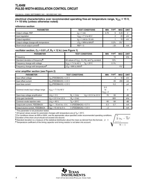
<strong>TL494M</strong><strong>PULSE</strong>-<strong>WIDTH</strong>-<strong>MODULATION</strong> <strong>CONTROL</strong> <strong>CIRCUIT</strong>SGLS041A – D3883, SEPTEMBER 1991 – REVISED MAY 1993electrical characteristics over recommended operating free-air temperature range, V CC = 15 V,f = 10 kHz (unless otherwise noted)reference sectionPARAMETER TEST CONDITIONS MIN TYP† MAX UNITOutput voltage, REF IO = 1 mA 4.75 5 5.25 VInput regulation VCC = 7 V to 40 V 2 25 mVOutput regulation IO = 1 mA to 10 mA 1 15 mVOutput voltage change with temperature ∆TA = MIN to MAX‡ 0.2% 3%*Short-circuit output current§ REF = 0 –25 mAoscillator section, C T = 0.01 µF, R T = 12 kΩ (see Figure 1)PARAMETER TEST CONDITIONS MIN TYP† MAX UNITFrequency 10 kHzStandard deviation of frequency All values of VCC, CT, RT, and TA constant 10%Frequency change with voltage VCC = 7 V to 40 V, TA = 25°C 0.1%Frequency change with temperature# ∆TA = MIN to MAX‡ 1%*error amplifier section (see Figure 2)PARAMETER TEST CONDITIONS MIN TYP† MAX UNITInput offset voltage VO (FEEDBACK) = 2.5 V 2 10 mVInput offset current VO (FEEDBACK) = 2.5 V 25 250 nAInput bias current VO (FEEDBACK) = 2.5 V 0.2 1 µACommon-mode input voltage rangeVCC = 7 V to 40 V0.3toVCC –2Open-loop voltage amplification ∆VO = 3 V, RL = 2 kΩ, VO = 0.5 V to 3.5 V 70 95 dBUnity-gain bandwidth VO = 0.5 V to 3.5 V, RL = 2 kΩ 800 kHzCommon-mode rejection ratio ∆VO = 40 V, TA = 25°C 65 80 dBOutput sink current, FEEDBACK VID = – 15 mV to – 5 V, V (FEEDBACK) = 0.7 V 0.3 0.7 mAOutput source current, FEEDBACK VID = 15 mV to 5 V, V (FEEDBACK) = 3.5 V –2 mA* This parameter is not production tested.† All typical values except for parameter changes with temperature are at TA = 25°C.2‡ For conditions shown as MIN or MAX, use the appropriate value specified under recommended operating conditions. N§ Duration of the short circuit should not exceed one second. (x n X) 2Standard deviation is a measure of the statistical distribution about the mean as derived from the formula:# n 1Temperature coefficient of the timing capacitor and timing resistor is not taken into account.N 1V4POST OFFICE BOX 655303 • DALLAS, TEXAS 75265