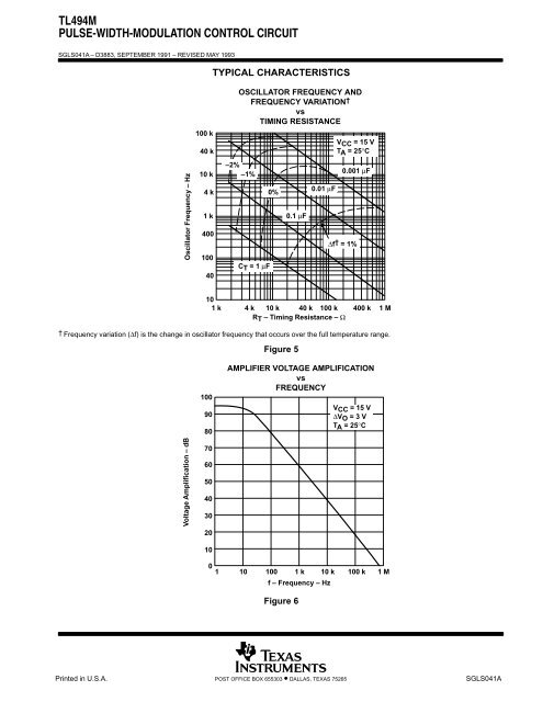
<strong>TL494M</strong><strong>PULSE</strong>-<strong>WIDTH</strong>-<strong>MODULATION</strong> <strong>CONTROL</strong> <strong>CIRCUIT</strong>SGLS041A – D3883, SEPTEMBER 1991 – REVISED MAY 1993TYPICAL CHARACTERISTICSOscillator Frequency – Hz100 k40 k10 k4 k1 k40010040OSCILLATOR FREQUENCY ANDFREQUENCY VARIATION †vsTIMING RESISTANCE–2%–1%CT = 1 µF0%0.1 µF0.01 µFVCC = 15 VTA = 25°C0.001 µF∆f† = 1%101 k 4 k 10 k 40 k 100 k 400 k 1 MRT – Timing Resistance – Ω† Frequency variation (∆f) is the change in oscillator frequency that occurs over the full temperature range.Figure 51009080AMPLIFIER VOLTAGE AMPLIFICATIONvsFREQUENCYVCC = 15 V∆VO = 3 VTA = 25°CVoltage Amplification – dB7060504030201001 10 100 1 k 10 k 100 k 1 Mf – Frequency – HzFigure 6Printed 8 in U.S.A.POST OFFICE BOX 655303 • DALLAS, TEXAS 75265SGLS041A
IMPORTANT NOTICETexas Instruments (TI) reserves the right to make changes to its products or to discontinue any semiconductorproduct or service without notice, and advises its customers to obtain the latest version of relevant informationto verify, before placing orders, that the information being relied on is current.TI warrants performance of its semiconductor products and related software to the specifications applicable atthe time of sale in accordance with TI’s standard warranty. Testing and other quality control techniques areutilized to the extent TI deems necessary to support this warranty. Specific testing of all parameters of eachdevice is not necessarily performed, except those mandated by government requirements.Certain applications using semiconductor products may involve potential risks of death, personal injury, orsevere property or environmental damage (“Critical Applications”).TI SEMICONDUCTOR PRODUCTS ARE NOT DESIGNED, INTENDED, AUTHORIZED, OR WARRANTEDTO BE SUITABLE FOR USE IN LIFE-SUPPORT APPLICATIONS, DEVICES OR SYSTEMS OR OTHERCRITICAL APPLICATIONS.Inclusion of TI products in such applications is understood to be fully at the risk of the customer. Use of TIproducts in such applications requires the written approval of an appropriate TI officer. Questions concerningpotential risk applications should be directed to TI through a local SC sales office.In order to minimize risks associated with the customer’s applications, adequate design and operatingsafeguards should be provided by the customer to minimize inherent or procedural hazards.TI assumes no liability for applications assistance, customer product design, software performance, orinfringement of patents or services described herein. Nor does TI warrant or represent that any license, eitherexpress or implied, is granted under any patent right, copyright, mask work right, or other intellectual propertyright of TI covering or relating to any combination, machine, or process in which such semiconductor productsor services might be or are used.Copyright © 1995, Texas Instruments Incorporated


